

Instruction Manual
Page 1
INSTRUCTIONS Table of electric shock. Do not remove cover (or back). No user serviceable parts inside. DT-V17L3D MULTI FORMAT LCD MONITOR CAUTION RISK OF ELECTRICAL SHOCK DO NOT OPEN CAUTION: To reduce the risk of Contents Safety Precautions 2 IMPORTANT SAFEGUARDS 2 Installation 4 Daily ...-MAIN MENU 10 Menu Configuration-SET-UP MENU 14 External Control 16 About the external control 16 Using the MAKE/TRIGGER system 17 Using the serial communication 18 Troubleshooting 19 Self-check program 20 Maintenance 20 Specifications 21 General 21 Input/output terminals 21 Dimensions...
INSTRUCTIONS Table of electric shock. Do not remove cover (or back). No user serviceable parts inside. DT-V17L3D MULTI FORMAT LCD MONITOR CAUTION RISK OF ELECTRICAL SHOCK DO NOT OPEN CAUTION: To reduce the risk of Contents Safety Precautions 2 IMPORTANT SAFEGUARDS 2 Installation 4 Daily ...-MAIN MENU 10 Menu Configuration-SET-UP MENU 14 External Control 16 About the external control 16 Using the MAKE/TRIGGER system 17 Using the serial communication 18 Troubleshooting 19 Self-check program 20 Maintenance 20 Specifications 21 General 21 Input/output terminals 21 Dimensions...
Instruction Manual
Page 2
... the product for plugging/ unplugging the power cord. on the unit. • AC power: 120 V/220 - 240 V, 50 Hz/60 Hz • DC power: 12 - 17 V 2 • The AC power supply is in fire, electric shock, or other hazards. This product is AC 120 V (For U.S.A. But IMPROPER USE CAN RESULT IN...
... the product for plugging/ unplugging the power cord. on the unit. • AC power: 120 V/220 - 240 V, 50 Hz/60 Hz • DC power: 12 - 17 V 2 • The AC power supply is in fire, electric shock, or other hazards. This product is AC 120 V (For U.S.A. But IMPROPER USE CAN RESULT IN...
Instruction Manual
Page 3
... The inrush current of this apparatus during lightning storms or when unused for example purpose built broadcasting or recording studio), and rural outdoors environment (far away from railways, transmitters, overhead power lines, etc.) ...) If you wish to dispose of this product, please visit our web page www.jvc-europe.com to obtain information about collection point and recycling of this apparatus near the ...prong. Instead, the product should not be disposed as sunshine, fire or the like. 17) When discarding batteries, environmental problems must be used in which case the user will ...
... The inrush current of this apparatus during lightning storms or when unused for example purpose built broadcasting or recording studio), and rural outdoors environment (far away from railways, transmitters, overhead power lines, etc.) ...) If you wish to dispose of this product, please visit our web page www.jvc-europe.com to obtain information about collection point and recycling of this apparatus near the ...prong. Instead, the product should not be disposed as sunshine, fire or the like. 17) When discarding batteries, environmental problems must be used in which case the user will ...
Instruction Manual
Page 8
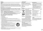
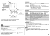
...on page 13) • The EMBEDDED AUDIO signal... - To save ) mode. 8 DVI-D (HDCP) terminal Input terminal for controlling the monitor by using DC 12 V power (maximum DC 17 V), check the DC IN 12V terminal pin signal, and use the correct polarity. Ex.: When the Anton Bauer mount (QR DXC-M3A... or IN 2) terminal. 6 E. If the AC power supply is selected, and when EMBEDDED AUDIO signals come in to this handle when carrying the monitor. Connect the provided AC power cord to an AC outlet. • Attach the provided power cord holder to use the external battery for connections •...
...on page 13) • The EMBEDDED AUDIO signal... - To save ) mode. 8 DVI-D (HDCP) terminal Input terminal for controlling the monitor by using DC 12 V power (maximum DC 17 V), check the DC IN 12V terminal pin signal, and use the correct polarity. Ex.: When the Anton Bauer mount (QR DXC-M3A... or IN 2) terminal. 6 E. If the AC power supply is selected, and when EMBEDDED AUDIO signals come in to this handle when carrying the monitor. Connect the provided AC power cord to an AC outlet. • Attach the provided power cord holder to use the external battery for connections •...
Instruction Manual
Page 9
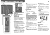
.../24psF Signal format shown in , the signal format is attached to the DVI-D output terminal on the status display. Input signal 17 T.M.D.S Data 0- 18 T.M.D.S Data 0+ 19 T.M.D.S Data 0 shield 20 NC 21 NC 22 T.M.D.S Clock shield 23 T.M.D.S Clock+...; √ √*3 √*3 √ √ DVI-D (HDCP) (Digital component/ digital RGB 3 *1 Analog component signals are available for this monitor. 7 Available signals The following signals are compatible with EMBEDDED AUDIO signals *3 The signal is shown. For other signals, the resolution is recognized as 1080/60i...
.../24psF Signal format shown in , the signal format is attached to the DVI-D output terminal on the status display. Input signal 17 T.M.D.S Data 0- 18 T.M.D.S Data 0+ 19 T.M.D.S Data 0 shield 20 NC 21 NC 22 T.M.D.S Clock shield 23 T.M.D.S Clock+...; √ √*3 √*3 √ √ DVI-D (HDCP) (Digital component/ digital RGB 3 *1 Analog component signals are available for this monitor. 7 Available signals The following signals are compatible with EMBEDDED AUDIO signals *3 The signal is shown. For other signals, the resolution is recognized as 1080/60i...
Instruction Manual
Page 15
... to "OFF" - Displaying the SET-UP MENU (by the MAKE/ TRIGGER system" on !" When you try other operations, " Control lock on page 17 INFORMATION Settings for "PIN6" - Assign the control functions to the pins of these functions.) Setting value RS232C, RS485 MAKE, TRIGGER, SET ☞ "Functions... to assign a video source name for each operation. • The menu automatically disappears in "CHARACTER SET." Display the version of the monitor Item POSITION SOURCE ID CHARACTER SET.*1 STATUS DISPLAY CRC ERROR SUB HOUR METER MODEL VERSION HOUR METER To do Select the input terminal used...
... to "OFF" - Displaying the SET-UP MENU (by the MAKE/ TRIGGER system" on !" When you try other operations, " Control lock on page 17 INFORMATION Settings for "PIN6" - Assign the control functions to the pins of these functions.) Setting value RS232C, RS485 MAKE, TRIGGER, SET ☞ "Functions... to assign a video source name for each operation. • The menu automatically disappears in "CHARACTER SET." Display the version of the monitor Item POSITION SOURCE ID CHARACTER SET.*1 STATUS DISPLAY CRC ERROR SUB HOUR METER MODEL VERSION HOUR METER To do Select the input terminal used...

Instruction Manual
Page 16
...you need it . (2) TRIGGER (trigger) system: Controls the monitor by sending the pulse signal instantaneously to the corresponding pin terminal. ☞ "Using the MAKE/TRIGGER system" on page 17 • RS-485 terminals (RJ-45): Controls the monitor with the RS-485 system. (☞ "Using the serial ...communication" on page 18) • RS-232C terminal (D-sub 9-pin): Controls the monitor with the RS-232C system. (☞ "Using the...
...you need it . (2) TRIGGER (trigger) system: Controls the monitor by sending the pulse signal instantaneously to the corresponding pin terminal. ☞ "Using the MAKE/TRIGGER system" on page 17 • RS-485 terminals (RJ-45): Controls the monitor with the RS-485 system. (☞ "Using the serial ...communication" on page 18) • RS-232C terminal (D-sub 9-pin): Controls the monitor with the RS-232C system. (☞ "Using the...

Instruction Manual
Page 17
...PIN4, PIN5" in "INFORMATION" on the right. When the "TRIGGER" system is selected: Operate each function by pulse control, that the monitor can assign a function to each function by the MAKE system. VIDEO Changes the input to control even when the 7th pin terminal is not ... you want to assign a function, then select the function you can operate only one . "PIN5") for about 1 second and opening it . 17 A.MARKER The area marker indication S.MARKER The safety marker indication FRAME Indication of the area of the specified aspect ratio C.MARKER The center marker indication...
...PIN4, PIN5" in "INFORMATION" on the right. When the "TRIGGER" system is selected: Operate each function by pulse control, that the monitor can assign a function to each function by the MAKE system. VIDEO Changes the input to control even when the 7th pin terminal is not ... you want to assign a function, then select the function you can operate only one . "PIN5") for about 1 second and opening it . 17 A.MARKER The area marker indication S.MARKER The safety marker indication FRAME Indication of the area of the specified aspect ratio C.MARKER The center marker indication...

Instruction Manual
Page 18
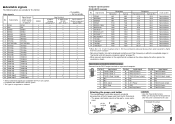
... terminal and the 8th terminal are connected. External Control (cont.) 18 7 Using the serial communication You can be used while the monitor is off the monitor (on standby) 15 ! * **1 B I N A Cr Selects "SDI 1" input 16 ! * **1 B I N B Cr Selects "SDI 2" input 17 ! * **1 B I N C Cr Selects "DVI" input 18 ! * **1 B I N D Cr Selects "COMPO." For details, see on page 7). Header...
... terminal and the 8th terminal are connected. External Control (cont.) 18 7 Using the serial communication You can be used while the monitor is off the monitor (on standby) 15 ! * **1 B I N A Cr Selects "SDI 1" input 16 ! * **1 B I N B Cr Selects "SDI 2" input 17 ! * **1 B I N C Cr Selects "DVI" input 18 ! * **1 B I N D Cr Selects "COMPO." For details, see on page 7). Header...
Instruction Manual
Page 19
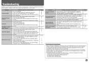
...perform "reset" in the SET-UP MENU. Wrong picture position, wrong picture size. Disable the external control. Page 6, 14 6 9 14 - - 17 15 16,17 The following symptoms are problems only when pictures or sounds are appropriate. • Select the proper color system ("COLOR SYSTEM") in "PICTURE SUB ADJ...8226; Turn on the power of the connected component and set the output correctly. • Check whether the input signal format is acceptable on the monitor. • Adjust the volume level. • Deactivate the muting function. • Connect the signal cable firmly. • Turn on the ...
...perform "reset" in the SET-UP MENU. Wrong picture position, wrong picture size. Disable the external control. Page 6, 14 6 9 14 - - 17 15 16,17 The following symptoms are problems only when pictures or sounds are appropriate. • Select the proper color system ("COLOR SYSTEM") in "PICTURE SUB ADJ...8226; Turn on the power of the connected component and set the output correctly. • Check whether the input signal format is acceptable on the monitor. • Adjust the volume level. • Deactivate the muting function. • Connect the signal cable firmly. • Turn on the ...
Instruction Manual
Page 21
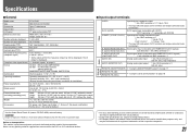
... video signal format Format Audio output Operating conditions Power requirements Rated current External dimensions (excluding protruding parts) Weight Accessories DT-V17L3D Multi format LCD monitor Type 17 wide format 16:10 17˝ wide, active matrix TFT Width: 367.2 mm (14 7/16˝) Height: 229.5 mm (9˝)... Anton Bauer Dionic 90 (mount: QR DXC-M3A) external battery. Never use any packing material supplied from sources other than JVC or JVC-authorized dealers. • For easy understanding, pictures and illustrations are shown by being emphasized, omitted or composed, and may be...
... video signal format Format Audio output Operating conditions Power requirements Rated current External dimensions (excluding protruding parts) Weight Accessories DT-V17L3D Multi format LCD monitor Type 17 wide format 16:10 17˝ wide, active matrix TFT Width: 367.2 mm (14 7/16˝) Height: 229.5 mm (9˝)... Anton Bauer Dionic 90 (mount: QR DXC-M3A) external battery. Never use any packing material supplied from sources other than JVC or JVC-authorized dealers. • For easy understanding, pictures and illustrations are shown by being emphasized, omitted or composed, and may be...