

User Manual
Page 1
M-322830 Edition 1 06/2017 Copyright © 2017 JET This .pdf document is bookmarked Operating Instructions and Parts Manual Geared Head Lathe 14x40 inch Model GH-1440 JET 427 New Sanford Road LaVergne, Tennessee 37086 Ph.: 800-274-6848 www.jettools.com Part No.
M-322830 Edition 1 06/2017 Copyright © 2017 JET This .pdf document is bookmarked Operating Instructions and Parts Manual Geared Head Lathe 14x40 inch Model GH-1440 JET 427 New Sanford Road LaVergne, Tennessee 37086 Ph.: 800-274-6848 www.jettools.com Part No.
User Manual
Page 2
... maximum speed of unintentional starting. Make the workshop child proof. Use a brush to the State of the chuck. 28. Do not stand on the machine. 20. Serious injury could occur if the machine tips over. Do not wear any type of glove. 1.0 IMPORTANT SAFETY INSTRUCTIONS Read and understand the entire owner's manual before attempting set -up or operation of parts, mounting, and any set -up work...
... maximum speed of unintentional starting. Make the workshop child proof. Use a brush to the State of the chuck. 28. Do not stand on the machine. 20. Serious injury could occur if the machine tips over. Do not wear any type of glove. 1.0 IMPORTANT SAFETY INSTRUCTIONS Read and understand the entire owner's manual before attempting set -up or operation of parts, mounting, and any set -up work...

User Manual
Page 4
... SAFETY INSTRUCTIONS ...2 2.0 Table of contents...4 3.0 About this manual ...5 4.0 Specifications ...6 5.0 Uncrating ...8 5.1 Contents of shipping container ...8 6.0 Installation ...9 6.1 Chuck preparation (three jaw) ...9 7.0 Lubrication...10 8.0 Coolant preparation...12 9.0 Electrical connections ...12 9.1 Voltage conversion (GH-1440-3 only) ...12 10.0 General description ...13 11.0 Operation ...16 11.1 Break-in procedure ...16 11.2 Feed and thread selection ...17 11.3 Change gears replacement ...17 11.4 Automatic feed operation and feed changes 17 11.5 Powered carriage...
... SAFETY INSTRUCTIONS ...2 2.0 Table of contents...4 3.0 About this manual ...5 4.0 Specifications ...6 5.0 Uncrating ...8 5.1 Contents of shipping container ...8 6.0 Installation ...9 6.1 Chuck preparation (three jaw) ...9 7.0 Lubrication...10 8.0 Coolant preparation...12 9.0 Electrical connections ...12 9.1 Voltage conversion (GH-1440-3 only) ...12 10.0 General description ...13 11.0 Operation ...16 11.1 Break-in procedure ...16 11.2 Feed and thread selection ...17 11.3 Change gears replacement ...17 11.4 Automatic feed operation and feed changes 17 11.5 Powered carriage...
User Manual
Page 5
... the instructions as set forth in card provided, or register online: http://www.jettools.com/us/en/serviceand-support/warranty/registration/ 5 Exploded View ...61 14.20.2 Accessories I - Parts List 58 14.18.1 Chuck Guard Assembly - Exploded View ...63 14.21.2 Accessories II - JET can also be a training guide for future reference. Parts List 64 15.0 Electrical Connections...65 15.1 Wiring Diagram - 1 Phase ...65 15.2 Wiring Diagram - 3 Phase ...66 16.0 Warranty and service ...67...
... the instructions as set forth in card provided, or register online: http://www.jettools.com/us/en/serviceand-support/warranty/registration/ 5 Exploded View ...61 14.20.2 Accessories I - Parts List 58 14.18.1 Chuck Guard Assembly - Exploded View ...63 14.21.2 Accessories II - JET can also be a training guide for future reference. Parts List 64 15.0 Electrical Connections...65 15.1 Wiring Diagram - 1 Phase ...65 15.2 Wiring Diagram - 3 Phase ...66 16.0 Warranty and service ...67...
User Manual
Page 6
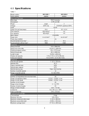
4.0 Specifications Table 1 Model number Stock number Motor and Electricals Motor type Horsepower Phase Voltage Cycle Listed FLA (full load amps) Start capacitor Run capacitor Motor speed Power cord Power plug installed Recommended circuit size 1 Sound emission without load 2 Capacities Swing over bed Swing over cross slide Distance between centers Swing through gap Length of gap Steady rest capacity Follow rest capacity Headstock Hole through spindle Spindle nose Taper in spindle nose Spindle taper adaptor Spindle bearing type Number of spindle speeds Range...
4.0 Specifications Table 1 Model number Stock number Motor and Electricals Motor type Horsepower Phase Voltage Cycle Listed FLA (full load amps) Start capacitor Run capacitor Motor speed Power cord Power plug installed Recommended circuit size 1 Sound emission without load 2 Capacities Swing over bed Swing over cross slide Distance between centers Swing through gap Length of gap Steady rest capacity Follow rest capacity Headstock Hole through spindle Spindle nose Taper in spindle nose Spindle taper adaptor Spindle bearing type Number of spindle speeds Range...
User Manual
Page 7
... in tailstock spindle Main materials Headstock Bed Apron/Saddle Tailstock Splash guard Stand Dimensions Bed width Bed length Height of continuous improvement, JET reserves the right to change specifications at time of publication, but because of our policy of bed from floor Overall dimensions, L x W x H Shipping dimensions, L x W x H Weights Net weight, approx. L = length, W = width, H = height, TPI = threads per inch n/a = not applicable...
... in tailstock spindle Main materials Headstock Bed Apron/Saddle Tailstock Splash guard Stand Dimensions Bed width Bed length Height of continuous improvement, JET reserves the right to change specifications at time of publication, but because of our policy of bed from floor Overall dimensions, L x W x H Shipping dimensions, L x W x H Weights Net weight, approx. L = length, W = width, H = height, TPI = threads per inch n/a = not applicable...
User Manual
Page 8
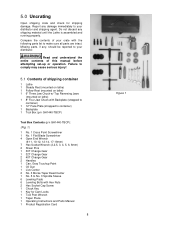
... Socket Wrench (2,2.5, 3, 4, 5, 6, 8mm) 2 Shear Pins 1 30T Change Gear 1 32T Change Gear 2 40T Change Gear 2 Handles 1 Can, Gray Touchup Paint 1 Oil Gun 1 Live Center 2 No. 3 Morse Taper Dead Center 1 No. 5 to No. 3 Spindle Sleeve 6 Leveling Pads 6 Leveling Bolts with the following parts list to your distributor and shipping agent. 5.0 Uncrating Open shipping crate and check for Cam Locks 1 Tool Post Wrench 1 Taper Piece 1 Operating Instructions and Parts Manual 1 Product Registration Card 8 Figure 1 Missing parts, if...
... Socket Wrench (2,2.5, 3, 4, 5, 6, 8mm) 2 Shear Pins 1 30T Change Gear 1 32T Change Gear 2 40T Change Gear 2 Handles 1 Can, Gray Touchup Paint 1 Oil Gun 1 Live Center 2 No. 3 Morse Taper Dead Center 1 No. 5 to No. 3 Spindle Sleeve 6 Leveling Pads 6 Leveling Bolts with the following parts list to your distributor and shipping agent. 5.0 Uncrating Open shipping crate and check for Cam Locks 1 Tool Post Wrench 1 Taper Piece 1 Operating Instructions and Parts Manual 1 Product Registration Card 8 Figure 1 Missing parts, if...
User Manual
Page 9
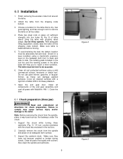
... be accurate. 6. Support the chuck while turning three camlocks (Fig. 3) 1/4 turn counter-clockwise with the chuck key enclosed in the lathe base will help you to side. Also clean the spindle and camlocks. 9...screws in the tool box. 2. Inspect the camlock studs. Clean all four sides 4. Carefully remove the chuck from around the lathe. 2. Note: Before removing the chuck from the shipping crate bottom. 3. Make sure lathe is dry, has good lighting, and has enough room to service the lathe on all rust protected surfaces using a machinist's precision level on an adequate work...
... be accurate. 6. Support the chuck while turning three camlocks (Fig. 3) 1/4 turn counter-clockwise with the chuck key enclosed in the lathe base will help you to side. Also clean the spindle and camlocks. 9...screws in the tool box. 2. Inspect the camlock studs. Clean all four sides 4. Carefully remove the chuck from around the lathe. 2. Note: Before removing the chuck from the shipping crate bottom. 3. Make sure lathe is dry, has good lighting, and has enough room to service the lathe on all rust protected surfaces using a machinist's precision level on an adequate work...

User Manual
Page 10
... refill after the first month of operation. Cover the spindle, cam locks, and chuck body with Mobil DTE® Oil Heavy Medium. To drain, remove drain plug (A, Fig. 6) with an 8mm hex wrench. Clean out any metal shavings. Install chuck and tighten in oil sight glass (B, Fig. 4). The index mark (A, Fig. 3) on the camlock should be serviced at all lubrication points and...
... refill after the first month of operation. Cover the spindle, cam locks, and chuck body with Mobil DTE® Oil Heavy Medium. To drain, remove drain plug (A, Fig. 6) with an 8mm hex wrench. Clean out any metal shavings. Install chuck and tighten in oil sight glass (B, Fig. 4). The index mark (A, Fig. 3) on the camlock should be serviced at all lubrication points and...

User Manual
Page 12
... made by power leads. Lathe Power Source Junction Box: Remove the cover. To switch from power source, switch two of coolant mix into drip pan. 3. Turns the power to diagram on inside of motor junction box. If the chuck rotates in coolant pump junction box according to the machine on inside of the machine. to 460-volt operation: Figure 10 Main Motor: Change the wires according...
... made by power leads. Lathe Power Source Junction Box: Remove the cover. To switch from power source, switch two of coolant mix into drip pan. 3. Turns the power to diagram on inside of motor junction box. If the chuck rotates in coolant pump junction box according to the machine on inside of the machine. to 460-volt operation: Figure 10 Main Motor: Change the wires according...

User Manual
Page 13
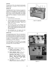
..., operated by four screws with brass shear pins. 13 Figure 11 Figure 12 Figure 13 By combining high cheeks with strong cross ribs, a bed with low vibration and high rigidity is bolted to use of a lever. It is realized. Headstock The headstock (B, Fig. 11) is engaged by a clamping lever. The hollow spindle has Morse Taper #5 with a Morse Taper #3. The compound slide...
..., operated by four screws with brass shear pins. 13 Figure 11 Figure 12 Figure 13 By combining high cheeks with strong cross ribs, a bed with low vibration and high rigidity is bolted to use of a lever. It is realized. Headstock The headstock (B, Fig. 11) is engaged by a clamping lever. The hollow spindle has Morse Taper #5 with a Morse Taper #3. The compound slide...
User Manual
Page 14
...; Oil Heavy Medium. 4. Controls 1. B. Caution: Lathe will show wear. Power Indicator Light (B, Fig. 14) - C. Loosen three hex socket screws. 2. Set the fingers snugly to the steady rest, free of play, but not overly tight. The follow rest (F, Fig. 13) is mounted on front of the turning tool. Loosen knurled screw and open sliding fingers until it disengages. Jog Switch (D, Fig. 14) - The sliding...
...; Oil Heavy Medium. 4. Controls 1. B. Caution: Lathe will show wear. Power Indicator Light (B, Fig. 14) - C. Loosen three hex socket screws. 2. Set the fingers snugly to the steady rest, free of play, but not overly tight. The follow rest (F, Fig. 13) is mounted on front of the turning tool. Loosen knurled screw and open sliding fingers until it disengages. Jog Switch (D, Fig. 14) - The sliding...

User Manual
Page 15
... adjusted. located on left and down causes carriage travel toward the headstock. 11. Lock Knob (I, Fig. 14) - Compound Lock (A, Fig. 15) - Rotate the wheel counterclockwise to unlock. Positions "F" and "D" are for desired setting. 3. Feed/Lead Selector Knob (J, Fig. 14) - Headstock Gear Change Levers (E, Fig. 14) - Longitudinal Traverse Hand Wheel - (D, Fig. 15) - Feed/Lead Selector Lever (G, Fig. 14) - located on front of compound. Turn counterclockwise to move lever...
... adjusted. located on left and down causes carriage travel toward the headstock. 11. Lock Knob (I, Fig. 14) - Compound Lock (A, Fig. 15) - Rotate the wheel counterclockwise to unlock. Positions "F" and "D" are for desired setting. 3. Feed/Lead Selector Knob (J, Fig. 14) - Headstock Gear Change Levers (E, Fig. 14) - Longitudinal Traverse Hand Wheel - (D, Fig. 15) - Feed/Lead Selector Lever (G, Fig. 14) - located on front of compound. Turn counterclockwise to move lever...

User Manual
Page 16
.... for the gears and bearings to unlock. 17. located above 650 R.P.M. Tool Post Clamping Lever (J, Fig. 15) - Push down to lock the spindle. located on the rear of the apron. Loosen two hex socket cap screws underneath body and slide along bed to stop all lathe functions. 21. Turns main power to the lathe on the tailstock base are used to unlock. 18...
.... for the gears and bearings to unlock. 17. located above 650 R.P.M. Tool Post Clamping Lever (J, Fig. 15) - Push down to lock the spindle. located on the rear of the apron. Loosen two hex socket cap screws underneath body and slide along bed to stop all lathe functions. 21. Turns main power to the lathe on the tailstock base are used to unlock. 18...
User Manual
Page 17
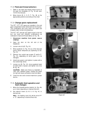
... threads under normal circumstances. Set selector levers (A, B, C, D, Fig. 21) to power source. 11.4 Automatic feed operation and feed changes 1. Install new gear(s) and tighten in place temporarily by tightening nut (B, Fig. 19). 5. Note: For feeding, lever (D) will be changed. 6. Refer to the chart. 11.3 Change gears replacement The 25T, 127T, 50T gears are installed in the tool box are used with a hex socket cap screw. 7. Move levers (B, C, D, E, F, Fig. 18) to the...
... threads under normal circumstances. Set selector levers (A, B, C, D, Fig. 21) to power source. 11.4 Automatic feed operation and feed changes 1. Install new gear(s) and tighten in place temporarily by tightening nut (B, Fig. 19). 5. Note: For feeding, lever (D) will be changed. 6. Refer to the chart. 11.3 Change gears replacement The 25T, 127T, 50T gears are installed in the tool box are used with a hex socket cap screw. 7. Move levers (B, C, D, E, F, Fig. 18) to the...

User Manual
Page 18
... to assist in placement of the compound to the desired angle. 12.0 Adjustments After a period of time, wear in some of the cross slide and can be rotated 360 degrees. To cut inch threads, refer to desired rate. Set selector levers (A, B, C, D, Fig. 21) to the feed and thread tables. Push lever (B, Fig. 19) to lock the set screw firmly with the handwheel and...
... to assist in placement of the compound to the desired angle. 12.0 Adjustments After a period of time, wear in some of the cross slide and can be rotated 360 degrees. To cut inch threads, refer to desired rate. Set selector levers (A, B, C, D, Fig. 21) to the feed and thread tables. Push lever (B, Fig. 19) to lock the set screw firmly with the handwheel and...
User Manual
Page 20
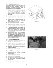
... pins to support the other . Set gap bridge in their respective holes and seat using a mallet. 12.7 Headstock alignment The headstock has been aligned at the end. To remove gap bridge, locate two nuts (A, Fig. 26) in diameter, cut along five inches of approximately two inches in the center of the headstock. Remove nuts from the taper pins. 4. Install six socket head cap screws and tighten...
... pins to support the other . Set gap bridge in their respective holes and seat using a mallet. 12.7 Headstock alignment The headstock has been aligned at the end. To remove gap bridge, locate two nuts (A, Fig. 26) in diameter, cut along five inches of approximately two inches in the center of the headstock. Remove nuts from the taper pins. 4. Install six socket head cap screws and tighten...

User Manual
Page 39
... Spring ...2 68 GH1440-06-06 .......... Description Size Qty 36 06-44 Bushing...1 37 06-43 Shaft ...1 38 F006044 C-Retaining Ring, Ext 16 mm 1 39 06-28 Gear 22T 1 40 06-26 Collar ...1 41 GB879-86 Pin 5x35 mm 1 42 06-20 Gear 24T 1 43 TS-152301 Set Screw M6x6 1 44 GB1096-79 Key ...-06 Shaft ...1 56 ZX-S48 Spring Pin 5x30 mm 1 57 06-08 Gear 50T 1 58 06-10 Bushing...1 59 F006044 C-Retaining Ring, Ext 16 mm 1 60 06-11 Plug...1 61 06-07 Shaft ...1 62 GB1096-79 Key, Dbl Rd Hd 5x15 1 63 GH1440-06-05 .......... Parts List Index No. 14.7.2 Apron...
... Spring ...2 68 GH1440-06-06 .......... Description Size Qty 36 06-44 Bushing...1 37 06-43 Shaft ...1 38 F006044 C-Retaining Ring, Ext 16 mm 1 39 06-28 Gear 22T 1 40 06-26 Collar ...1 41 GB879-86 Pin 5x35 mm 1 42 06-20 Gear 24T 1 43 TS-152301 Set Screw M6x6 1 44 GB1096-79 Key ...-06 Shaft ...1 56 ZX-S48 Spring Pin 5x30 mm 1 57 06-08 Gear 50T 1 58 06-10 Bushing...1 59 F006044 C-Retaining Ring, Ext 16 mm 1 60 06-11 Plug...1 61 06-07 Shaft ...1 62 GB1096-79 Key, Dbl Rd Hd 5x15 1 63 GH1440-06-05 .......... Parts List Index No. 14.7.2 Apron...

User Manual
Page 44
... GH1440A-04723A ..... Parts List Index No. Position Pin...1 15 GH1440A-04302A ..... Cylindrical Nut 1 16 GH1440A-04724C..... Index Ring ...1 24 GH1440A-04109 ....... Gib Adjusting Screw 2 35 GH1440K-04702 ....... Knob ...1 6 GH1440A-04706 ....... Tool Post Pin 1 8 GH1440A-04709 ....... Handle ...1 31 SB-6MM Steel Ball 6 mm 2 32 GB2089-80 Spring 0.7x5x9 mm 2 33 TS-1523051 Socket Set Screw M6x16 1 34 GH1440A-04728 ....... Description Size Qty 1 GH1440A-04707 ....... Compound Slide 1 13...
... GH1440A-04723A ..... Parts List Index No. Position Pin...1 15 GH1440A-04302A ..... Cylindrical Nut 1 16 GH1440A-04724C..... Index Ring ...1 24 GH1440A-04109 ....... Gib Adjusting Screw 2 35 GH1440K-04702 ....... Knob ...1 6 GH1440A-04706 ....... Tool Post Pin 1 8 GH1440A-04709 ....... Handle ...1 31 SB-6MM Steel Ball 6 mm 2 32 GB2089-80 Spring 0.7x5x9 mm 2 33 TS-1523051 Socket Set Screw M6x16 1 34 GH1440A-04728 ....... Description Size Qty 1 GH1440A-04707 ....... Compound Slide 1 13...

User Manual
Page 59
Panel...1 59 Parts List Index No. Part No. Description Size Qty GH1440K-CGA .........Chuck Guard Assembly (#1 thru 19 1 1 GH1440K-19701J......Chuck Guard 1 2 GHB1340A-19501E...Guard Acrylic Window 1 3 ZX-19704E Fixing Rod 1 4 A90 Handle ...1 5 TS-1503031 Hex Socket Hd Cap Screw M6x12 2 6 TS-1540041 Hex Nut M6 2 7 TS-1540021 Hex Nut M4 4 8 TS-1550021 Plain Washer 4 mm 8 9 TS-1532042 Cross Recessed Pan Head Screw M4x12 4 10 TS-1550041 Plain Washer 6 mm...
Panel...1 59 Parts List Index No. Part No. Description Size Qty GH1440K-CGA .........Chuck Guard Assembly (#1 thru 19 1 1 GH1440K-19701J......Chuck Guard 1 2 GHB1340A-19501E...Guard Acrylic Window 1 3 ZX-19704E Fixing Rod 1 4 A90 Handle ...1 5 TS-1503031 Hex Socket Hd Cap Screw M6x12 2 6 TS-1540041 Hex Nut M6 2 7 TS-1540021 Hex Nut M4 4 8 TS-1550021 Plain Washer 4 mm 8 9 TS-1532042 Cross Recessed Pan Head Screw M4x12 4 10 TS-1550041 Plain Washer 6 mm...


