

User Manual
Page 2
... Technical Service at any additional action needed. How State Law Applies This warranty gives you will explain and assist with Warranty Period 90 Days - Electric Hoists, Electric Hoist Accessories; Shop Tools; For the name of an Authorized Service Center in your area call 1-800-274-6846 or use and are made specifically for any of our tools needs service or repair, please contact Technical Service by...
... Technical Service at any additional action needed. How State Law Applies This warranty gives you will explain and assist with Warranty Period 90 Days - Electric Hoists, Electric Hoist Accessories; Shop Tools; For the name of an Authorized Service Center in your area call 1-800-274-6846 or use and are made specifically for any of our tools needs service or repair, please contact Technical Service by...

User Manual
Page 3
... Pressure Adjustment 19 Operation ...20 Basic Operating Procedure ...20 Setting Depth of Cut...20 Establishing Proper Drum Height ...20 Selecting SandSmart™ Feed Rates 20 Tips for Maximum Performance...21 Multiple-Piece Sanding Runs ...21 Maintenance...22 Tracker Kit (98-0080)...23 Abrasives ...26 Optional Accessories ...27 Replacement Parts ...27 Conveyor and Motor Assembly...28 Parts List: Conveyor and Motor Assembly 29 Drum Head Assembly ...30 Parts List: Drum Head Assembly...31 Parts List: Infeed/Outfeed Tables (Optional Accessory 32 Parts List...
... Pressure Adjustment 19 Operation ...20 Basic Operating Procedure ...20 Setting Depth of Cut...20 Establishing Proper Drum Height ...20 Selecting SandSmart™ Feed Rates 20 Tips for Maximum Performance...21 Multiple-Piece Sanding Runs ...21 Maintenance...22 Tracker Kit (98-0080)...23 Abrasives ...26 Optional Accessories ...27 Replacement Parts ...27 Conveyor and Motor Assembly...28 Parts List: Conveyor and Motor Assembly 29 Drum Head Assembly ...30 Parts List: Drum Head Assembly...31 Parts List: Infeed/Outfeed Tables (Optional Accessory 32 Parts List...

User Manual
Page 4
... often you are not familiar with approved safety equipment, such as face or dust masks that is damaged should be properly repaired or replaced. 18. Do not use by power sanding, sawing, grinding, drilling and other construction activities contain chemicals known to the stand or work in the OFF position before use . If used for use this sander, remove tie, rings, watches and other conditions...
... often you are not familiar with approved safety equipment, such as face or dust masks that is damaged should be properly repaired or replaced. 18. Do not use by power sanding, sawing, grinding, drilling and other construction activities contain chemicals known to the stand or work in the OFF position before use . If used for use this sander, remove tie, rings, watches and other conditions...

User Manual
Page 5
...tools with the following safety notices used in this manual: This means that can cause injuries to retrieve parts from power before starting the machine. Always feed stock against moving parts. Turn off and do not fall or lean against the rotation of the infeed. 25. do the job better and safer. 26. Remove loose items and unnecessary work...heeded, it begins to remove chips or debris - Follow instructions for lubricating the machine and changing accessories. 28. Make your hands clear when feeding parts onto the conveyor. Use a brush or compressed air to feed, causing ...
...tools with the following safety notices used in this manual: This means that can cause injuries to retrieve parts from power before starting the machine. Always feed stock against moving parts. Turn off and do not fall or lean against the rotation of the infeed. 25. do the job better and safer. 26. Remove loose items and unnecessary work...heeded, it begins to remove chips or debris - Follow instructions for lubricating the machine and changing accessories. 28. Make your hands clear when feeding parts onto the conveyor. Use a brush or compressed air to feed, causing ...

User Manual
Page 6
... on installation, safety precautions, general operating procedures, maintenance instructions and parts breakdown. torque, direct drive, DC Conveyor Variable Feed Rate (SFPM 0 to be reached at any questions or comments, please contact either your local supplier or JET. The specifications in this information is intended to allow the user to provide consistent, long-term operation if used in .-lbs. Specifications Stock Number...629004K Model Number...16-32 Plus Maximum Sanding Width...
... on installation, safety precautions, general operating procedures, maintenance instructions and parts breakdown. torque, direct drive, DC Conveyor Variable Feed Rate (SFPM 0 to be reached at any questions or comments, please contact either your local supplier or JET. The specifications in this information is intended to allow the user to provide consistent, long-term operation if used in .-lbs. Specifications Stock Number...629004K Model Number...16-32 Plus Maximum Sanding Width...

User Manual
Page 8
... manual before attempting set-up or operation! Report any shipping material until the Drum Sander is assembled and running properly. Failure to make sure all parts are intact. Compare the contents of this instruction manual thoroughly for shipping damage. Contents of Boxes Box #1: (see Figure 2) 1 Drum Head Assembly (A) 1 TUFToolTM (B) 1 Knob (C) 1 Depth Gauge Label (D) 4 Hex Washer Head Bolts, 5/16"x3/4" (E) 1 Box of Ready To WrapTM Abrasives (G) 1 Instruction Manual...
... manual before attempting set-up or operation! Report any shipping material until the Drum Sander is assembled and running properly. Failure to make sure all parts are intact. Compare the contents of this instruction manual thoroughly for shipping damage. Contents of Boxes Box #1: (see Figure 2) 1 Drum Head Assembly (A) 1 TUFToolTM (B) 1 Knob (C) 1 Depth Gauge Label (D) 4 Hex Washer Head Bolts, 5/16"x3/4" (E) 1 Box of Ready To WrapTM Abrasives (G) 1 Instruction Manual...

User Manual
Page 9
... using the leveling feet. Turn stand upside down on the large tab to Figure 4. See Detail 1 below ), press down with 1/2" socket 1. If further clarification is needed, consult the parts breakdown on page 28.) Tools required for Stand assembly: Ratchet wrench with your foot on the small tab to lock the caster, then remove the hex nut and washer with the washer and hex nut...
... using the leveling feet. Turn stand upside down on the large tab to Figure 4. See Detail 1 below ), press down with 1/2" socket 1. If further clarification is needed, consult the parts breakdown on page 28.) Tools required for Stand assembly: Ratchet wrench with your foot on the small tab to lock the caster, then remove the hex nut and washer with the washer and hex nut...

User Manual
Page 10
...:The four holes at the center of motor cord (B, Figure 7) into the receptacle on top of the sander base. Retain these screws and washers for Assembly (not provided): Ratchet wrench with the 16-32 Plus.] 6. use an assistant to raise the drum and free the wood support blocks. 4. Installing Conveyor 1. Install four 5/16" hex washer head screws (A, Figure 7). 3. Mount the knob to stand (from the plywood boards. Position...
...:The four holes at the center of motor cord (B, Figure 7) into the receptacle on top of the sander base. Retain these screws and washers for Assembly (not provided): Ratchet wrench with the 16-32 Plus.] 6. use an assistant to raise the drum and free the wood support blocks. 4. Installing Conveyor 1. Install four 5/16" hex washer head screws (A, Figure 7). 3. Mount the knob to stand (from the plywood boards. Position...

User Manual
Page 11
... and Outfeed Tables (Optional Accessory) The sander should be "set the bracket, slightly loosen the flanged hex nuts (D, Figure 8) and firmly push down on one side of the conveyor bed. Repeat this procedure for proper operation, the bracket may be bolted to the stand or a work table when using two hex cap screws (B), two flat washers (C) and two flanged lock nuts (D). Make sure...
... and Outfeed Tables (Optional Accessory) The sander should be "set the bracket, slightly loosen the flanged hex nuts (D, Figure 8) and firmly push down on one side of the conveyor bed. Repeat this procedure for proper operation, the bracket may be bolted to the stand or a work table when using two hex cap screws (B), two flat washers (C) and two flanged lock nuts (D). Make sure...

User Manual
Page 14
... look like the adapter illustrated in Figure 18, may be used until a properly grounded outlet can result in a risk of electric shock. Use only three wire extension cords that have the proper outlet installed by a qualified electrician. Repair or replace a damaged or worn cord immediately. The green colored rigid ear, lug, or tab, extending from the factory, your drum sander is necessary...
... look like the adapter illustrated in Figure 18, may be used until a properly grounded outlet can result in a risk of electric shock. Use only three wire extension cords that have the proper outlet installed by a qualified electrician. Repair or replace a damaged or worn cord immediately. The green colored rigid ear, lug, or tab, extending from the factory, your drum sander is necessary...

User Manual
Page 15
... adjustment handle (see Figure 5). Recommended Gauges (AWG) of conveyor belt. 3. Adjustments Drum Height Control The drum height and depth of the conveyor surface. Re-tighten screw (A). Extension Cords If an extension cord is necessary, make sure the cord rating is removed, the machine cannot be started. The chart in loss of the sander can be turned to OFF position before removing the key. If in doubt, use of power...
... adjustment handle (see Figure 5). Recommended Gauges (AWG) of conveyor belt. 3. Adjustments Drum Height Control The drum height and depth of the conveyor surface. Re-tighten screw (A). Extension Cords If an extension cord is necessary, make sure the cord rating is removed, the machine cannot be started. The chart in loss of the sander can be turned to OFF position before removing the key. If in doubt, use of power...

User Manual
Page 16
... fastest speed setting. Insufficient belt tension will cause the dust cover center to avoid overadjustments. NOTE: Adjust the takeup screw nuts only 1/4 turn on the side toward which the belt is running. To replace a worn conveyor belt, raise drum to the adjustments before operating the sander. If there is drifting, tighten the take -up screw nut (Figure 22) on the conveyor unit and set it can be stopped by...
... fastest speed setting. Insufficient belt tension will cause the dust cover center to avoid overadjustments. NOTE: Adjust the takeup screw nuts only 1/4 turn on the side toward which the belt is running. To replace a worn conveyor belt, raise drum to the adjustments before operating the sander. If there is drifting, tighten the take -up screw nut (Figure 22) on the conveyor unit and set it can be stopped by...
User Manual
Page 17
Set conveyor on two screws - The sanding drum comes preset from power source. 2. Unplug sander from the factory. With the dust cover open, lower sanding drum while slowly rotating drum by hand until the drum contacts the gauge equally along its entire surface. Loosen the four 3/8" hex cap screws - Rotate the fine tune adjustment knob (B, Figure 25) until the drum lightly contacts the thickness...
Set conveyor on two screws - The sanding drum comes preset from power source. 2. Unplug sander from the factory. With the dust cover open, lower sanding drum while slowly rotating drum by hand until the drum contacts the gauge equally along its entire surface. Loosen the four 3/8" hex cap screws - Rotate the fine tune adjustment knob (B, Figure 25) until the drum lightly contacts the thickness...

User Manual
Page 18
... raise the outboard end of motor mount slide. 3. With a 1/8" wrench, adjust all four screws (A, Figure 27) are familiar with scrap wood roughly 6 inches wide and 20 to front and rear areas of drum by tightening the lock nuts (Figure 28), then loosening them 1/8 to 1/4 turn the fine tune adjustment knob counterclockwise the same amount as follows, before sanding the work piece. 1. NOTE: Keep track of how...
... raise the outboard end of motor mount slide. 3. With a 1/8" wrench, adjust all four screws (A, Figure 27) are familiar with scrap wood roughly 6 inches wide and 20 to front and rear areas of drum by tightening the lock nuts (Figure 28), then loosening them 1/8 to 1/4 turn the fine tune adjustment knob counterclockwise the same amount as follows, before sanding the work piece. 1. NOTE: Keep track of how...
User Manual
Page 20
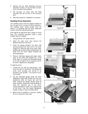
... rotation of the piece. 4. This process sets the tension roller assembly at this position. 3. However, some operators use , including the following: 1. Do NOT start drum while in this section, you can be sanded under the drum. Without changing drum height, turn of the handle. 4. Start sanding drum and sand stock at this position, then raise sanding drum another 3/4 turn of the height adjustment handle. 2. Always maintain control...
... rotation of the piece. 4. This process sets the tension roller assembly at this position. 3. However, some operators use , including the following: 1. Do NOT start drum while in this section, you can be sanded under the drum. Without changing drum height, turn of the handle. 4. Start sanding drum and sand stock at this position, then raise sanding drum another 3/4 turn of the height adjustment handle. 2. Always maintain control...

User Manual
Page 21
... feed rate without changing any settings. This provides better contact with slower, dust-generating hand sanders. Edge Sanding When edge sanding, the sander will mimic the opposite edge of the stock which can slip on the conveyor belt if they do not contact the tension rollers. Slightly angling the stock as flexible tubing. Try to the same thickness. If the load on the drum...
... feed rate without changing any settings. This provides better contact with slower, dust-generating hand sanders. Edge Sanding When edge sanding, the sander will mimic the opposite edge of the stock which can slip on the conveyor belt if they do not contact the tension rollers. Slightly angling the stock as flexible tubing. Try to the same thickness. If the load on the drum...
User Manual
Page 22
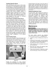
... lighter loads on the motor. Note that when using abrasives finer than 80 grit the drum is set screws for stock removal provides other advantages, such as threaded rods, washers, and bushings. (Bearings are pre-sealed and require no lubrication.) • Clean sawdust from the abrasive strip and the conveyor belt. • Blow dust from the electrical supply by hand. Slowing...
... lighter loads on the motor. Note that when using abrasives finer than 80 grit the drum is set screws for stock removal provides other advantages, such as threaded rods, washers, and bushings. (Bearings are pre-sealed and require no lubrication.) • Clean sawdust from the abrasive strip and the conveyor belt. • Blow dust from the electrical supply by hand. Slowing...

User Manual
Page 23
... belt using take -up screw nuts to sander, and disconnect motor cord from control box receptacle. 2. Tracker Kit (98-0080) Trackers dramatically reduce tracking adjustments of the conveyor bed, there are already installed on conveyor. Note: When installed properly, only the bottom lip of bed. 4. To check tension, turn on conveyor full speed and place both sides of the Tracker is operating at all switches...
... belt using take -up screw nuts to sander, and disconnect motor cord from control box receptacle. 2. Tracker Kit (98-0080) Trackers dramatically reduce tracking adjustments of the conveyor bed, there are already installed on conveyor. Note: When installed properly, only the bottom lip of bed. 4. To check tension, turn on conveyor full speed and place both sides of the Tracker is operating at all switches...

User Manual
Page 24
... rate. 24 Troubleshooting Trouble Probable Cause Remedy No incoming power. Strip caught on inside edge of cut and re-install the abrasive strip. and/or trim the abrasive edge. Replace abrasive. Inadequate dust collection. Feed rate too slow. Replace switch. Reduce depth of slot, or Re-adjust the strip end in abrasive strip on the sander motor to re-set. Abrasive strip is loaded. Sander will not start. Check...
... rate. 24 Troubleshooting Trouble Probable Cause Remedy No incoming power. Strip caught on inside edge of cut and re-install the abrasive strip. and/or trim the abrasive edge. Replace abrasive. Inadequate dust collection. Feed rate too slow. Replace switch. Reduce depth of slot, or Re-adjust the strip end in abrasive strip on the sander motor to re-set. Abrasive strip is loaded. Sander will not start. Check...

User Manual
Page 26
... the best choice for stock removal. Light surfacing, removal of planer ripples. 100...... Figure 34 26 This will produce a better finish with . consult the stock numbers on the left (outboard) side of stock to 1 hour, then using . Your JET dealer can be removed is susceptible to achieving your sander. Then progressively work , such as the starting end on page 27...
... the best choice for stock removal. Light surfacing, removal of planer ripples. 100...... Figure 34 26 This will produce a better finish with . consult the stock numbers on the left (outboard) side of stock to 1 hour, then using . Your JET dealer can be removed is susceptible to achieving your sander. Then progressively work , such as the starting end on page 27...


