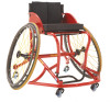

User Manual
Page 2
Sun is a registered trademark of Sun Components, Inc. 3-in part is required for any warranty claims and placing aftermarket parts orders. ©2013 Invacare®Corporation All rights reserved. Shimano is a registered trademark of Shimano, Inc. Du Pont De Nemours and Company ...Please record your serial number SN The SN is prohibited without prior written permission from Invacare. All trademarks are ...
Sun is a registered trademark of Sun Components, Inc. 3-in part is required for any warranty claims and placing aftermarket parts orders. ©2013 Invacare®Corporation All rights reserved. Shimano is a registered trademark of Shimano, Inc. Du Pont De Nemours and Company ...Please record your serial number SN The SN is prohibited without prior written permission from Invacare. All trademarks are ...
User Manual
Page 6
... reading and understanding these instructions and any additional instructional material such as the wheelchair may tip over. 6 1171910-A~15 Invacare products are unable to understand the warnings, cautions or instructions, contact a dealer or technical personnel before using. Check...otherwise, injury or damage may cause the wheelchair to move forward in conjunction with Invacare accessories. Contact Invacare/Carrier for use in the seat. - Also, a qualified technician must perform all parts for use with this wheelchair. If you are not recommended for further instruction. ...
... reading and understanding these instructions and any additional instructional material such as the wheelchair may tip over. 6 1171910-A~15 Invacare products are unable to understand the warnings, cautions or instructions, contact a dealer or technical personnel before using. Check...otherwise, injury or damage may cause the wheelchair to move forward in conjunction with Invacare accessories. Contact Invacare/Carrier for use in the seat. - Also, a qualified technician must perform all parts for use with this wheelchair. If you are not recommended for further instruction. ...
User Manual
Page 9
... casters are clean and free of your wheelchair to a gradual stop . q Check for proper tension by spinning caster; Routine maintenance will reveal loose or worn parts and enhance the smooth operation of moisture. Thereafter follow these maintenance procedures: q Inspect seat and back upholstery for a thorough inspection and servicing. Verify hardware that...
... casters are clean and free of your wheelchair to a gradual stop . q Check for proper tension by spinning caster; Routine maintenance will reveal loose or worn parts and enhance the smooth operation of moisture. Thereafter follow these maintenance procedures: q Inspect seat and back upholstery for a thorough inspection and servicing. Verify hardware that...

User Manual
Page 27
Move anti-tip to desired height above the ground. 4. After installing the adjustable anti-tip wheel, rear wheels may be about a finger's width above ground. The anti-tip should be removed to the anti-tip clamp B. 2. Insert adjustable anti-tip wheel C into base frame D with wheel facing down. 3. With rear wheels on, tighten quick release lever at desired level. 4.4 Installing Adjustable Anti-tip Wheel 1. Release and loosen the quick release lever A attached to prevent the chair from moving while installing other parts. 1171910-A~15 Setup 27
Move anti-tip to desired height above the ground. 4. After installing the adjustable anti-tip wheel, rear wheels may be about a finger's width above ground. The anti-tip should be removed to the anti-tip clamp B. 2. Insert adjustable anti-tip wheel C into base frame D with wheel facing down. 3. With rear wheels on, tighten quick release lever at desired level. 4.4 Installing Adjustable Anti-tip Wheel 1. Release and loosen the quick release lever A attached to prevent the chair from moving while installing other parts. 1171910-A~15 Setup 27

User Manual
Page 33
Insert two bolts A through each two part clamp B. 2. Attach the other side of the foot strap A. 2. Place the foot strap around the front down tube C in the desired position. 3. Separate the hook and loop sections of the two-part clamp to the base frame down tubes of the foot strap. 33 Tighten the clamp using an Allen key E. 4.10 Attaching the Foot strap 1171910-A~15 1. Connect the hook and loop sections of the base frame B in the desired position. 3. Attach the larger side of the two-part clamps to the footrest D. 4. 4.9 Attaching the Footrest Setup 1.
Insert two bolts A through each two part clamp B. 2. Attach the other side of the foot strap A. 2. Place the foot strap around the front down tube C in the desired position. 3. Separate the hook and loop sections of the two-part clamp to the base frame down tubes of the foot strap. 33 Tighten the clamp using an Allen key E. 4.10 Attaching the Foot strap 1171910-A~15 1. Connect the hook and loop sections of the base frame B in the desired position. 3. Attach the larger side of the two-part clamps to the footrest D. 4. 4.9 Attaching the Footrest Setup 1.
User Manual
Page 35
... bumps. DO NOT attempt to practice and master these safe techniques until you from operating the wheelchair properly. 35 DO NOT carry any removable (detachable) parts. The offensive wing design creates a potential foot entrapment area. Avoid all times. Lifting by the end-user - DO NOT attempt to the wheelchair. - Doing so... you are properly secured during use the handrims for failure, damage or injury caused by improper operation or maintenance by means of any removable (detachable) parts of the wheelchair. DO NOT carry any contact sport. -
... bumps. DO NOT attempt to practice and master these safe techniques until you from operating the wheelchair properly. 35 DO NOT carry any removable (detachable) parts. The offensive wing design creates a potential foot entrapment area. Avoid all times. Lifting by the end-user - DO NOT attempt to the wheelchair. - Doing so... you are properly secured during use the handrims for failure, damage or injury caused by improper operation or maintenance by means of any removable (detachable) parts of the wheelchair. DO NOT carry any contact sport. -

User Manual
Page 48
...® Sports Series Schulte 7000/T-5™ 7000 Front Fork and Anti-Tip Fork Stem Assembly Replacement The Front Fork and Anti-Tip Fork Stem Assembly parts may occur. Secure height adjustment brackets C to desired height. 3. Place the empty wheelchair upside down so the bottom of seat to the base frame with...
...® Sports Series Schulte 7000/T-5™ 7000 Front Fork and Anti-Tip Fork Stem Assembly Replacement The Front Fork and Anti-Tip Fork Stem Assembly parts may occur. Secure height adjustment brackets C to desired height. 3. Place the empty wheelchair upside down so the bottom of seat to the base frame with...
User Manual
Page 64
...release axles free of the tire. CAUTION! - Contact a qualified technician or Invacare customer support at the telephone numbers on any moving parts. Check upholstery for damage or wear and replace. Check all parts for cracks and wear, and should be replaced when necessary. DO NOT overinflate... the tires. Contact a qualified technician or Invacare customer support at the telephone numbers ...
...release axles free of the tire. CAUTION! - Contact a qualified technician or Invacare customer support at the telephone numbers on any moving parts. Check upholstery for damage or wear and replace. Check all parts for cracks and wear, and should be replaced when necessary. DO NOT overinflate... the tires. Contact a qualified technician or Invacare customer support at the telephone numbers ...
User Manual
Page 70
...NEGLIGENCE, ACCIDENT, IMPROPER OPERATION, MAINTENANCE OR STORAGE, COMMERCIAL OR INSTITUTIONAL USE, PRODUCTS MODIFIED WITHOUT INVACARE'S EXPRESS WRITTEN CONSENT, INCLUDING, BUT NOT LIMITED TO, MODIFICATION THROUGH THE USE OF UNAUTHORIZED PARTS OR ATTACHMENTS; THE WARRANTY SHALL NOT APPLY TO PROBLEMS ARISING FROM NORMAL WEAR OR FAILURE TO...does not include any labor or shipping charges incurred in materials and workmanship for a period of one year from Invacare or a dealer, with refurbished or new parts. PRODUCTS DAMAGED BY REASON OF REPAIRS MADE TO ANY COMPONENT WITHOUT THE SPECIFIC CONSENT OF...
...NEGLIGENCE, ACCIDENT, IMPROPER OPERATION, MAINTENANCE OR STORAGE, COMMERCIAL OR INSTITUTIONAL USE, PRODUCTS MODIFIED WITHOUT INVACARE'S EXPRESS WRITTEN CONSENT, INCLUDING, BUT NOT LIMITED TO, MODIFICATION THROUGH THE USE OF UNAUTHORIZED PARTS OR ATTACHMENTS; THE WARRANTY SHALL NOT APPLY TO PROBLEMS ARISING FROM NORMAL WEAR OR FAILURE TO...does not include any labor or shipping charges incurred in materials and workmanship for a period of one year from Invacare or a dealer, with refurbished or new parts. PRODUCTS DAMAGED BY REASON OF REPAIRS MADE TO ANY COMPONENT WITHOUT THE SPECIFIC CONSENT OF...

User Manual
Page 72
...Tel: (44) (0)1656 776200, Fax: (44) (0)1656 776201 Customer services Tel: (44) (0)1656 776222, Fax: (44) (0)1656 776220 UK@invacare.com, www.invacare.co.uk 72 1171910-A~15 Canadian limited warranty same as United States limited warranty. E. Box 62-124 Mt. Australia 1 Lenton Place, PO Box 5002....au, www.invacare.com.au Canada 570 Matheson Blvd. Top End® Sports Series 10.2 European, Australian, and New Zealand Limited Warranty and Customer Service Information Customer Service and Limited Warranty Information Terms and conditions of the warranty are part of the general terms and ...
...Tel: (44) (0)1656 776200, Fax: (44) (0)1656 776201 Customer services Tel: (44) (0)1656 776222, Fax: (44) (0)1656 776220 UK@invacare.com, www.invacare.co.uk 72 1171910-A~15 Canadian limited warranty same as United States limited warranty. E. Box 62-124 Mt. Australia 1 Lenton Place, PO Box 5002....au, www.invacare.com.au Canada 570 Matheson Blvd. Top End® Sports Series 10.2 European, Australian, and New Zealand Limited Warranty and Customer Service Information Customer Service and Limited Warranty Information Terms and conditions of the warranty are part of the general terms and ...


