Owners Manual
Page 7
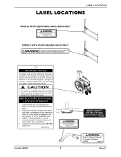
...pneumatic tires). Tighten mounting fastener to the lock position (3/16" for correct locking action BEFORE actual use. 00078X021-0394 Part No 1088909 7 Patriot™ LABEL LOCATIONS LABEL LOCATIONS MODELS WITH ADJUSTABLE ANGLE BACK ONLY MODELS WITH QUICK-RELEASE AXLES ONLY IMPORTANT NOTICE The ...recheck lock shoe embedding. 4. Inspect for pneumatic tires). 3. Loosen wheel lock mounting fastener, which runs through mounting bracket and frame. 2. CAUTION Any wheel lock adjustments should embed wheel lock shoe at the factory to comply with the Veterans Administration functional Standard...
...pneumatic tires). Tighten mounting fastener to the lock position (3/16" for correct locking action BEFORE actual use. 00078X021-0394 Part No 1088909 7 Patriot™ LABEL LOCATIONS LABEL LOCATIONS MODELS WITH ADJUSTABLE ANGLE BACK ONLY MODELS WITH QUICK-RELEASE AXLES ONLY IMPORTANT NOTICE The ...recheck lock shoe embedding. 4. Inspect for pneumatic tires). 3. Loosen wheel lock mounting fastener, which runs through mounting bracket and frame. 2. CAUTION Any wheel lock adjustments should embed wheel lock shoe at the factory to comply with the Veterans Administration functional Standard...
Owners Manual
Page 8
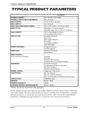
...tires. If wheelchair is equipped with pneumatic tires or pneumatic tires with packaging. NOTE: Invacare recommends that rear seat‐to‐floor heights be at least 3/8‐inch shorter...Adjustable Angle - 85° to the measurements listed above. TYPICAL PRODUCT PARAMETERS TYPICAL PRODUCT PARAMETERS PATRIOT OVERALL WIDTH: OVERALL DEPTH (WITH RIGGINGS) SEAT WIDTH: SEAT DEPTH: SEAT-TO-FLOOR (ADULT... or Pneumatic-Flat Free Insert U240 Black Nylon Patriot - 29 lbs 250 lbs Patriot - 39.5lbs* *NOTE: 16x16 inch Seat Frame with flat free inserts, add ¼ inch to ...
...tires. If wheelchair is equipped with pneumatic tires or pneumatic tires with packaging. NOTE: Invacare recommends that rear seat‐to‐floor heights be at least 3/8‐inch shorter...Adjustable Angle - 85° to the measurements listed above. TYPICAL PRODUCT PARAMETERS TYPICAL PRODUCT PARAMETERS PATRIOT OVERALL WIDTH: OVERALL DEPTH (WITH RIGGINGS) SEAT WIDTH: SEAT DEPTH: SEAT-TO-FLOOR (ADULT... or Pneumatic-Flat Free Insert U240 Black Nylon Patriot - 29 lbs 250 lbs Patriot - 39.5lbs* *NOTE: 16x16 inch Seat Frame with flat free inserts, add ¼ inch to ...
Owners Manual
Page 11
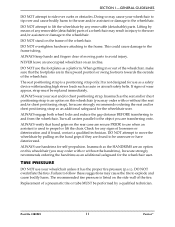
... (you may order with or without the seat and/or chest positioning strap), Invacare strongly recommends ordering the seat and/or chest positioning strap as a platform. ALWAYS... harm to the user and/or assistant or damage to ride over curbs or obstacles. Part No 1088909 11 Patriot™ DO NOT attempt to propel or lift the chair. Inasmuch as auto or aircraft...footrests towards the outside of moving parts to explode and cause bodily harm. DO NOT overtighten hardware attaching to the frame tubing. This could cause damage to the frame. When getting in injury to the...
... (you may order with or without the seat and/or chest positioning strap), Invacare strongly recommends ordering the seat and/or chest positioning strap as a platform. ALWAYS... harm to the user and/or assistant or damage to ride over curbs or obstacles. Part No 1088909 11 Patriot™ DO NOT attempt to propel or lift the chair. Inasmuch as auto or aircraft...footrests towards the outside of moving parts to explode and cause bodily harm. DO NOT overtighten hardware attaching to the frame tubing. This could cause damage to the frame. When getting in injury to the...

Owners Manual
Page 15
... of the wheelchair lifting upward on the sidewalk and turn the wheelchair so that METHOD 2 use two assistants. METHOD 2 WHEELCHAIR WITHOUT STEP TUBES Part No 1088909 15 Patriot™ Unless the first assistant has exceptional upper body strength, it is recommended that the rear wheels are against the curb. METHOD 1 - ...Apply a continuous downward motion until the wheelchair has been pulled backward far enough for the front casters to clear the edge of the wheelchair frame when lifting the wheelchair and stabilizing the wheelchair when the wheelchair is being lowered to the ground.
... of the wheelchair lifting upward on the sidewalk and turn the wheelchair so that METHOD 2 use two assistants. METHOD 2 WHEELCHAIR WITHOUT STEP TUBES Part No 1088909 15 Patriot™ Unless the first assistant has exceptional upper body strength, it is recommended that the rear wheels are against the curb. METHOD 1 - ...Apply a continuous downward motion until the wheelchair has been pulled backward far enough for the front casters to clear the edge of the wheelchair frame when lifting the wheelchair and stabilizing the wheelchair when the wheelchair is being lowered to the ground.
Owners Manual
Page 19
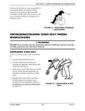
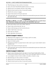
... for clearance and transfer into the wheelchair unless it is fully open and the seat rails are fully seated into the side frame H-blocks. UNFOLDING SLING SEAT Part No 1088909 19 Patriot™ Point front casters forward to Transferring To and From Other Seats on the seat rail closest to you (raising the...
... for clearance and transfer into the wheelchair unless it is fully open and the seat rails are fully seated into the side frame H-blocks. UNFOLDING SLING SEAT Part No 1088909 19 Patriot™ Point front casters forward to Transferring To and From Other Seats on the seat rail closest to you (raising the...
Owners Manual
Page 22
... positioning strap for proper inflation (recommended tire pressure is secure and undamaged. Patriot™ 22 Part No 1088909 INSPECT/ADJUST WEEKLY ❑ Wheelchair rolls straight (no excessive drag or pull to frame is listed on quick-release axles. Verify hardware that attaches strap to one... free of wear and looseness. SECTION 3-SAFETY INSPECTION/TROUBLESHOOTING ❑ Wheel bearings are clean and free of moisture. ❑ Ensure all parts. ❑ Clean upholstery and armrests. Otherwise, binding and/or damage to a stop . ❑ Inspect tires/casters for flat spots ...
... positioning strap for proper inflation (recommended tire pressure is secure and undamaged. Patriot™ 22 Part No 1088909 INSPECT/ADJUST WEEKLY ❑ Wheelchair rolls straight (no excessive drag or pull to frame is listed on quick-release axles. Verify hardware that attaches strap to one... free of wear and looseness. SECTION 3-SAFETY INSPECTION/TROUBLESHOOTING ❑ Wheel bearings are clean and free of moisture. ❑ Ensure all parts. ❑ Clean upholstery and armrests. Otherwise, binding and/or damage to a stop . ❑ Inspect tires/casters for flat spots ...
Owners Manual
Page 25
... all nuts and bolts are clean and free from moisture. Refer to Refer to explode and cause bodily harm. 3. Refer to Refer to the frame tubing. Refer to Using/Adjusting Wheel Locks (Push‐to‐Lock/Pull‐to‐Lock) on page 43. ƽ WARNING DO NOT...to Using/Adjusting High Mount Wheel Locks (Push‐to‐Lock/Pull‐to tire wear. Before using your Patriot, make sure all parts for proper adjustment. 2. Part No 1088909 25 Patriot™ If tires are secured to ensure they are tight. Periodically check handrims to the rear wheels. SECTION 4-...
... all nuts and bolts are clean and free from moisture. Refer to Refer to explode and cause bodily harm. 3. Refer to Refer to the frame tubing. Refer to Using/Adjusting Wheel Locks (Push‐to‐Lock/Pull‐to‐Lock) on page 43. ƽ WARNING DO NOT...to Using/Adjusting High Mount Wheel Locks (Push‐to‐Lock/Pull‐to tire wear. Before using your Patriot, make sure all parts for proper adjustment. 2. Part No 1088909 25 Patriot™ If tires are secured to ensure they are tight. Periodically check handrims to the rear wheels. SECTION 4-...
Owners Manual
Page 27
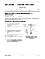
... mounting pin into place. INSTALLING SWINGAWAY FOOTREST 1. Adjust the footrest height, if necessary. INSTALLING/ REMOVING SWINGAWAY FOOTREST Part No 1088909 27 Patriot™ Rotate the footrest towards the inside of the wheelchair when locked in the trailing position. NOTE: 70°...use, make sure all attaching hardware is perpendicular to the wheelchair). 2. Repositioning casters MUST be on page 28 of the wheelchair frame. 3. NOTE: The footplate will be performed by a qualified technician. INSTALLING/REMOVING SWINGAWAY FOOTREST NOTE: For this procedure, refer...
... mounting pin into place. INSTALLING SWINGAWAY FOOTREST 1. Adjust the footrest height, if necessary. INSTALLING/ REMOVING SWINGAWAY FOOTREST Part No 1088909 27 Patriot™ Rotate the footrest towards the inside of the wheelchair when locked in the trailing position. NOTE: 70°...use, make sure all attaching hardware is perpendicular to the wheelchair). 2. Repositioning casters MUST be on page 28 of the wheelchair frame. 3. NOTE: The footplate will be performed by a qualified technician. INSTALLING/REMOVING SWINGAWAY FOOTREST NOTE: For this procedure, refer...

Owners Manual
Page 28
... of the wheelchair, if necessary. ADJUSTING SWINGAWAY FOOTREST HEIGHT 1. Repeat STEPS 1‐5 for the opposite side of the wheelchair frame. 3. Remove the footrest from the footrest upper support. 3. Refer to Installing/ Removing Swingaway Footrest on page 27. 2. SECTION... 5-FRONT RIGGINGS REMOVING SWINGAWAY FOOTREST 1. Push the footrest release lever inward while rotating the footrest outward. 2. Patriot™ 28 Part No 1088909 REMOVING HEEL LOOPS 1. Refer to Installing Heel Loops on its mounting tube until the desired footrest height is...
... of the wheelchair, if necessary. ADJUSTING SWINGAWAY FOOTREST HEIGHT 1. Repeat STEPS 1‐5 for the opposite side of the wheelchair frame. 3. Remove the footrest from the footrest upper support. 3. Refer to Installing/ Removing Swingaway Footrest on page 27. 2. SECTION... 5-FRONT RIGGINGS REMOVING SWINGAWAY FOOTREST 1. Push the footrest release lever inward while rotating the footrest outward. 2. Patriot™ 28 Part No 1088909 REMOVING HEEL LOOPS 1. Refer to Installing Heel Loops on its mounting tube until the desired footrest height is...

Owners Manual
Page 29
...to FIGURE 5.4. Repeat STEPS 1‐3 for opposite legrest assembly. otherwise injury or damage may result. INSTALLING ELEVATING LEGREST 1. Part No 1088909 29 Patriot™ Refer to footrest assembly, tighten the mounting screw and locknut until it with the mounting screw, spacer and locknut.... Insert the footplate assembly into the legrest mounting tube on the wheelchair frame. 3. Secure new heel loop to the footplate ...
...to FIGURE 5.4. Repeat STEPS 1‐3 for opposite legrest assembly. otherwise injury or damage may result. INSTALLING ELEVATING LEGREST 1. Part No 1088909 29 Patriot™ Refer to footrest assembly, tighten the mounting screw and locknut until it with the mounting screw, spacer and locknut.... Insert the footplate assembly into the legrest mounting tube on the wheelchair frame. 3. Secure new heel loop to the footplate ...
Owners Manual
Page 37
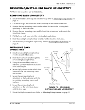
...Armrest on page 33. Refer to Adjusting/Using Armrest on page 37. Secure the new/existing back upholstery to the wheelchair frame. 5. Part No 1088909 37 Patriot™ Cut the tie wraps that secures one back cane to the back canes with the tie wraps. Slide the existing... upholstery. 6. INSTALLING BACK UPHOLSTERY 1. Rotate the flip back arms down. Remove the one mounting screw and locknut. 5. Refer to the wheelchair frame with the two existing mounting screws and washers. 6. Slide the loose back cane through the new/existing back upholstery. 3. Secure the new/existing...
...Armrest on page 33. Refer to Adjusting/Using Armrest on page 37. Secure the new/existing back upholstery to the wheelchair frame. 5. Part No 1088909 37 Patriot™ Cut the tie wraps that secures one back cane to the back canes with the tie wraps. Slide the existing... upholstery. 6. INSTALLING BACK UPHOLSTERY 1. Rotate the flip back arms down. Remove the one mounting screw and locknut. 5. Refer to the wheelchair frame with the two existing mounting screws and washers. 6. Slide the loose back cane through the new/existing back upholstery. 3. Secure the new/existing...
Owners Manual
Page 38
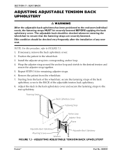
... the back of the wheelchair, secure the fastening straps of any new seat. ADJUSTING ADJUSTABLE TENSION BACK UPHOLSTERY Patriot™ 38 Part No 1088909 Fastening Strap Back Upholstery Cover Fastening Strap Anchor Loop Adjuster Strap Frame Adjustable Back Upholstery Mounting Screws Adjustable Back Upholstery Washers FIGURE 7.3 - Wrap the adjuster strap around the anchor...
... the back of the wheelchair, secure the fastening straps of any new seat. ADJUSTING ADJUSTABLE TENSION BACK UPHOLSTERY Patriot™ 38 Part No 1088909 Fastening Strap Back Upholstery Cover Fastening Strap Anchor Loop Adjuster Strap Frame Adjustable Back Upholstery Mounting Screws Adjustable Back Upholstery Washers FIGURE 7.3 - Wrap the adjuster strap around the anchor...
Owners Manual
Page 42
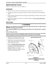
...past the inside of the axle bushing or there is too much movement of the existing rear wheel. 4. Keep locking pins clean. Invacare recommends inserting quick-release axles with the head end to Adjusting Quick‐Release Axles on page 43 if the locking pins are ...existing rear wheel and quick‐release axle into the axle bracket on the wheelchair frame. 3. QUICK-RELEASE AXLES Rear Wheel Wheelchair Frame Patriot™ Quick-Release Axle Axle Bracket FIGURE 8.2 REMOVING/INSTALLING REAR WHEELS 42 Part No 1088909 Push in the tip of rear wheel hub for a positive lock....
...past the inside of the axle bushing or there is too much movement of the existing rear wheel. 4. Keep locking pins clean. Invacare recommends inserting quick-release axles with the head end to Adjusting Quick‐Release Axles on page 43 if the locking pins are ...existing rear wheel and quick‐release axle into the axle bracket on the wheelchair frame. 3. QUICK-RELEASE AXLES Rear Wheel Wheelchair Frame Patriot™ Quick-Release Axle Axle Bracket FIGURE 8.2 REMOVING/INSTALLING REAR WHEELS 42 Part No 1088909 Push in the tip of rear wheel hub for a positive lock....
Owners Manual
Page 43
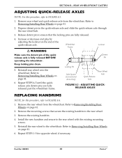
... the quick‐release axle. ƽ WARNING Make sure the detent pin of the quick release axle is fully released BEFORE operating the wheelchair. Wheelchair Frame Locknut Detent Pin Keep locking pins clean. 5. Reinstall rear wheel onto the wheelchair. Repeat STEPS 4‐5 until the quick release axle detent pins are .... Refer to the rear wheel with the existing mounting screws. 5. FIGURE 8.3 - Remove the mounting screws that the locking pins are fully released past the wheelchair frame. Reinstall the rear wheel to the wheelchair. Part No 1088909 43 Patriot™
... the quick‐release axle. ƽ WARNING Make sure the detent pin of the quick release axle is fully released BEFORE operating the wheelchair. Wheelchair Frame Locknut Detent Pin Keep locking pins clean. 5. Reinstall rear wheel onto the wheelchair. Repeat STEPS 4‐5 until the quick release axle detent pins are .... Refer to the rear wheel with the existing mounting screws. 5. FIGURE 8.3 - Remove the mounting screws that the locking pins are fully released past the wheelchair frame. Reinstall the rear wheel to the wheelchair. Part No 1088909 43 Patriot™
Owners Manual
Page 46
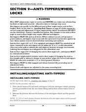
...189; to -floor angle): If changing the seat-tofloor height with or without the anti-tippers), Invacare strongly recommends ordering the anti-tippers as the anti-tippers are adjusted to -floor heights. Seat-...and the ground/ floor MUST be maintained at all attaching hardware is tightened securely - Patriot™ 46 Part No 1088909 SECTION 9-ANTI-TIPPERS/WHEEL LOCKS SECTION 9-ANTI-TIPPERS/WHEEL LOCKS ƽ ... may order with the anti‐tipper wheels pointing toward ground/floor into the rear frame tubing until bottom release button locks in - Seat-to -floor angle, the correct anti...
...189; to -floor angle): If changing the seat-tofloor height with or without the anti-tippers), Invacare strongly recommends ordering the anti-tippers as the anti-tippers are adjusted to -floor heights. Seat-...and the ground/ floor MUST be maintained at all attaching hardware is tightened securely - Patriot™ 46 Part No 1088909 SECTION 9-ANTI-TIPPERS/WHEEL LOCKS SECTION 9-ANTI-TIPPERS/WHEEL LOCKS ƽ ... may order with the anti‐tipper wheels pointing toward ground/floor into the rear frame tubing until bottom release button locks in - Seat-to -floor angle, the correct anti...
Owners Manual
Page 47
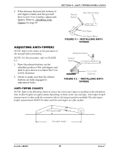
... ‐floor heights are fully engaged in the wheelchair. Seat‐to 2 inch Clearance FIGURE 9.2 - - Release Buttons Rear Frame Tubing Anti-Tipper ADJUSTING ANTI-TIPPERS NOTE: Refer to ensure the correct anti‐tipper is installed in adjustment holes. INSTALLING ANTITIPPERS ANTI... be taken with the anti‐tipper on page 47. SECTION 9-ANTI-TIPPERS/WHEEL LOCKS 3. Anti-tipper Height Anti-tipper Length Part No 1088909 47 Patriot™ Anti-Tipper Wheel FIGURE 9.1 - NOTE: For this procedure of the manual before proceeding. Press the release buttons on front...
... ‐floor heights are fully engaged in the wheelchair. Seat‐to 2 inch Clearance FIGURE 9.2 - - Release Buttons Rear Frame Tubing Anti-Tipper ADJUSTING ANTI-TIPPERS NOTE: Refer to ensure the correct anti‐tipper is installed in adjustment holes. INSTALLING ANTITIPPERS ANTI... be taken with the anti‐tipper on page 47. SECTION 9-ANTI-TIPPERS/WHEEL LOCKS 3. Anti-tipper Height Anti-tipper Length Part No 1088909 47 Patriot™ Anti-Tipper Wheel FIGURE 9.1 - NOTE: For this procedure of the manual before proceeding. Press the release buttons on front...
Owners Manual
Page 49
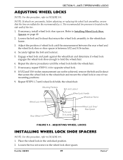
...until the wheel lock holds the wheelchair. 7. Mounting Positions Wheel Lock Rear Wheel Bolt and Locknut Wheel Lock Handle Wheelchair Frame 5/32 and 5/16-inches Wheel Lock Shoe/ Shoe Spacer FIGURE 9.4 - SECTION 9-ANTI-TIPPERS/WHEEL LOCKS ADJUSTING WHEEL...Place the wheel lock in the wheel lock shoe spacer. NOTE: If wheels are inflated to the wheelchair frame. 3. Engage wheel lock and push against the wheelchair and determine if wheel lock engages the wheel lock...the bolt and locknut that secure the wheel lock assembly to the recommended p.s.i. Part No 1088909 49 Patriot™
...until the wheel lock holds the wheelchair. 7. Mounting Positions Wheel Lock Rear Wheel Bolt and Locknut Wheel Lock Handle Wheelchair Frame 5/32 and 5/16-inches Wheel Lock Shoe/ Shoe Spacer FIGURE 9.4 - SECTION 9-ANTI-TIPPERS/WHEEL LOCKS ADJUSTING WHEEL...Place the wheel lock in the wheel lock shoe spacer. NOTE: If wheels are inflated to the wheelchair frame. 3. Engage wheel lock and push against the wheelchair and determine if wheel lock engages the wheel lock...the bolt and locknut that secure the wheel lock assembly to the recommended p.s.i. Part No 1088909 49 Patriot™
Owners Manual
Page 51
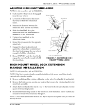
... handles. 1. NOTE: Cord is made of the existing handle. 4. Socket Screws Wheelchair Frame 3. Reassemble the existing handle to secure the cord around the spacer. Part No 1088909 51 Patriot™ SECTION 9-ANTI-TIPPERS/WHEEL LOCKS ADJUSTING HIGH MOUNT WHEEL LOCKS NOTE: For this procedure..., refer to the wheelchair frame. 6. Tighten the wheel lock to FIGURE 9.7. 1. Repeat STEPS 1‐...
... handles. 1. NOTE: Cord is made of the existing handle. 4. Socket Screws Wheelchair Frame 3. Reassemble the existing handle to secure the cord around the spacer. Part No 1088909 51 Patriot™ SECTION 9-ANTI-TIPPERS/WHEEL LOCKS ADJUSTING HIGH MOUNT WHEEL LOCKS NOTE: For this procedure..., refer to the wheelchair frame. 6. Tighten the wheel lock to FIGURE 9.7. 1. Repeat STEPS 1‐...
Owners Manual
Page 53
...Invacare at Invacare's option. Invacare's sole obligation and your Invacare product. THE APPLICATION OF ANY IMPLIED WARRANTY WHATSOEVER SHALL NOT EXTEND BEYOND THE DURATION OF THE EXPRESS WARRANTY PROVIDED HEREIN. THIS WARRANTY SHALL BE EXTENDED TO COMPLY WITH STATE/PROVINCIAL LAWS AND REQUIREMENTS. Part No 1088909 53 Patriot...OF INVACARE, OR TO A PRODUCT DAMAGED BY CIRCUMSTANCES BEYOND INVACARE'S CONTROL, AND SUCH EVALUATION WILL BE SOLELY DETERMINED BY INVACARE. The side frames and crossmembers are warranted for a period of one year from defects in replacement part ...
...Invacare at Invacare's option. Invacare's sole obligation and your Invacare product. THE APPLICATION OF ANY IMPLIED WARRANTY WHATSOEVER SHALL NOT EXTEND BEYOND THE DURATION OF THE EXPRESS WARRANTY PROVIDED HEREIN. THIS WARRANTY SHALL BE EXTENDED TO COMPLY WITH STATE/PROVINCIAL LAWS AND REQUIREMENTS. Part No 1088909 53 Patriot...OF INVACARE, OR TO A PRODUCT DAMAGED BY CIRCUMSTANCES BEYOND INVACARE'S CONTROL, AND SUCH EVALUATION WILL BE SOLELY DETERMINED BY INVACARE. The side frames and crossmembers are warranted for a period of one year from defects in replacement part ...


