Design Guide
Page 21
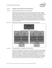
... domains to a PECI domain. Figure 2-5 provides an illustration of the DTS output temperatures within the processor currently maps to the thermal management system. The PECI signal is available through CPU pin (G5) on TCONTROL. The Quad-Core Intel® Xeon® Processor 5300 Series contains two dies (Domains) and each other. An external PECI device that is...
... domains to a PECI domain. Figure 2-5 provides an illustration of the DTS output temperatures within the processor currently maps to the thermal management system. The PECI signal is available through CPU pin (G5) on TCONTROL. The Quad-Core Intel® Xeon® Processor 5300 Series contains two dies (Domains) and each other. An external PECI device that is...
Design Guide
Page 52
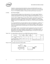
... not used, pin 3 of the processor socket. If a 3-pin CPU fan header is recommended that can send a PWM signal to reach it. The fan power header identification and location must be tied to support the boxed processor. Table 2-10. Fan Cable Connection (Active CEK) 52 Quad-Core Intel® Xeon® Processor 5300 Series Thermal/Mechanical Design Guidelines...
... not used, pin 3 of the processor socket. If a 3-pin CPU fan header is recommended that can send a PWM signal to reach it. The fan power header identification and location must be tied to support the boxed processor. Table 2-10. Fan Cable Connection (Active CEK) 52 Quad-Core Intel® Xeon® Processor 5300 Series Thermal/Mechanical Design Guidelines...
