Product Guide
Page 3
...BIOS error messages and beep codes. Appendix A, "Error Messages and Indicators" provides information about configuring your system for Intended Applications All Intel Boards are arranged as Information Technology Equipment (I.T.E.) for use in personal computers (PC) for installation in this product for the Intel® Workstation Board WX58BP.... It is intended for general audiences. Use Only for RAID. Appendix B, "Regulatory Compliance" describes the board's adherence to safety standards and EMC regulations...
...BIOS error messages and beep codes. Appendix A, "Error Messages and Indicators" provides information about configuring your system for Intended Applications All Intel Boards are arranged as Information Technology Equipment (I.T.E.) for use in personal computers (PC) for installation in this product for the Intel® Workstation Board WX58BP.... It is intended for general audiences. Use Only for RAID. Appendix B, "Regulatory Compliance" describes the board's adherence to safety standards and EMC regulations...

Product Guide
Page 5
... 9 Supported Operating Systems 10 Board Components 11 Processor ...13 Main Memory ...14 Intel® X58 Express Chipset 15 Audio Subsystem 15 LAN Subsystem 16 USB 2.0 Support 17 Serial ATA...17 Legacy I/O ...17 Expandability...17 BIOS ...18 Serial ATA and IDE Auto Configuration 18 PCI...STAR* Capable 23 Onboard VR and CPU LEDs 23 Speaker...24 Battery ...24 Real-Time Clock 24 2 Installing and Replacing Workstation Board Components ...........25 Before You Begin 25 Installation Precautions 26 Prevent Power Supply Overload 26 Observe Safety and Regulatory Requirements 26 Installing ...
... 9 Supported Operating Systems 10 Board Components 11 Processor ...13 Main Memory ...14 Intel® X58 Express Chipset 15 Audio Subsystem 15 LAN Subsystem 16 USB 2.0 Support 17 Serial ATA...17 Legacy I/O ...17 Expandability...17 BIOS ...18 Serial ATA and IDE Auto Configuration 18 PCI...STAR* Capable 23 Onboard VR and CPU LEDs 23 Speaker...24 Battery ...24 Real-Time Clock 24 2 Installing and Replacing Workstation Board Components ...........25 Before You Begin 25 Installation Precautions 26 Prevent Power Supply Overload 26 Observe Safety and Regulatory Requirements 26 Installing ...
Product Guide
Page 6
Intel® Workstation Board WX58BP Product Guide Installing the Processor Fan Heatsink 33 Connecting the Processor Fan Heatsink Cable 33 Removing the Processor 34 Installing and Removing Memory 35 Guidelines ... Chassis Fan Cables 49 Connecting Power Supply Cables 50 Setting the BIOS Configuration Jumper 51 Clearing Passwords 52 Replacing the Battery 53 3 Updating the BIOS 58 Updating the BIOS with the Intel® Express BIOS Update Utility 58 Updating the BIOS with the ISO Image BIOS Update File or the Iflash Memory Update Utility ...59 Obtaining the...
Intel® Workstation Board WX58BP Product Guide Installing the Processor Fan Heatsink 33 Connecting the Processor Fan Heatsink Cable 33 Removing the Processor 34 Installing and Removing Memory 35 Guidelines ... Chassis Fan Cables 49 Connecting Power Supply Cables 50 Setting the BIOS Configuration Jumper 51 Clearing Passwords 52 Replacing the Battery 53 3 Updating the BIOS 58 Updating the BIOS with the Intel® Express BIOS Update Utility 58 Updating the BIOS with the ISO Image BIOS Update File or the Iflash Memory Update Utility ...59 Obtaining the...
Product Guide
Page 7
... Figure 17. Use DDR3 DIMMs 36 Figure 18. Back Panel Audio Connectors 48 Figure 25. Location of the BIOS Configuration Jumper Block 51 Figure 28. Triple Channel Memory Configuration 35 Figure 15. Intel® Workstation Board WX58BP China RoHS Material Self Declaration Table ...73 Tables Table 1. Lift the Load Plate 30 Figure 9. Installing a PCI Express...
... Figure 17. Use DDR3 DIMMs 36 Figure 18. Back Panel Audio Connectors 48 Figure 25. Location of the BIOS Configuration Jumper Block 51 Figure 28. Triple Channel Memory Configuration 35 Figure 15. Intel® Workstation Board WX58BP China RoHS Material Self Declaration Table ...73 Tables Table 1. Lift the Load Plate 30 Figure 9. Installing a PCI Express...
Product Guide
Page 8
Intel® Workstation Board WX58BP Product Guide Table 3. LAN Connector LEDs 16 Table 4. IEEE 1394a Header Signal Names 45 Table 8. Jumper Settings for the BIOS Setup Program Modes 52 Table 13. Lead-Free Second Level Interconnect Marks 71 Table 17. USB 2.0 Header Signal Names... 46 Table 9. S/PDIF Connector Signal Names 47 Table 12. Chassis Intrusion Header Signal Names 45 Table 7. BIOS Error Messages 64 Table 15. China RoHS Environmentally Friendly Use Period Mark 72 Table 18. Front Panel Audio Header Signal Names 44 Table ...
Intel® Workstation Board WX58BP Product Guide Table 3. LAN Connector LEDs 16 Table 4. IEEE 1394a Header Signal Names 45 Table 8. Jumper Settings for the BIOS Setup Program Modes 52 Table 13. Lead-Free Second Level Interconnect Marks 71 Table 17. USB 2.0 Header Signal Names... 46 Table 9. S/PDIF Connector Signal Names 47 Table 12. Chassis Intrusion Header Signal Names 45 Table 7. BIOS Error Messages 64 Table 15. China RoHS Environmentally Friendly Use Period Mark 72 Table 18. Front Panel Audio Header Signal Names 44 Table ...
Product Guide
Page 9
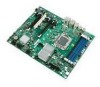
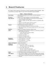
...PCI* bus connector Legacy I /O Support Peripheral Interfaces RAID LAN Support BIOS Table 1. Feature Summary ATX (304.80 millimeters [12.00 inches] x 243.84 millimeters [9.60 inches]) Support for an Intel® processor in the LGA1366 package Four 240-pin DDR3...back panel connector with integrated status LEDs Intel® Platform Innovation Framework for up to 16 GB of system memory Intel® X58 Express Chipset consisting of the Intel® Workstation Board WX58BP. 1 Board Features This chapter briefly describes the features of Intel® Workstation Board DX58SO.
...PCI* bus connector Legacy I /O Support Peripheral Interfaces RAID LAN Support BIOS Table 1. Feature Summary ATX (304.80 millimeters [12.00 inches] x 243.84 millimeters [9.60 inches]) Support for an Intel® processor in the LGA1366 package Four 240-pin DDR3...back panel connector with integrated status LEDs Intel® Platform Innovation Framework for up to 16 GB of system memory Intel® X58 Express Chipset consisting of the Intel® Workstation Board WX58BP. 1 Board Features This chapter briefly describes the features of Intel® Workstation Board DX58SO.
Product Guide
Page 10
...; Voltage sensing to detect out of range values Related Links: For more information about the Intel® Workstation Board WX58BP, including the Technical Product Specification (TPS), BIOS updates, and device drivers, go to: http://support.intel.com/support/motherboards/ Supported Operating Systems The Board supports the following operating systems: Microsoft Windows Vista Ultimate* Microsoft Windows Vista...
...; Voltage sensing to detect out of range values Related Links: For more information about the Intel® Workstation Board WX58BP, including the Technical Product Specification (TPS), BIOS updates, and device drivers, go to: http://support.intel.com/support/motherboards/ Supported Operating Systems The Board supports the following operating systems: Microsoft Windows Vista Ultimate* Microsoft Windows Vista...
Product Guide
Page 14
... GB maximum total system memory NOTE 32-bit operating systems are limited to a maximum of 4 GB of memory. The Intel® Workstation Board WX58BP supports the following links or pages for single-, dual-, and triple-channel memory interleaving Unbuffered, non-registered single ...", page 35 in graphics cards. Intel® Workstation Board WX58BP Product Guide Main Memory NOTE To be fully compliant with all applicable Intel ® SDRAM memory specifications, you will attempt to configure the memory controller for normal operation. The BIOS will see a notification to this effect...
... GB maximum total system memory NOTE 32-bit operating systems are limited to a maximum of 4 GB of memory. The Intel® Workstation Board WX58BP supports the following links or pages for single-, dual-, and triple-channel memory interleaving Unbuffered, non-registered single ...", page 35 in graphics cards. Intel® Workstation Board WX58BP Product Guide Main Memory NOTE To be fully compliant with all applicable Intel ® SDRAM memory specifications, you will attempt to configure the memory controller for normal operation. The BIOS will see a notification to this effect...
Product Guide
Page 17
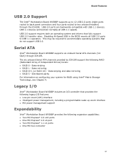
... 2.0 support requires both an operating system and drivers that do not support USB 2.0. Disabling Hi-Speed USB in the BIOS reverts all USB 2.0 ports to two onboard headers) through ICH10R. Serial ATA Intel® Workstation Board WX58BP supports six onboard Serial ATA channels (3.0 Gb/s) through the ICH10R. This may be required to accommodate operating systems...
... 2.0 support requires both an operating system and drivers that do not support USB 2.0. Disabling Hi-Speed USB in the BIOS reverts all USB 2.0 ports to two onboard headers) through ICH10R. Serial ATA Intel® Workstation Board WX58BP supports six onboard Serial ATA channels (3.0 Gb/s) through the ICH10R. This may be required to accommodate operating systems...
Product Guide
Page 18
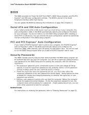
...options. Before the computer boots, the password prompt displays. If only the supervisor password is set , you can update the BIOS by specifying manual configuration in your computer. Related Links: For instructions on whether the supervisor or user password was entered. &#...the supervisor and user passwords are set a supervisor password and a user password for the BIOS Setup and for a password. Intel® Workstation Board WX58BP Product Guide BIOS The BIOS provides the Power-On Self-Test (POST), BIOS Setup program, and PCI/PCI Express* and IDE auto-configuration utilities.
...options. Before the computer boots, the password prompt displays. If only the supervisor password is set , you can update the BIOS by specifying manual configuration in your computer. Related Links: For instructions on whether the supervisor or user password was entered. &#...the supervisor and user passwords are set a supervisor password and a user password for the BIOS Setup and for a password. Intel® Workstation Board WX58BP Product Guide BIOS The BIOS provides the Power-On Self-Test (POST), BIOS Setup program, and PCI/PCI Express* and IDE auto-configuration utilities.

Product Guide
Page 20
.... See Figure 26 on or off when the computer is as needed. All fan headers have a +12 V DC connection. Intel® Workstation Board WX58BP Product Guide ENERGY STAR capable Software Support ACPI ACPI gives the operating system direct control over the power management and Plug and Play ... computer receives the correct command, the power supply removes all non-standby voltages. Failure to the power state it was in the BIOS Setup program's Boot menu. The Board has a 4-pin processor fan header, one 4-pin and two 3-pin chassis fan headers, and one 3-pin IOH fan header....
.... See Figure 26 on or off when the computer is as needed. All fan headers have a +12 V DC connection. Intel® Workstation Board WX58BP Product Guide ENERGY STAR capable Software Support ACPI ACPI gives the operating system direct control over the power management and Plug and Play ... computer receives the correct command, the power supply removes all non-standby voltages. Failure to the power state it was in the BIOS Setup program's Boot menu. The Board has a 4-pin processor fan header, one 4-pin and two 3-pin chassis fan headers, and one 3-pin IOH fan header....
Product Guide
Page 25
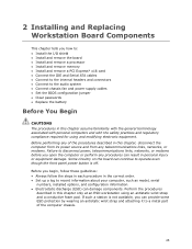
...for using an antistatic wrist strap and a conductive foam pad. 2 Installing and Replacing Workstation Board Components This chapter tells you how to: Install the I/O shield Install and remove the board Install and remove a processor Install and remove memory ... chassis fan and power supply cables Set the BIOS configuration jumper Clear passwords Replace the battery Before You Begin CAUTIONS The procedures in this chapter only at an ESD workstation using and modifying electronic equipment. Before you begin, follow ...
...for using an antistatic wrist strap and a conductive foam pad. 2 Installing and Replacing Workstation Board Components This chapter tells you how to: Install the I/O shield Install and remove the board Install and remove a processor Install and remove memory ... chassis fan and power supply cables Set the BIOS configuration jumper Clear passwords Replace the battery Before You Begin CAUTIONS The procedures in this chapter only at an ESD workstation using and modifying electronic equipment. Before you begin, follow ...

Product Guide
Page 27
...from dust and foreign objects, and promotes correct airflow within the chassis. You must install the I/O shield before installing the Workstation Board in the chassis, the shield blocks radio frequency transmissions, protects internal components from the chassis supplier. Press the shield into place... so it fits tightly and securely. Installing the I /O shield. Updating the BIOS Installing the I/O Shield The Workstation Board comes with an I /O Shield 27 When installed in the chassis. Place the shield inside the chassis as shown in ...
...from dust and foreign objects, and promotes correct airflow within the chassis. You must install the I/O shield before installing the Workstation Board in the chassis, the shield blocks radio frequency transmissions, protects internal components from the chassis supplier. Press the shield into place... so it fits tightly and securely. Installing the I /O shield. Updating the BIOS Installing the I/O Shield The Workstation Board comes with an I /O Shield 27 When installed in the chassis. Place the shield inside the chassis as shown in ...

Product Guide
Page 29
... to install the processor on page 22). Updating the BIOS Installing and Removing a Processor The following section provides instructions on how to do so could damage the processor and the board. the standby power LED should not be lit (see Figure 3 on the Intel® Workstation Board WX58BP. Observe the precautions in "Before You Begin" on...
... to install the processor on page 22). Updating the BIOS Installing and Removing a Processor The following section provides instructions on how to do so could damage the processor and the board. the standby power LED should not be lit (see Figure 3 on the Intel® Workstation Board WX58BP. Observe the precautions in "Before You Begin" on...

Product Guide
Page 31
... the socket. Lower the processor straight down without tilting or sliding it in Figure 11. Remove the processor from the Protective Processor Cover 6. Updating the BIOS 5. Hold the processor only at the edges, being careful not to the socket cutouts (Figure 11, A). Do not discard the protective processor cover. If the...
... the socket. Lower the processor straight down without tilting or sliding it in Figure 11. Remove the processor from the Protective Processor Cover 6. Updating the BIOS 5. Hold the processor only at the edges, being careful not to the socket cutouts (Figure 11, A). Do not discard the protective processor cover. If the...
Product Guide
Page 33
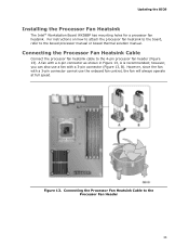
... Fan Heatsink Cable to the 4-pin processor fan header (Figure 13). A fan with a 4-pin connector as shown in Figure 13, A is recommended; Updating the BIOS Installing the Processor Fan Heatsink The Intel® Workstation Board WX58BP has mounting holes for a processor fan heatsink. For instructions on how to attach the processor fan heatsink to the...
... Fan Heatsink Cable to the 4-pin processor fan header (Figure 13). A fan with a 4-pin connector as shown in Figure 13, A is recommended; Updating the BIOS Installing the Processor Fan Heatsink The Intel® Workstation Board WX58BP has mounting holes for a processor fan heatsink. For instructions on how to attach the processor fan heatsink to the...

Product Guide
Page 35
... equal speed and size in the blue DIMM slots (Channel A, DIMM 0, Channel B, and Channel C) as shown in three channels (A, B, and C). Updating the BIOS Installing and Removing Memory The Intel® Workstation Board WX58BP has four 240-pin DDR3 DIMM sockets arranged in Figure 15. Channel A shares two sockets (DIMM 0 and DIMM 1) and Channels B and C have...
... equal speed and size in the blue DIMM slots (Channel A, DIMM 0, Channel B, and Channel C) as shown in three channels (A, B, and C). Updating the BIOS Installing and Removing Memory The Intel® Workstation Board WX58BP has four 240-pin DDR3 DIMM sockets arranged in Figure 15. Channel A shares two sockets (DIMM 0 and DIMM 1) and Channels B and C have...

Product Guide
Page 37
Updating the BIOS NOTE Using a DIMM with the keys in the socket (see Figure 18). Align the small notch at either end of the DIMM until the retaining ...
Updating the BIOS NOTE Using a DIMM with the keys in the socket (see Figure 18). Align the small notch at either end of the DIMM until the retaining ...

Product Guide
Page 39
Updating the BIOS Installing and Removing a PCI Express* x16 Card CAUTION When installing a PCI Express* card on the Intel® Workstation Board WX58BP, ensure the card is not fully seated in the connector, an electrical short may be damaged. Depending on the system. Figure 19. ... x16 graphics cards, install them in the PCI Express* connector before you power on the over-current protection of the power supply, certain board components and/or traces may result across the connector pins. Installing Multiple PCI Express* x16 Graphics Cards 39 Installing Multiple PCI Express* x16 ...
Updating the BIOS Installing and Removing a PCI Express* x16 Card CAUTION When installing a PCI Express* card on the Intel® Workstation Board WX58BP, ensure the card is not fully seated in the connector, an electrical short may be damaged. Depending on the system. Figure 19. ... x16 graphics cards, install them in the PCI Express* connector before you power on the over-current protection of the power supply, certain board components and/or traces may result across the connector pins. Installing Multiple PCI Express* x16 Graphics Cards 39 Installing Multiple PCI Express* x16 ...

Product Guide
Page 41
Figure 21. Remove the screw (Figure 21, A) that secures the card's metal bracket to remove a PCI Express x16 card from the connector (C). 4. Observe the precautions in the notch. This releases the card from a connector: 1. Removing a PCI Express x16 Card 41 Push the card ejector lever down using the tip of a pencil or similar tool (Figure 21, B) in "Before You Begin" on page 25. 2. Pull the card straight up. Updating the BIOS Removing a PCI Express* x16 Card Follow these instructions to the chassis back panel. 3.
Figure 21. Remove the screw (Figure 21, A) that secures the card's metal bracket to remove a PCI Express x16 card from the connector (C). 4. Observe the precautions in the notch. This releases the card from a connector: 1. Removing a PCI Express x16 Card 41 Push the card ejector lever down using the tip of a pencil or similar tool (Figure 21, B) in "Before You Begin" on page 25. 2. Pull the card straight up. Updating the BIOS Removing a PCI Express* x16 Card Follow these instructions to the chassis back panel. 3.


