
Product Guide
Page 3
Contents 1 Description Server Board Features ...7 Back Panel Connectors 8 Server Board Connector and Component Locations 9 Processor ...10 Memory ...10 Add-in Board Slots ...11 Video ...12 SCSI Controller ...12 IDE Controller...12 Network Controller...13 Network Teaming Features 13 Keyboard and Mouse ...15 ACPI ...15 Security ...16 ...
Contents 1 Description Server Board Features ...7 Back Panel Connectors 8 Server Board Connector and Component Locations 9 Processor ...10 Memory ...10 Add-in Board Slots ...11 Video ...12 SCSI Controller ...12 IDE Controller...12 Network Controller...13 Network Teaming Features 13 Keyboard and Mouse ...15 ACPI ...15 Security ...16 ...

Product Guide
Page 5
......24 9. Installing a VRM ...28 13. Server Board Features 7 2. Configuration Jumper (1L4 66 8. Installing DIMMs ...20 4. Place the Heatsink...24 8. Insert the Processor 23 6. Configuration Jumper (1J15 65 7. Connect the Processor Fan 25 10. Processor Clock Speed Jumper 26 11. Software Security Features......77 Figures 1. Problems with Application Software 64 Bootable CD-ROM Is Not Detected 64 5 Technical Reference Server Board Jumpers...65 6 Regulatory and Integration Information Product Regulatory Compliance 67 Product Safety Compliance 67 Product EMC Compliance...
......24 9. Installing a VRM ...28 13. Server Board Features 7 2. Configuration Jumper (1L4 66 8. Installing DIMMs ...20 4. Place the Heatsink...24 8. Insert the Processor 23 6. Configuration Jumper (1J15 65 7. Connect the Processor Fan 25 10. Processor Clock Speed Jumper 26 11. Software Security Features......77 Figures 1. Problems with Application Software 64 Bootable CD-ROM Is Not Detected 64 5 Technical Reference Server Board Jumpers...65 6 Regulatory and Integration Information Product Regulatory Compliance 67 Product Safety Compliance 67 Product EMC Compliance...

Product Guide
Page 7
... MHz, 3.3V, PC/133 compliant, registered, ECC, SDRAM dual inline memory modules (DIMM). Adaptec† AIC- System I /O back panel. Server Board Features Feature Description Processor Up to two Intel® Pentium® III processors in boards. Memory (DRAM) Four 72 bit sockets for add-in a Flip Chip Pin Grid Array (FC-PGA) package. VGA video port...
... MHz, 3.3V, PC/133 compliant, registered, ECC, SDRAM dual inline memory modules (DIMM). Adaptec† AIC- System I /O back panel. Server Board Features Feature Description Processor Up to two Intel® Pentium® III processors in boards. Memory (DRAM) Four 72 bit sockets for add-in a Flip Chip Pin Grid Array (FC-PGA) package. VGA video port...

Product Guide
Page 9
Main power connector (P33) N. Front panel connector(P23) C. Secondary processor (P14) F. Configuration jumper block (1L4) G. Power supply signal connector (P37) H. Two pin speaker connector (P31) L. System fan connector FAN3A (P29) M. Server Board Connector and Component Locations Description 9 Server Board Connector and Component Locations A B C D EF G H AA I . System fan connector FAN2A (P27) B. VRM socket (P32) O. Floppy drive connector...
Main power connector (P33) N. Front panel connector(P23) C. Secondary processor (P14) F. Configuration jumper block (1L4) G. Power supply signal connector (P37) H. Two pin speaker connector (P31) L. System fan connector FAN3A (P29) M. Server Board Connector and Component Locations Description 9 Server Board Connector and Component Locations A B C D EF G H AA I . System fan connector FAN2A (P27) B. VRM socket (P32) O. Floppy drive connector...

Product Guide
Page 10
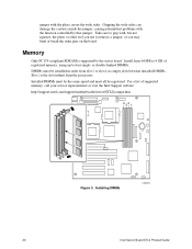
... reports memory size and allocation to slot 4. Contact your sales representative or dealer for the latest tested memory list: http://support.intel.com/support/motherboards/server/STL2/compat.htm 10 Intel Server Board STL2 Product Guide The processor external interface operates at a maximum of noninterleaved memory (64-bit main memory plus ECC). The controller automatically detects, sizes, and initializes...
... reports memory size and allocation to slot 4. Contact your sales representative or dealer for the latest tested memory list: http://support.intel.com/support/motherboards/server/STL2/compat.htm 10 Intel Server Board STL2 Product Guide The processor external interface operates at a maximum of noninterleaved memory (64-bit main memory plus ECC). The controller automatically detects, sizes, and initializes...

Product Guide
Page 15
... s4: Hibernate or Save to Disk: The memory and machine state are running state. • s1: Processor sleep state. With future versions of four PRO/100 Intelligent Server adapters. However, the power supply will be on each adapter and balances network traffic across the adapters as defined...is no hardware changes have two or four PRO/100 Intelligent Server adapters installed in this state. The server may be configured to disk. ACPI The STL2 supports the Advanced Configuration and Power Interface (ACPI) as needed. The STL2 supports sleep states s0, s1, s4, and s5. ...
... s4: Hibernate or Save to Disk: The memory and machine state are running state. • s1: Processor sleep state. With future versions of four PRO/100 Intelligent Server adapters. However, the power supply will be on each adapter and balances network traffic across the adapters as defined...is no hardware changes have two or four PRO/100 Intelligent Server adapters installed in this state. The server may be configured to disk. ACPI The STL2 supports the Advanced Configuration and Power Interface (ACPI) as needed. The STL2 supports sleep states s0, s1, s4, and s5. ...
Product Guide
Page 20
For a list of registered memory, using up to four single- Install from the processors. Installing DIMMs OM10673 20 Intel Server Board STL2 Product Guide Take care to grip with the pliers, never the wide sides. or double-banked DIMMs. DIMMs ... call your service representative or visit the Intel Support website: http://support.intel.com/support/motherboards/server/STL2/compat.htm 4321 Figure 3. Gripping the wide sides can damage the contacts inside the jumper, causing intermittent problems with the function controlled by the server board. Installed DIMMs must be the same speed...
For a list of registered memory, using up to four single- Install from the processors. Installing DIMMs OM10673 20 Intel Server Board STL2 Product Guide Take care to grip with the pliers, never the wide sides. or double-banked DIMMs. DIMMs ... call your service representative or visit the Intel Support website: http://support.intel.com/support/motherboards/server/STL2/compat.htm 4321 Figure 3. Gripping the wide sides can damage the contacts inside the jumper, causing intermittent problems with the function controlled by the server board. Installed DIMMs must be the same speed...
Product Guide
Page 21
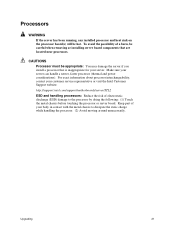
..., contact your customer service representative or visit the Intel Customer Support website: http://support.intel.com/support/motherboards/server/STL2 ESD and handling processors: Reduce the risk of a burn, be careful when removing or installing server board components that is inappropriate for your server. Keep part of your server can handle a newer, faster processor (thermal and power considerations). Make sure your...
..., contact your customer service representative or visit the Intel Customer Support website: http://support.intel.com/support/motherboards/server/STL2 ESD and handling processors: Reduce the risk of a burn, be careful when removing or installing server board components that is inappropriate for your server. Keep part of your server can handle a newer, faster processor (thermal and power considerations). Make sure your...

Product Guide
Page 22
... processor to your system or chassis documentation for specifics). 1. The second processor must first remove the terminator from the secondary processor socket. Observe the safety and ESD precautions at the beginning of the processor with the first processor (within one stepping, same voltage, same speed, see your system, you can set the jumpers correctly. 22 Intel Server Board STL2...
... processor to your system or chassis documentation for specifics). 1. The second processor must first remove the terminator from the secondary processor socket. Observe the safety and ESD precautions at the beginning of the processor with the first processor (within one stepping, same voltage, same speed, see your system, you can set the jumpers correctly. 22 Intel Server Board STL2...

Product Guide
Page 23
Insert the Processor 5. 2/)!% OM08879 Figure 5. Lower the Locking Bar Upgrading 23 Lower the locking bar completely. 2/)!% OM08880 Figure 6.
Insert the Processor 5. 2/)!% OM08879 Figure 5. Lower the Locking Bar Upgrading 23 Lower the locking bar completely. 2/)!% OM08880 Figure 6.
Product Guide
Page 24
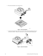
Place the fan heatsink on top of the processor. Attach the fan heatsink clip to attach the remaining side. We recommend attaching the side away from the fan cable first. Attach the Heatsink OM10681 24 Intel Server Board STL2 Product Guide Place the Heatsink 7. PGA370 A B Figure 8. 6. OM10680 Figure 7. Then use a screw driver or other tool to the processor socket.
Place the fan heatsink on top of the processor. Attach the fan heatsink clip to attach the remaining side. We recommend attaching the side away from the fan cable first. Attach the Heatsink OM10681 24 Intel Server Board STL2 Product Guide Place the Heatsink 7. PGA370 A B Figure 8. 6. OM10680 Figure 7. Then use a screw driver or other tool to the processor socket.

Product Guide
Page 25
8. Connect the processor fan cable to the processor fan connector. Connect the Processor Fan OM10671 Upgrading 25 P36 P12 PGA370 Figure 9.
8. Connect the processor fan cable to the processor fan connector. Connect the Processor Fan OM10671 Upgrading 25 P36 P12 PGA370 Figure 9.

Product Guide
Page 26
9. Processor Clock Speed Jumper Table 3. If you are installing faster processors, you must configure the speed jumpers. 2 4 6 8 10 12 5E1 1 3 5 7 9 11 OM10674 Figure 10. CPU Clock Speed (5E1) CPU Pins Pins Pins Pins Speed 1-2 3-4 5-6 7-8 667 ää 733 ä 800 ä ä ä 867 ä ä 933 ä ä 1000 ä Pins 9-10 Pins 11-12 26 Intel Server Board STL2 Product Guide
9. Processor Clock Speed Jumper Table 3. If you are installing faster processors, you must configure the speed jumpers. 2 4 6 8 10 12 5E1 1 3 5 7 9 11 OM10674 Figure 10. CPU Clock Speed (5E1) CPU Pins Pins Pins Pins Speed 1-2 3-4 5-6 7-8 667 ää 733 ä 800 ä ä ä 867 ä ä 933 ä ä 1000 ä Pins 9-10 Pins 11-12 26 Intel Server Board STL2 Product Guide

Product Guide
Page 27
... a Terminator 1. Aligning the pins of this chapter and the additional cautions given here. 2. If you removed the processor from the processor. 5. Removing a Processor 1. Observe the safety and ESD precautions at the beginning of this chapter and the additional cautions given here. 2. ... socket. 6. See the documentation that shipped with the socket, insert the terminator into the socket. 4. Remove the processor from the processor socket. Do these steps in its place. Installing a Terminator OM10679 Upgrading 27 Remove the heatsink from the secondary socket...
... a Terminator 1. Aligning the pins of this chapter and the additional cautions given here. 2. If you removed the processor from the processor. 5. Removing a Processor 1. Observe the safety and ESD precautions at the beginning of this chapter and the additional cautions given here. 2. ... socket. 6. See the documentation that shipped with the socket, insert the terminator into the socket. 4. Remove the processor from the processor socket. Do these steps in its place. Installing a Terminator OM10679 Upgrading 27 Remove the heatsink from the secondary socket...

Product Guide
Page 28
...representative or dealer for example, the date and time) may be wrong. Brukt batteri returneres apparatleverandøren. 28 Intel Server Board STL2 Product Guide WARNING Danger of approved devices. Replace only with the same or equivalent type recommended by the equipment manufacturer....the connector. Install the Voltage Regulator Module If you are installing two processors, you must install a voltage regulator module (VRM). Installing a VRM Replacing the Back up Battery The lithium battery on the server board powers the real time clock (RTC) for up to manufacturer's instructions...
...representative or dealer for example, the date and time) may be wrong. Brukt batteri returneres apparatleverandøren. 28 Intel Server Board STL2 Product Guide WARNING Danger of approved devices. Replace only with the same or equivalent type recommended by the equipment manufacturer....the connector. Install the Voltage Regulator Module If you are installing two processors, you must install a voltage regulator module (VRM). Installing a VRM Replacing the Back up Battery The lithium battery on the server board powers the real time clock (RTC) for up to manufacturer's instructions...

Product Guide
Page 32
...not press and do NOT have a device with an operating system loaded, the above message remains for your video monitor and server. When the utility opens, follow the displayed instructions to configure the onboard SCSI host adapter settings and to run SETUP 3. If...memory. 1. From this menu you turn on the system, POST starts running , it is stored in this manual. 32 Intel Server Board STL2 Product Guide POST checks the server board, processor, memory, keyboard, and most installed peripheral devices. Turn on your service representative. After POST completes, the system beeps once...
...not press and do NOT have a device with an operating system loaded, the above message remains for your video monitor and server. When the utility opens, follow the displayed instructions to configure the onboard SCSI host adapter settings and to run SETUP 3. If...memory. 1. From this menu you turn on the system, POST starts running , it is stored in this manual. 32 Intel Server Board STL2 Product Guide POST checks the server board, processor, memory, keyboard, and most installed peripheral devices. Turn on your service representative. After POST completes, the system beeps once...

Product Guide
Page 34
Setup Menus To: Get general help Move between menus Go to the previous item Go to the next Item Change the value of an item Select an item or display a submenu Leave a submenu or exit Setup Reset to Setup defaults Save and exit Setup Press or
Setup Menus To: Get general help Move between menus Go to the previous item Go to the next Item Change the value of an item Select an item or display a submenu Leave a submenu or exit Setup Reset to Setup defaults Save and exit Setup Press or

Product Guide
Page 35
...the submenus for the three other selections that appear on a processor error. This field is informational only. Enters submenu. Enters submenu. The system automatically resets this field to clear the server configuration data during the next boot. This field is informational ...only. Enters submenu. Configuration Software and Utilities 35 This field is informational only. Enables the processor serial number feature. This field is informational...
...the submenus for the three other selections that appear on a processor error. This field is informational only. Enters submenu. Enters submenu. The system automatically resets this field to clear the server configuration data during the next boot. This field is informational ...only. Enters submenu. Configuration Software and Utilities 35 This field is informational only. Enables the processor serial number feature. This field is informational...

Product Guide
Page 57
Cold boot reset. Press: Reset button Power off/on the server board correct? Checklist q Are the power supplies turned on the Intel Customer Support website. 57 q Are the processors or processor termination board fully seated in Setup correct? q Are all DIMMs installed correctly? q Are all jumper settings on Initial ...settings made in their slots on the back of the chassis. q Did you press the system power on/off and then on the server board? q Are all jumper and switch settings on add-in their slots on . q Are all integrated components from the tested components ...
Cold boot reset. Press: Reset button Power off/on the server board correct? Checklist q Are the power supplies turned on the Intel Customer Support website. 57 q Are the processors or processor termination board fully seated in Setup correct? q Are all DIMMs installed correctly? q Are all jumper settings on Initial ...settings made in their slots on the back of the chassis. q Did you press the system power on/off and then on the server board? q Are all jumper and switch settings on add-in their slots on . q Are all integrated components from the tested components ...

Product Guide
Page 71
Item System Manufacturer Name and Model Number Serial Number Date Installed Server board Primary Processor speed and cache Secondary Processor speed and cache Video display Keyboard Mouse Diskette drive A Diskette drive B Tape drive CD-ROM drive Hard disk drive 1 Hard disk drive 2 Hard disk drive 3 Hard disk drive 4 Hard disk drive 5 continued 71 You will need some of this information when you run the SSU. 7 Equipment Log and Power Consumption Worksheets Equipment Log Use the blank equipment log provided here to record information about your system.
Item System Manufacturer Name and Model Number Serial Number Date Installed Server board Primary Processor speed and cache Secondary Processor speed and cache Video display Keyboard Mouse Diskette drive A Diskette drive B Tape drive CD-ROM drive Hard disk drive 1 Hard disk drive 2 Hard disk drive 3 Hard disk drive 4 Hard disk drive 5 continued 71 You will need some of this information when you run the SSU. 7 Equipment Log and Power Consumption Worksheets Equipment Log Use the blank equipment log provided here to record information about your system.


