Product Guide
Page 9
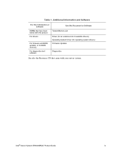
Intel® Server System SR9000MK4U Product Guide ix Table 1. Additional Information and Software For this information or software DIMMs that have been tested with this product For drivers For firmware and BIOS updates, or for BIOS recovery For diagnostics test software Use this Document or Software Tested Memory List Driver (for an extensive list of available drivers) Operating System Driver (for operating system drivers) Firmware Updates Diagnostics See also the Resource CD that came with your server system.
Intel® Server System SR9000MK4U Product Guide ix Table 1. Additional Information and Software For this information or software DIMMs that have been tested with this product For drivers For firmware and BIOS updates, or for BIOS recovery For diagnostics test software Use this Document or Software Tested Memory List Driver (for an extensive list of available drivers) Operating System Driver (for operating system drivers) Firmware Updates Diagnostics See also the Resource CD that came with your server system.

Product Guide
Page 13
... 129 Removing Chassis Handles 129 Chapter 4: Configuration Software and Utilities 131 The Extensible Firmware Interface (EFI) Boot Manager 131 The Extensible Firmware Interface (EFI) Shell 134 LSI* SAS Utility ...137 Formatting a Hard Drive 137...System Setup ...145 Starting Setup ...145 Recording Your Setup Settings 145 Navigating Setup Utility Screens 146 Primary Screens ...146 Configuring Serial-Over LAN 151 Chapter 5: Troubleshooting 153 Initial Troubleshooting Steps 153 Collecting System State Information 156 How to Read the POST Codes 159 Intel® Server System SR9000MK4U...
... 129 Removing Chassis Handles 129 Chapter 4: Configuration Software and Utilities 131 The Extensible Firmware Interface (EFI) Boot Manager 131 The Extensible Firmware Interface (EFI) Shell 134 LSI* SAS Utility ...137 Formatting a Hard Drive 137...System Setup ...145 Starting Setup ...145 Recording Your Setup Settings 145 Navigating Setup Utility Screens 146 Primary Screens ...146 Configuring Serial-Over LAN 151 Chapter 5: Troubleshooting 153 Initial Troubleshooting Steps 153 Collecting System State Information 156 How to Read the POST Codes 159 Intel® Server System SR9000MK4U...

Product Guide
Page 19
...128. Removing the Pin Shroud from the LGA Terminal 119 Figure 119. Connections Near Power Supply Box and PCI Card Divider 168 Intel® Server System SR9000MK4U Product Guide xix Figure 90. Checking the Backplane Cover Latches 89 Figure 91. Removing the Air Flow Guide 96 Figure 96. ...Attaching the Hard Drive Backplane to the Heat Sink 116 Figure 114. Firmware Update Block Diagram 141 Figure 132. Lifting the Fan Box from the Processor 123 Figure 125. Securing the Processor to the System 108 Figure 106. Installing the LGA Terminal Cover 122 Figure 123. ...
...128. Removing the Pin Shroud from the LGA Terminal 119 Figure 119. Connections Near Power Supply Box and PCI Card Divider 168 Intel® Server System SR9000MK4U Product Guide xix Figure 90. Checking the Backplane Cover Latches 89 Figure 91. Removing the Air Flow Guide 96 Figure 96. ...Attaching the Hard Drive Backplane to the Heat Sink 116 Figure 114. Firmware Update Block Diagram 141 Figure 132. Lifting the Fan Box from the Processor 123 Figure 125. Securing the Processor to the System 108 Figure 106. Installing the LGA Terminal Cover 122 Figure 123. ...

Product Guide
Page 153
...the Boot Maintenance Menu options. • Boot Maintenance: A menu of the EFI shell, see "The Extensible Firmware Interface (EFI) Shell" on page 132 describes each menu item in the server, or the boot maintenance menu. • EFI Shell: A simple and interactive environment that are used to ... Maintenance Menu, the user can load the EFI device drivers, start the EFI applications, and boot the operating systems. The EFI shell also provides a series of server. Each boot option specifies an EFI executable with various ways according to control the booting environment of commands that...
...the Boot Maintenance Menu options. • Boot Maintenance: A menu of the EFI shell, see "The Extensible Firmware Interface (EFI) Shell" on page 132 describes each menu item in the server, or the boot maintenance menu. • EFI Shell: A simple and interactive environment that are used to ... Maintenance Menu, the user can load the EFI device drivers, start the EFI applications, and boot the operating systems. The EFI shell also provides a series of server. Each boot option specifies an EFI executable with various ways according to control the booting environment of commands that...
Product Guide
Page 156
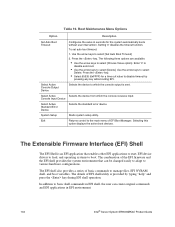
...Output Device Selects the device to various hardware configurations. The Extensible Firmware Interface (EFI) Shell The EFI Shell is sent. Press the key. • Select 65535 (0xFFFF) for the system automatically boots without user intervention. The following three options are ...key while booting EFI. System Setup Starts system setup utility. Setting '0' disables the timeout function. Boot Maintenance Menu Options Option Description Set Auto Boot Timeout Configures the value in EFI environment. 134 Intel® Server System SR9000MK4U Product Guide Console Input Device...
...Output Device Selects the device to various hardware configurations. The Extensible Firmware Interface (EFI) Shell The EFI Shell is sent. Press the key. • Select 65535 (0xFFFF) for the system automatically boots without user intervention. The following three options are ...key while booting EFI. System Setup Starts system setup utility. Setting '0' disables the timeout function. Boot Maintenance Menu Options Option Description Set Auto Boot Timeout Configures the value in EFI environment. 134 Intel® Server System SR9000MK4U Product Guide Console Input Device...

Product Guide
Page 159
... PCI Address (Bus/Dev/Func) MPT Firmware Revision SAS Address Status Boot Support SAS Topology SAS1068 09:01:00 0.07.07.00-IT 500605B0:00016CA0 Enabled [Enabled BIOS & OS] Advanced Adapter Properties Esc = Exit Menu Enter = Select Item F1/Shift+1 = Help -/+ = Change Item Intel® Server System SR9000MK4U Product Guide 137 Boot to format your...
... PCI Address (Bus/Dev/Func) MPT Firmware Revision SAS Address Status Boot Support SAS Topology SAS1068 09:01:00 0.07.07.00-IT 500605B0:00016CA0 Enabled [Enabled BIOS & OS] Advanced Adapter Properties Esc = Exit Menu Enter = Select Item F1/Shift+1 = Help -/+ = Change Item Intel® Server System SR9000MK4U Product Guide 137 Boot to format your...

Product Guide
Page 162
.... A FWUPDATE is performed as an EFI shell command. 140 Intel® Server System SR9000MK4U Product Guide 8. Clearing the CMOS To clear the CMOS, use the following screen. Turn off the system. 2. Upgrading the Firmware The FWUPDATE utility updates the SAL/BMC and writes sensor data records... restart. Exit the Configuration Utility and Restart Esc = Exit Menu F1/Shift+1 = Help 9. Power on the system. Hold down the reset button until you want to the Intel® Server System SR9000MK4U. Select Exit the Configuration Utility and Restart and press the key to flash. 4.
.... A FWUPDATE is performed as an EFI shell command. 140 Intel® Server System SR9000MK4U Product Guide 8. Clearing the CMOS To clear the CMOS, use the following screen. Turn off the system. 2. Upgrading the Firmware The FWUPDATE utility updates the SAL/BMC and writes sensor data records... restart. Exit the Configuration Utility and Restart Esc = Exit Menu F1/Shift+1 = Help 9. Power on the system. Hold down the reset button until you want to the Intel® Server System SR9000MK4U. Select Exit the Configuration Utility and Restart and press the key to flash. 4.

Product Guide
Page 163
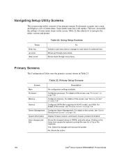
Firmware Update Block Diagram Intel® Server System SR9000MK4U Product Guide 141 SAL Spool BMC external flash AF001197 Figure 131. Software EFI Hardware Removable media Fwupdate.efi SAL code BMC code SDR data ESB2 Removable device Integrated ROM file (The file that integrates the update ROM data.) LPC Bus SMBus FWH SAL 8MB Share Bus BMC Flash ROM BMC 512KB FPGA BMC internal flash Flash ROM#1 SAL 8MB Flash ROM#0 BMC 512KB Copied to internal flash by BMC reset sequence.
Firmware Update Block Diagram Intel® Server System SR9000MK4U Product Guide 141 SAL Spool BMC external flash AF001197 Figure 131. Software EFI Hardware Removable media Fwupdate.efi SAL code BMC code SDR data ESB2 Removable device Integrated ROM file (The file that integrates the update ROM data.) LPC Bus SMBus FWH SAL 8MB Share Bus BMC Flash ROM BMC 512KB FPGA BMC internal flash Flash ROM#1 SAL 8MB Flash ROM#0 BMC 512KB Copied to internal flash by BMC reset sequence.

Product Guide
Page 164
...by SAL is unmatched between FWH SAL and integrated ROM SAL, the takeover is recovered from SAL Spool by using the SAL firmware recovery function. • Takeover of the FWUPDATE process. Use ROM image data IA64_640.ROM in the integrated ROM file is unmatched to ....ROM; fwupdate fs0:IA64_640.ROM; (not recommend) Command works if fs0 is the current drive Figure 132. FWUPDATE File Path Example 142 Intel® Server System SR9000MK4U Product Guide Use ROM image data IA64_640.ROM in fs0 root directory. fwupdate fs0:\work directory under current dir. fwupdate work directory. Use ...
...by SAL is unmatched between FWH SAL and integrated ROM SAL, the takeover is recovered from SAL Spool by using the SAL firmware recovery function. • Takeover of the FWUPDATE process. Use ROM image data IA64_640.ROM in the integrated ROM file is unmatched to ....ROM; fwupdate fs0:IA64_640.ROM; (not recommend) Command works if fs0 is the current drive Figure 132. FWUPDATE File Path Example 142 Intel® Server System SR9000MK4U Product Guide Use ROM image data IA64_640.ROM in fs0 root directory. fwupdate fs0:\work directory under current dir. fwupdate work directory. Use ...

Product Guide
Page 166
... update process start *** Erasing FLASH Devices 100% Done! Add SDR 100% Done! ****** Firmware Version Display ****** Now BMC 01-03 SAL 01-02 Firmware update process was completed. Figure 133. Sumcheck BMC Data Done! ****** Firmware Version Display ****** Current - Programming FLASH Devices 100% Done Verifying FLASH 100% Done! ***... Sumcheck SAL Data Done! Verifying FLASH 100% Done! ****** SDR update process start *** Erasing FLASH Devices 100% Done! Restart this system at once. FWUPDATE Execution Screen 144 Intel® Server System SR9000MK4U Product Guide
... update process start *** Erasing FLASH Devices 100% Done! Add SDR 100% Done! ****** Firmware Version Display ****** Now BMC 01-03 SAL 01-02 Firmware update process was completed. Figure 133. Sumcheck BMC Data Done! ****** Firmware Version Display ****** Current - Programming FLASH Devices 100% Done Verifying FLASH 100% Done! ***... Sumcheck SAL Data Done! Verifying FLASH 100% Done! ****** SDR update process start *** Erasing FLASH Devices 100% Done! Restart this system at once. FWUPDATE Execution Screen 144 Intel® Server System SR9000MK4U Product Guide
Product Guide
Page 168
... in Table 23. Clicking on the menu item causes the system to navigate the utility screens and menus. Yes: Saves the changes and reboots the system. No: Aborts the action. 146 Intel® Server System SR9000MK4U Product Guide The user can modify the settings of menu items.... Some menu items have sub-menus. Moves up arrow down through menu items. Moves down arrow Table 22. Configures processor. For details of this screen, see "Devices Screen" on page 149. Display firmware...
... in Table 23. Clicking on the menu item causes the system to navigate the utility screens and menus. Yes: Saves the changes and reboots the system. No: Aborts the action. 146 Intel® Server System SR9000MK4U Product Guide The user can modify the settings of menu items.... Some menu items have sub-menus. Moves up arrow down through menu items. Moves down arrow Table 22. Configures processor. For details of this screen, see "Devices Screen" on page 149. Display firmware...

Product Guide
Page 172
... Screen Table 28 describes the menu items available on the Server Management screen. Description Pressing invokes the submenu to COM1. Default gateway address of management LAN port. No: Aborts the action. Disable: Does not output firmware or EFI console input/output to OS. Does not provide ...SPCR or HCDP to COM1. Pressing prompts the user to OS. Available when DHCP is valid. 150 Intel® Server System SR9000MK4U Product Guide Provides SPCR or HCDP to respond Yes ...
... Screen Table 28 describes the menu items available on the Server Management screen. Description Pressing invokes the submenu to COM1. Default gateway address of management LAN port. No: Aborts the action. Disable: Does not output firmware or EFI console input/output to OS. Does not provide ...SPCR or HCDP to COM1. Pressing prompts the user to OS. Available when DHCP is valid. 150 Intel® Server System SR9000MK4U Product Guide Provides SPCR or HCDP to respond Yes ...
Product Guide
Page 173
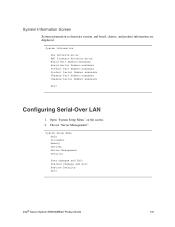
... Save changes and Exit Discard changes and Exit Restore Defaults Exit Intel® Server System SR9000MK4U Product Guide 151 System Information Screen System information as firmware version, and board, chassis, and product information are displayed. Open "System Setup Menu" on the screen. 2. System Information SAL Revision:xx-xx BMC Firmware Revision:xx-xx Board Part Number:xxxxxxxx Board Serial Number...
... Save changes and Exit Discard changes and Exit Restore Defaults Exit Intel® Server System SR9000MK4U Product Guide 151 System Information Screen System information as firmware version, and board, chassis, and product information are displayed. Open "System Setup Menu" on the screen. 2. System Information SAL Revision:xx-xx BMC Firmware Revision:xx-xx Board Part Number:xxxxxxxx Board Serial Number...
Product Guide
Page 185
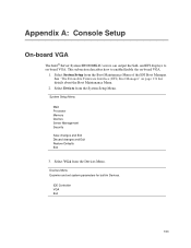
... This subsection describes how to on-board VGA. Select VGA from the System Setup Menu. Devices Menu Examine and set system parameters for details about the Boot Maintenance Menu. 2. See "The Extensible Firmware Interface (EFI) Boot Manager" on page 131 for built-in Devices....Maintenance Menu of the EFI Boot Manager. System Setup Menu Main Processor Memory Devices Server Management Security Save changes and Exit Discard changes and Exit Restore Defaults Exit 3. Appendix A: Console Setup On-board VGA The Intel® Server System SR9000MK4U server can output the SAL and EFI displays ...
... This subsection describes how to on-board VGA. Select VGA from the System Setup Menu. Devices Menu Examine and set system parameters for details about the Boot Maintenance Menu. 2. See "The Extensible Firmware Interface (EFI) Boot Manager" on page 131 for built-in Devices....Maintenance Menu of the EFI Boot Manager. System Setup Menu Main Processor Memory Devices Server Management Security Save changes and Exit Discard changes and Exit Restore Defaults Exit 3. Appendix A: Console Setup On-board VGA The Intel® Server System SR9000MK4U server can output the SAL and EFI displays ...
Product Guide
Page 187
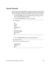
... and EFI to set server management parameters. Select Server Management from the System Setup Menu. Console Redirection Management LAN SEL Clear Exit Intel® Server System SR9000MK4U Product Guide 165 System Setup Menu Main Processor Memory Devices Server Management Security Save changes and Exit Discard changes and Exit Restore Defaults Exit 3. Serial Console The Intel® Server System SR9000MK4U server supports headless function that...
... and EFI to set server management parameters. Select Server Management from the System Setup Menu. Console Redirection Management LAN SEL Clear Exit Intel® Server System SR9000MK4U Product Guide 165 System Setup Menu Main Processor Memory Devices Server Management Security Save changes and Exit Discard changes and Exit Restore Defaults Exit 3. Serial Console The Intel® Server System SR9000MK4U server supports headless function that...
