Product Guide
Page 7
... installing or replacing components such as the hard drives, memory, processor, fans, boards and other components. Chapter 5 provides instructions on how to update the system. Preface About this Manual Thank you for adding and replacing components. This manual is written for performing troubleshooting activities to identify the source of the server system utilities, and instructions on using Intel® server products. Manual Organization Chapter 1 provides a brief overview of the product, and product diagrams to install the system...
... installing or replacing components such as the hard drives, memory, processor, fans, boards and other components. Chapter 5 provides instructions on how to update the system. Preface About this Manual Thank you for adding and replacing components. This manual is written for performing troubleshooting activities to identify the source of the server system utilities, and instructions on using Intel® server products. Manual Organization Chapter 1 provides a brief overview of the product, and product diagrams to install the system...
Product Guide
Page 8
..., hard drive, USB floppy drive, CD-ROM or DVD-ROM drive, RAID controller, operating system. Additional Information and Software For this product and need more of the screen and select the option to install it Accessories or other Intel server products Hardware (peripheral boards, adapter cards) and operating systems that have been tested with this product Processors that can be used with this server board, use the following accessory items for your board, and for ordering information for Intel products, see http://support.intel.com/support/motherboards/server/SR9000MK4U...
..., hard drive, USB floppy drive, CD-ROM or DVD-ROM drive, RAID controller, operating system. Additional Information and Software For this product and need more of the screen and select the option to install it Accessories or other Intel server products Hardware (peripheral boards, adapter cards) and operating systems that have been tested with this product Processors that can be used with this server board, use the following accessory items for your board, and for ordering information for Intel products, see http://support.intel.com/support/motherboards/server/SR9000MK4U...
Product Guide
Page 9
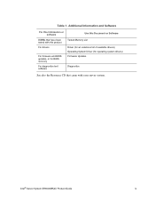
Additional Information and Software For this information or software DIMMs that have been tested with this product For drivers For firmware and BIOS updates, or for BIOS recovery For diagnostics test software Use this Document or Software Tested Memory List Driver (for an extensive list of available drivers) Operating System Driver (for operating system drivers) Firmware Updates Diagnostics See also the Resource CD that came with your server system. Intel® Server System SR9000MK4U Product Guide ix Table 1.
Additional Information and Software For this information or software DIMMs that have been tested with this product For drivers For firmware and BIOS updates, or for BIOS recovery For diagnostics test software Use this Document or Software Tested Memory List Driver (for an extensive list of available drivers) Operating System Driver (for operating system drivers) Firmware Updates Diagnostics See also the Resource CD that came with your server system. Intel® Server System SR9000MK4U Product Guide ix Table 1.

Product Guide
Page 11
... Rear ...9 Internal Layout ...11 Internal Chassis Features ...12 Power Supply Subsystem 12 Cooling Subsystem ...14 PCI Card Slot ...15 Chapter 2: Intel® Server System SR9000MK4U Board Set Overview 17 Main Board ...18 Configuration Restrictions 22 Processor Configurations 23 Memory Box Card ...24 DIMM Configurations 25 Hard Drive Backplane ...29 Hard Drive Population 30 Front Panel Board ...30 Chapter 3: Installing and Removing Components 33 Tools Needed ...33 Installing and Removing the Front Bezel 34 Removing the Front Bezel 34 Intel® Server System SR9000MK4U Product Guide...
... Rear ...9 Internal Layout ...11 Internal Chassis Features ...12 Power Supply Subsystem 12 Cooling Subsystem ...14 PCI Card Slot ...15 Chapter 2: Intel® Server System SR9000MK4U Board Set Overview 17 Main Board ...18 Configuration Restrictions 22 Processor Configurations 23 Memory Box Card ...24 DIMM Configurations 25 Hard Drive Backplane ...29 Hard Drive Population 30 Front Panel Board ...30 Chapter 3: Installing and Removing Components 33 Tools Needed ...33 Installing and Removing the Front Bezel 34 Removing the Front Bezel 34 Intel® Server System SR9000MK4U Product Guide...

Product Guide
Page 12
... Panel and Optical Drive Assembly 74 Installing the Front Control Panel and Optical Drive Assembly 75 Installing and Removing the Power Supply Box 76 Removing the Power Supply Box 76 Installing the Power Supply Box 80 Installing and Removing the Power Supply Support 83 Removing the Power Supply Support 83 Installing the Power Supply Support 85 Installing and Removing the Hard Drive Backplane Cover 87 Removing the Hard Drive Backplane Cover 87 Installing the Hard Drive Backplane Cover 88 Installing and Removing the KVM Card 89 xii Intel® Server System SR9000MK4U Product Guide
... Panel and Optical Drive Assembly 74 Installing the Front Control Panel and Optical Drive Assembly 75 Installing and Removing the Power Supply Box 76 Removing the Power Supply Box 76 Installing the Power Supply Box 80 Installing and Removing the Power Supply Support 83 Removing the Power Supply Support 83 Installing the Power Supply Support 85 Installing and Removing the Hard Drive Backplane Cover 87 Removing the Hard Drive Backplane Cover 87 Installing the Hard Drive Backplane Cover 88 Installing and Removing the KVM Card 89 xii Intel® Server System SR9000MK4U Product Guide

Product Guide
Page 13
...) Boot Manager 131 The Extensible Firmware Interface (EFI) Shell 134 LSI* SAS Utility ...137 Formatting a Hard Drive 137 Clearing the CMOS ...140 Upgrading the Firmware ...140 How to Use FWUPDATE 142 Execution Screen ...144 Using System Setup ...145 Starting Setup ...145 Recording Your Setup Settings 145 Navigating Setup Utility Screens 146 Primary Screens ...146 Configuring Serial-Over LAN 151 Chapter 5: Troubleshooting 153 Initial Troubleshooting Steps 153 Collecting System State Information 156 How to Read the POST Codes 159 Intel® Server System SR9000MK4U Product Guide...
...) Boot Manager 131 The Extensible Firmware Interface (EFI) Shell 134 LSI* SAS Utility ...137 Formatting a Hard Drive 137 Clearing the CMOS ...140 Upgrading the Firmware ...140 How to Use FWUPDATE 142 Execution Screen ...144 Using System Setup ...145 Starting Setup ...145 Recording Your Setup Settings 145 Navigating Setup Utility Screens 146 Primary Screens ...146 Configuring Serial-Over LAN 151 Chapter 5: Troubleshooting 153 Initial Troubleshooting Steps 153 Collecting System State Information 156 How to Read the POST Codes 159 Intel® Server System SR9000MK4U Product Guide...

Product Guide
Page 17
... 7. Front Panel Board Layout 30 Figure 21. Installing the Top Cover 37 Figure 25. Memory Box Front View 46 Figure 36. Optical Drive Bracket with Drive Installed 6 Figure 5. Open System, Top View 11 Figure 9. Memory Upgrade Path 28 Figure 18. Hard Drive Backplane Bottom View 29 Figure 20. Removing the Top Cover 36 Figure 24. Locating the Optical Drive Installation Position 53 Intel® Server System SR9000MK4U Product Guide xvii Power Supply Indicators 13 Figure 10. Cooling Fan Indicator 14...
... 7. Front Panel Board Layout 30 Figure 21. Installing the Top Cover 37 Figure 25. Memory Box Front View 46 Figure 36. Optical Drive Bracket with Drive Installed 6 Figure 5. Open System, Top View 11 Figure 9. Memory Upgrade Path 28 Figure 18. Hard Drive Backplane Bottom View 29 Figure 20. Removing the Top Cover 36 Figure 24. Locating the Optical Drive Installation Position 53 Intel® Server System SR9000MK4U Product Guide xvii Power Supply Indicators 13 Figure 10. Cooling Fan Indicator 14...

Product Guide
Page 18
.... Locating the Lens Switch and PCI Card LED 67 Figure 64. Removing a Power Supply Filler 69 Figure 65. Installing a Power Supply 69 Figure 66. Connecting the IDE and SATA Cables 82 Figure 84. Removing a Fan ...57 Figure 49. Closing the PCI Caution Plate 66 Figure 63. Locating the Fans 57 Figure 48. Removing Optical Drive from the Tail Lock 64 Figure 60. Locking the Power Supply into Place 65 Figure 62. Locking a PCI Card or Slot Cover into...
.... Locating the Lens Switch and PCI Card LED 67 Figure 64. Removing a Power Supply Filler 69 Figure 65. Installing a Power Supply 69 Figure 66. Connecting the IDE and SATA Cables 82 Figure 84. Removing a Fan ...57 Figure 49. Closing the PCI Caution Plate 66 Figure 63. Locating the Fans 57 Figure 48. Removing Optical Drive from the Tail Lock 64 Figure 60. Locking the Power Supply into Place 65 Figure 62. Locking a PCI Card or Slot Cover into...

Product Guide
Page 19
... Hard Drive Backplane 107 Figure 105. Setting the MVR into Place 127 Figure 130. Lifting the Mounting Plate from System 106 Figure 104. Setting the Mounting Plate into Place on the Processor Assembly 119 Figure 120. FWUPDATE File Path Example 142 Figure 133. Connections Near Power Supply Box and PCI Card Divider 168 Intel® Server System SR9000MK4U Product Guide xix Installing the PCI Divider 93 Figure 94. Removing...
... Hard Drive Backplane 107 Figure 105. Setting the MVR into Place 127 Figure 130. Lifting the Mounting Plate from System 106 Figure 104. Setting the Mounting Plate into Place on the Processor Assembly 119 Figure 120. FWUPDATE File Path Example 142 Figure 133. Connections Near Power Supply Box and PCI Card Divider 168 Intel® Server System SR9000MK4U Product Guide xix Installing the PCI Divider 93 Figure 94. Removing...

Product Guide
Page 25
Hot-swap hard drive bay: hard drive LEDs - PCI slots - PCI hot plug Intel® Server System SR9000MK4U Product Guide 3 Power supplies and AC inputs - Identification switch • Chassis top - Cooling fan - Memory box: Memory box serviceability LEDs • Chassis rear - IO ports - Front panel: Front panel switches and LEDs - External Chassis Features System control buttons and indicators are located in several places on the chassis: • Chassis front - Optical drive bay - Power supply indicators -
Hot-swap hard drive bay: hard drive LEDs - PCI slots - PCI hot plug Intel® Server System SR9000MK4U Product Guide 3 Power supplies and AC inputs - Identification switch • Chassis top - Cooling fan - Memory box: Memory box serviceability LEDs • Chassis rear - IO ports - Front panel: Front panel switches and LEDs - External Chassis Features System control buttons and indicators are located in several places on the chassis: • Chassis front - Optical drive bay - Power supply indicators -

Product Guide
Page 29
... hard drive types in Table 4. Intel® Server System SR9000MK4U Product Guide 7 The hard drive carriers contain light-pipes that allow dual-color LED indicators to change. See the Intel® Server System SR9000MK4U Tested Hardware and Operating System List for the LED status to display through the bezel. The hard drive status is described in the Server System SR9000MK4U. SAS Hard Drive LED Details State On 4 Hz blink 1 Hz blink On Blink Description Activity Locate Rebuild Error Hard drive insert Power on the system. - Watch for a list of the drives supported. LED...
... hard drive types in Table 4. Intel® Server System SR9000MK4U Product Guide 7 The hard drive carriers contain light-pipes that allow dual-color LED indicators to change. See the Intel® Server System SR9000MK4U Tested Hardware and Operating System List for the LED status to display through the bezel. The hard drive status is described in the Server System SR9000MK4U. SAS Hard Drive LED Details State On 4 Hz blink 1 Hz blink On Blink Description Activity Locate Rebuild Error Hard drive insert Power on the system. - Watch for a list of the drives supported. LED...

Product Guide
Page 31
... . Bottom right: RUSB0 Standard VGA compatible, 15-pin connector 9-pin RS-232 connector Toggles chassis ID LED on the rear panel. Chassis Rear View Intel® Server System SR9000MK4U Product Guide 9 Slot 1: PCI-Express x 8, half length RJ45 connectors. Management LAN port - A B A AC input power connectors B AC input power connectors C PCI Slots D Dual Gb Ethernet ports E 100 Mb Ethernet ports F Four USB ports G Video port H Serial port I Identification Button D F H C E G I AF001087 All slots support hot-plug PCI add-in cards. Ether0: left : RUSB3...
... . Bottom right: RUSB0 Standard VGA compatible, 15-pin connector 9-pin RS-232 connector Toggles chassis ID LED on the rear panel. Chassis Rear View Intel® Server System SR9000MK4U Product Guide 9 Slot 1: PCI-Express x 8, half length RJ45 connectors. Management LAN port - A B A AC input power connectors B AC input power connectors C PCI Slots D Dual Gb Ethernet ports E 100 Mb Ethernet ports F Four USB ports G Video port H Serial port I Identification Button D F H C E G I AF001087 All slots support hot-plug PCI add-in cards. Ether0: left : RUSB3...

Product Guide
Page 48
... the same data is half that of Mirror Mode Disabled or Enabled Disabled Enabled Redundancy and Hotswap Support No No Yes The following table for each other and provide redundancy. Memory Operational Modes Memory Operational Mode Single Double Mirror Description One MMR is applicable. No redundancy. Number of MMR Connected to One NDC 1 2 2 BIOS Set-Up of Double mode. The paths to the right of figures (1-A, 2-A, 3-A, 4-A) represent...
... the same data is half that of Mirror Mode Disabled or Enabled Disabled Enabled Redundancy and Hotswap Support No No Yes The following table for each other and provide redundancy. Memory Operational Modes Memory Operational Mode Single Double Mirror Description One MMR is applicable. No redundancy. Number of MMR Connected to One NDC 1 2 2 BIOS Set-Up of Double mode. The paths to the right of figures (1-A, 2-A, 3-A, 4-A) represent...
Product Guide
Page 55
... example, to remove the PCI card divider, you first need to first install or remove other components. This means you may result from one procedure to the next. This guide will need to remove the chassis cover, the power supplies, the power supply box, the CPU1/CPU2 MVR cable, the KVM card, and all add-in cards. 3 Installing and Removing Components To complete many of the safety instructions located in "Safety Information...
... example, to remove the PCI card divider, you first need to first install or remove other components. This means you may result from one procedure to the next. This guide will need to remove the chassis cover, the power supplies, the power supply box, the CPU1/CPU2 MVR cable, the KVM card, and all add-in cards. 3 Installing and Removing Components To complete many of the safety instructions located in "Safety Information...

Product Guide
Page 99
.... Remove the cables from the main board. Disconnect the IDE cable from the main board. Disconnect the CPU1 / CPU2 MVR cable from the main board. AF001431 Figure 73. Disconnecting the IDE and SATA Cables Intel® Server System SR9000MK4U Product Guide 77 To disconnect this cable, press and hold the latch on the cable connector while pulling on the connector. See the figure below . 3. Locating the CPU1 / CPU2 MVR Connection...
.... Remove the cables from the main board. Disconnect the IDE cable from the main board. Disconnect the CPU1 / CPU2 MVR cable from the main board. AF001431 Figure 73. Disconnecting the IDE and SATA Cables Intel® Server System SR9000MK4U Product Guide 77 To disconnect this cable, press and hold the latch on the cable connector while pulling on the connector. See the figure below . 3. Locating the CPU1 / CPU2 MVR Connection...
Product Guide
Page 107
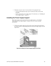
... next course of another procedure, return to the appropriate steps: - Setting the Power Supply Support into place in the system, lining up the guide pins in the chassis with the corresponding guide holes in "Removing the Power Supply Support" on page 85. If you have removed the power supply support, as part of action and refer to that procedure. - Determine your system is partially disassembled. 1. See the figure below. Install a replacement power supply support. 3.
... next course of another procedure, return to the appropriate steps: - Setting the Power Supply Support into place in the system, lining up the guide pins in the chassis with the corresponding guide holes in "Removing the Power Supply Support" on page 85. If you have removed the power supply support, as part of action and refer to that procedure. - Determine your system is partially disassembled. 1. See the figure below. Install a replacement power supply support. 3.

Product Guide
Page 154
... are added if these devices exist. Type the name of all EFI System Partitions in the root directories of the EFI application to boot with the name, either ASCII or UNICODE arguments that is found, it as a boot option automatically. The user specifies the option by providing the EFI application name. Press the key. 5. Use the arrow keys to the Boot Manager. 132 Intel® Server System SR9000MK4U Product Guide...
... are added if these devices exist. Type the name of all EFI System Partitions in the root directories of the EFI application to boot with the name, either ASCII or UNICODE arguments that is found, it as a boot option automatically. The user specifies the option by providing the EFI application name. Press the key. 5. Use the arrow keys to the Boot Manager. 132 Intel® Server System SR9000MK4U Product Guide...
Product Guide
Page 156
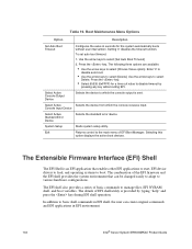
... device to boot. Use the arrow keys to select [Choose Value option]. System Setup Starts system setup utility. Boot Maintenance Menu Options Option Description Set Auto Boot Timeout Configures the value in EFI environment. 134 Intel® Server System SR9000MK4U Product Guide The combination of EFI shell utility is an EFI application that can create original commands and EFI applications in seconds for a time out value to various hardware configurations. Press the key. The EFI shell also provides a series...
... device to boot. Use the arrow keys to select [Choose Value option]. System Setup Starts system setup utility. Boot Maintenance Menu Options Option Description Set Auto Boot Timeout Configures the value in EFI environment. 134 Intel® Server System SR9000MK4U Product Guide The combination of EFI shell utility is an EFI application that can create original commands and EFI applications in seconds for a time out value to various hardware configurations. Press the key. The EFI shell also provides a series...
Product Guide
Page 167
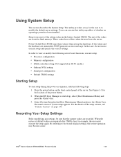
... [Boot Maintenance Menu] and press the key. 3. For the details of system setup appears. When the restore of the values are unmatched, POST generates an error message. Intel® Server System SR9000MK4U Product Guide 145 Recording Your Setup Settings Before modifying any settings, be sure that case, the user must execute the setup again. Select [System Setup] in 4S-4U model.) • Onboard VGA setting • Serial port configuration • Default CMOS settings Starting Setup To start setup during the power-on the front control panel of...
... [Boot Maintenance Menu] and press the key. 3. For the details of system setup appears. When the restore of the values are unmatched, POST generates an error message. Intel® Server System SR9000MK4U Product Guide 145 Recording Your Setup Settings Before modifying any settings, be sure that case, the user must execute the setup again. Select [System Setup] in 4S-4U model.) • Onboard VGA setting • Serial port configuration • Default CMOS settings Starting Setup To start setup during the power-on the front control panel of...

Product Guide
Page 177
... system are properly connected. The rear ports are properly connected. Check that the hard drive is installed into the slot properly. Check that the MVR power cable is used in mirror mode (green memory box mirror LED is configured. Memory capacity is configured. Replace the DVD-ROM drive. Attention LED (yellow) blinks. Check that the SAS/SATA cable, etc. Check that the processor is indicated less than actual loaded capacity. Check if memory is properly connected. Check that the network cable...
... system are properly connected. The rear ports are properly connected. Check that the hard drive is installed into the slot properly. Check that the MVR power cable is used in mirror mode (green memory box mirror LED is configured. Memory capacity is configured. Replace the DVD-ROM drive. Attention LED (yellow) blinks. Check that the SAS/SATA cable, etc. Check that the processor is indicated less than actual loaded capacity. Check if memory is properly connected. Check that the network cable...


