Product Guide
Page 2
... estoppel or otherwise, to specifications and product descriptions at any patent, copyright or other countries. * Other names and brands may occur. All Rights Reserved ii Intel® Server System SR9000MK4U Product Guide Intel Corporation can not be claimed as provided in the United States and other intellectual property right. Except as the property of the...
... estoppel or otherwise, to specifications and product descriptions at any patent, copyright or other countries. * Other names and brands may occur. All Rights Reserved ii Intel® Server System SR9000MK4U Product Guide Intel Corporation can not be claimed as provided in the United States and other intellectual property right. Except as the property of the...

Product Guide
Page 3
...any of the instructions. Consultez Intel Server Boards and Server Chassis Safety Information sur le Resource CD ou bien rendez-vous sur le site http:// support.intel.com/support/motherboards/server/sb/cs-010770.htm. See also Intel Server Boards and Server Chassis Safety Information on the ...Resource CD and/or at http://support.intel.com/support/motherboards/server/sb/cs010770.htm. Instrucciones de seguridad importantes...
...any of the instructions. Consultez Intel Server Boards and Server Chassis Safety Information sur le Resource CD ou bien rendez-vous sur le site http:// support.intel.com/support/motherboards/server/sb/cs-010770.htm. See also Intel Server Boards and Server Chassis Safety Information on the ...Resource CD and/or at http://support.intel.com/support/motherboards/server/sb/cs010770.htm. Instrucciones de seguridad importantes...

Product Guide
Page 4
... product is unplugged before opening it. To remove power from system, you open the chassis, add, or remove any unpainted metal surface on power, telephone, and communication cables. iv Intel® Server System SR9000MK4U Product Guide Make sure the AC power cord is sold. ...Otherwise, personal injury or equipment damage can be present on your server product, whether you perform all procedures in this guide. ...
... product is unplugged before opening it. To remove power from system, you open the chassis, add, or remove any unpainted metal surface on power, telephone, and communication cables. iv Intel® Server System SR9000MK4U Product Guide Make sure the AC power cord is sold. ...Otherwise, personal injury or equipment damage can be present on your server product, whether you perform all procedures in this guide. ...

Product Guide
Page 5
... using needle nosed pliers to grip with a pair of the jumper with the function controlled by that jumper. Take care to remove or install a jumper; Intel® Server System SR9000MK4U Product Guide v grip the narrow sides of fine needle nosed pliers. Installing or removing jumpers: A jumper is a small plastic encased conductor that you can...
... using needle nosed pliers to grip with a pair of the jumper with the function controlled by that jumper. Take care to remove or install a jumper; Intel® Server System SR9000MK4U Product Guide v grip the narrow sides of fine needle nosed pliers. Installing or removing jumpers: A jumper is a small plastic encased conductor that you can...
Product Guide
Page 7
..., boards and other components. In this chapter, you will find a list of the server board features, photos of a problem. Preface About this Manual Thank you for troubleshooting, upgrading, and managing the Intel® Server System SR9000MK4U. This manual is written for system technicians who are responsible for purchasing and using the utilities that are shipped with...
..., boards and other components. In this chapter, you will find a list of the server board features, photos of a problem. Preface About this Manual Thank you for troubleshooting, upgrading, and managing the Intel® Server System SR9000MK4U. This manual is written for system technicians who are responsible for purchasing and using the utilities that are shipped with...
Product Guide
Page 8
... Processors that can be used with this product Use this Document or Software Intel® Server System SR9000MK4U Technical Product Specification Intel® Server System SR9000MK4U Quick Start User's Guide in the product box Spares and Configuration Guide Tested Hardware Operating Systems List Supported Processors viii Intel® Server System SR9000MK4U Product Guide Table 1. For information about this product and need more of...
... Processors that can be used with this product Use this Document or Software Intel® Server System SR9000MK4U Technical Product Specification Intel® Server System SR9000MK4U Quick Start User's Guide in the product box Spares and Configuration Guide Tested Hardware Operating Systems List Supported Processors viii Intel® Server System SR9000MK4U Product Guide Table 1. For information about this product and need more of...
Product Guide
Page 9
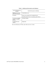
Table 1. Intel® Server System SR9000MK4U Product Guide ix Additional Information and Software For this information or software DIMMs that have been tested with this product For drivers For firmware and BIOS updates, or for BIOS recovery For diagnostics test software Use this Document or Software Tested Memory List Driver (for an extensive list of available drivers) Operating System Driver (for operating system drivers) Firmware Updates Diagnostics See also the Resource CD that came with your server system.
Table 1. Intel® Server System SR9000MK4U Product Guide ix Additional Information and Software For this information or software DIMMs that have been tested with this product For drivers For firmware and BIOS updates, or for BIOS recovery For diagnostics test software Use this Document or Software Tested Memory List Driver (for an extensive list of available drivers) Operating System Driver (for operating system drivers) Firmware Updates Diagnostics See also the Resource CD that came with your server system.

Product Guide
Page 10
... the power cables to AC input power connectors in the back of the system and to power the system back on the front panel for any signs of this manual for information. 2. x Intel® Server System SR9000MK4U Product Guide If peripheral devices are attached that need to be connected. ...2. If the power is used, both power supplies must be used only if the system has locked up. See your peripheral guides for help...
... the power cables to AC input power connectors in the back of the system and to power the system back on the front panel for any signs of this manual for information. 2. x Intel® Server System SR9000MK4U Product Guide If peripheral devices are attached that need to be connected. ...2. If the power is used, both power supplies must be used only if the system has locked up. See your peripheral guides for help...

Product Guide
Page 11
...Organization ...vii Product Accessories ...viii Additional Information and Software viii Powering the System On and Off x Powering On the System Power x Powering Off the System Power x Chapter 1: Intel® Server System SR9000MK4U Chassis Overview 1 Chassis Description ...2 External Chassis Features ...3 Chassis Front ...Internal Chassis Features ...12 Power Supply Subsystem 12 Cooling Subsystem ...14 PCI Card Slot ...15 Chapter 2: Intel® Server System SR9000MK4U Board Set Overview 17 Main Board ...18 Configuration Restrictions 22 Processor Configurations 23 Memory Box Card ...24 ...
...Organization ...vii Product Accessories ...viii Additional Information and Software viii Powering the System On and Off x Powering On the System Power x Powering Off the System Power x Chapter 1: Intel® Server System SR9000MK4U Chassis Overview 1 Chassis Description ...2 External Chassis Features ...3 Chassis Front ...Internal Chassis Features ...12 Power Supply Subsystem 12 Cooling Subsystem ...14 PCI Card Slot ...15 Chapter 2: Intel® Server System SR9000MK4U Board Set Overview 17 Main Board ...18 Configuration Restrictions 22 Processor Configurations 23 Memory Box Card ...24 ...

Product Guide
Page 12
... Backplane Cover 87 Removing the Hard Drive Backplane Cover 87 Installing the Hard Drive Backplane Cover 88 Installing and Removing the KVM Card 89 xii Intel® Server System SR9000MK4U Product Guide
... Backplane Cover 87 Removing the Hard Drive Backplane Cover 87 Installing the Hard Drive Backplane Cover 88 Installing and Removing the KVM Card 89 xii Intel® Server System SR9000MK4U Product Guide

Product Guide
Page 13
... 142 Execution Screen ...144 Using System Setup ...145 Starting Setup ...145 Recording Your Setup Settings 145 Navigating Setup Utility Screens 146 Primary Screens ...146 Configuring Serial-Over LAN 151 Chapter 5: Troubleshooting 153 Initial Troubleshooting Steps 153 Collecting System State Information 156 How to Read the POST Codes 159 Intel® Server System SR9000MK4U Product Guide xiii
... 142 Execution Screen ...144 Using System Setup ...145 Starting Setup ...145 Recording Your Setup Settings 145 Navigating Setup Utility Screens 146 Primary Screens ...146 Configuring Serial-Over LAN 151 Chapter 5: Troubleshooting 153 Initial Troubleshooting Steps 153 Collecting System State Information 156 How to Read the POST Codes 159 Intel® Server System SR9000MK4U Product Guide xiii

Product Guide
Page 14
...Warnings 198 System Access Warnings 199 Rack Mount Warnings 200 Electrostatic Discharge (ESD 200 Other Hazards ...201 Deutsch ...202 Sicherheitshinweise für den Server 202 ...Sicherheitshinweise und Vorsichtsmaßnahmen 202 Zielbenutzer der Anwendung 203 Standortauswahl ...203 Handhabung von Geräten 204 Warnungen zu Netzspannung und Elektrizität 204 Warnhinweise für den Systemzugang 205 Warnhinweise für Racks 206 Elektrostatische Entladungen (ESD 206 Andere Gefahren ...207 Français ...208 xiv Intel® Server System SR9000MK4U...
...Warnings 198 System Access Warnings 199 Rack Mount Warnings 200 Electrostatic Discharge (ESD 200 Other Hazards ...201 Deutsch ...202 Sicherheitshinweise für den Server 202 ...Sicherheitshinweise und Vorsichtsmaßnahmen 202 Zielbenutzer der Anwendung 203 Standortauswahl ...203 Handhabung von Geräten 204 Warnungen zu Netzspannung und Elektrizität 204 Warnhinweise für den Systemzugang 205 Warnhinweise für Racks 206 Elektrostatische Entladungen (ESD 206 Andere Gefahren ...207 Français ...208 xiv Intel® Server System SR9000MK4U...

Product Guide
Page 17
... Indicators 13 Figure 10. Removing the Memory Box Filler Panel 43 Figure 32. Locating the Optical Drive Installation Position 53 Intel® Server System SR9000MK4U Product Guide xvii Chassis Rear View...9 Figure 8. Processor Locations 23 Figure 15. Removing the Front Bezel 34 Figure 22...Unmounting a Hard Drive 41 Figure 30. Hard Drive LED Indicators 42 Figure 31. Installing the Memory Box 44 Figure 33. Intel® Server System SR9000MK4U Three Dimensional View 1 Figure 2. Hard Drive Carrier ...6 Figure 6. Pulling Down on the Hard Drive Carrier Lever 40 Figure 29...
... Indicators 13 Figure 10. Removing the Memory Box Filler Panel 43 Figure 32. Locating the Optical Drive Installation Position 53 Intel® Server System SR9000MK4U Product Guide xvii Chassis Rear View...9 Figure 8. Processor Locations 23 Figure 15. Removing the Front Bezel 34 Figure 22...Unmounting a Hard Drive 41 Figure 30. Hard Drive LED Indicators 42 Figure 31. Installing the Memory Box 44 Figure 33. Intel® Server System SR9000MK4U Three Dimensional View 1 Figure 2. Hard Drive Carrier ...6 Figure 6. Pulling Down on the Hard Drive Carrier Lever 40 Figure 29...

Product Guide
Page 18
... 77 Figure 75. Tightening the External Power Supply Box Screws 81 Figure 82. Installing the Hard Drive Backplane Cover 88 xviii Intel® Server System SR9000MK4U Product Guide Removing Optical Drive from the Bracket 54 Figure 45. Locating the Fans 55 Figure 46. Fan Fault LED...58 Figure... Closing the PCI Caution Plate 66 Figure 63. Locating the CPU1 / CPU2 MVR Connection 82 Figure 83. Lifting the Power Supply Support from System 84 Figure 86. Installing a Fan ...56 Figure 47. Removing a Fan ...57 Figure 49. Installing the Front Control Panel and Optical Drive...
... 77 Figure 75. Tightening the External Power Supply Box Screws 81 Figure 82. Installing the Hard Drive Backplane Cover 88 xviii Intel® Server System SR9000MK4U Product Guide Removing Optical Drive from the Bracket 54 Figure 45. Locating the Fans 55 Figure 46. Fan Fault LED...58 Figure... Closing the PCI Caution Plate 66 Figure 63. Locating the CPU1 / CPU2 MVR Connection 82 Figure 83. Lifting the Power Supply Support from System 84 Figure 86. Installing a Fan ...56 Figure 47. Removing a Fan ...57 Figure 49. Installing the Front Control Panel and Optical Drive...

Product Guide
Page 19
...the Mounting Plate into Place on the Processor Assembly 119 Figure 120. Connections Near Power Supply Box and PCI Card Divider 168 Intel® Server System SR9000MK4U Product Guide xix Loosening the Exterior Screws 99 Figure 98. Installing the Fan Box 101 Figure 101. Removing the Pin Shroud... 95. Installing the Air Flow Guide 97 Figure 97. Installing the Spring Clip 115 Figure 112. Attaching the MVR to the System 108 Figure 106. Loosening the Interior Screws 100 Figure 99. Attaching the Hard Drive Backplane to the Processor Assembly 120 Figure 121...
...the Mounting Plate into Place on the Processor Assembly 119 Figure 120. Connections Near Power Supply Box and PCI Card Divider 168 Intel® Server System SR9000MK4U Product Guide xix Loosening the Exterior Screws 99 Figure 98. Installing the Fan Box 101 Figure 101. Removing the Pin Shroud... 95. Installing the Air Flow Guide 97 Figure 97. Installing the Spring Clip 115 Figure 112. Attaching the MVR to the System 108 Figure 106. Loosening the Interior Screws 100 Figure 99. Attaching the Hard Drive Backplane to the Processor Assembly 120 Figure 121...

Product Guide
Page 20
Figure 137. Warning: Voltage on Hard Drive Backplane 168 Figure 138. MVR Connectors 169 Figure 140. IDE Connection and Cable Routing 169 Figure 139. SATA Connections on Non Hot-swap Power Supply 195 Figure 144. Caution: Memory Box Contains Hot Components 193 Figure 141. Caution: System Contains Areas of High Voltage 194 Figure 143. Warning: Voltage on Hot-swap Power Supply 195 xx Intel® Server System SR9000MK4U Product Guide Caution: Server System is Heavy 194 Figure 142.
Figure 137. Warning: Voltage on Hard Drive Backplane 168 Figure 138. MVR Connectors 169 Figure 140. IDE Connection and Cable Routing 169 Figure 139. SATA Connections on Non Hot-swap Power Supply 195 Figure 144. Caution: Memory Box Contains Hot Components 193 Figure 141. Caution: System Contains Areas of High Voltage 194 Figure 143. Warning: Voltage on Hot-swap Power Supply 195 xx Intel® Server System SR9000MK4U Product Guide Caution: Server System is Heavy 194 Figure 142.

Product Guide
Page 21
...2. Chassis Feature Summary 2 Table 4. Main Board Components 19 Table 8. Main Setup Screen 147 Table 25. Server Management Screen 150 Table 29. POST Codes Generated by SAL 179 Intel® Server System SR9000MK4U Product Guide xxi SAS Hard Drive LED Details 7 Table 5. Memory Box Card Connectors 24 Table 14. Memory... 6. 1390 W Power Supply Configuration 12 Table 7. COM1 Console Redirection 150 Table 30. Front Panel Board Connectors 31 Table 18. Server Physical Specifications 1 Table 3. Command Line Description 143 Table 22. Boot Maintenance Menu Options 132 Table 20.
...2. Chassis Feature Summary 2 Table 4. Main Board Components 19 Table 8. Main Setup Screen 147 Table 25. Server Management Screen 150 Table 29. POST Codes Generated by SAL 179 Intel® Server System SR9000MK4U Product Guide xxi SAS Hard Drive LED Details 7 Table 5. Memory Box Card Connectors 24 Table 14. Memory... 6. 1390 W Power Supply Configuration 12 Table 7. COM1 Console Redirection 150 Table 30. Front Panel Board Connectors 31 Table 18. Server Physical Specifications 1 Table 3. Command Line Description 143 Table 22. Boot Maintenance Menu Options 132 Table 20.

Product Guide
Page 23
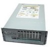
... Hitachi CF-3e board set and the Hitachi CF-3e chipset. AF001081 Figure 1. 1 Intel® Server System SR9000MK4U Chassis Overview The Intel® Server System SR9000MK4U as shown in cards; The system is a compact, high-density rack-mount server system with support for up to four Intel® Itanium® 2 processors and 256-GB DDR2 SDRAM memory. Intel® Server System SR9000MK4U Three Dimensional View Table 2.
... Hitachi CF-3e board set and the Hitachi CF-3e chipset. AF001081 Figure 1. 1 Intel® Server System SR9000MK4U Chassis Overview The Intel® Server System SR9000MK4U as shown in cards; The system is a compact, high-density rack-mount server system with support for up to four Intel® Itanium® 2 processors and 256-GB DDR2 SDRAM memory. Intel® Server System SR9000MK4U Three Dimensional View Table 2.

Product Guide
Page 24
... power cords (one cord per power supply). Chassis Feature Summary Feature Server Configuration Expansion and Servicing Management Upgrades Comment • Stand-alone system including external I/O PCI slots and disk expansion as needs grow • Support for Intel® Itanium® 2 processors • Support for 533 MHz Front... PCI-X* slots • Two x8 PCI-Express* slots • Two x16 PCI-Express slots • Up to the next generation Intel® Itanium® processor family • Multi-generational chassis 2 Intel® Server System SR9000MK4U Product Guide Table 3.
... power cords (one cord per power supply). Chassis Feature Summary Feature Server Configuration Expansion and Servicing Management Upgrades Comment • Stand-alone system including external I/O PCI slots and disk expansion as needs grow • Support for Intel® Itanium® 2 processors • Support for 533 MHz Front... PCI-X* slots • Two x8 PCI-Express* slots • Two x16 PCI-Express slots • Up to the next generation Intel® Itanium® processor family • Multi-generational chassis 2 Intel® Server System SR9000MK4U Product Guide Table 3.

Product Guide
Page 25
Hot-swap hard drive bay: hard drive LEDs - IO ports - Power supply indicators - Optical drive bay - Cooling fan - Memory box: Memory box serviceability LEDs • Chassis rear - Power supplies and AC inputs - Identification switch • Chassis top - PCI hot plug Intel® Server System SR9000MK4U Product Guide 3 Front panel: Front panel switches and LEDs - External Chassis Features System control buttons and indicators are located in several places on the chassis: • Chassis front - PCI slots -
Hot-swap hard drive bay: hard drive LEDs - IO ports - Power supply indicators - Optical drive bay - Cooling fan - Memory box: Memory box serviceability LEDs • Chassis rear - Power supplies and AC inputs - Identification switch • Chassis top - PCI hot plug Intel® Server System SR9000MK4U Product Guide 3 Front panel: Front panel switches and LEDs - External Chassis Features System control buttons and indicators are located in several places on the chassis: • Chassis front - PCI slots -

