Product Guide
Page 2
... intellectual property rights is used outside any patent, copyright or other intellectual property right. All Rights Reserved ii Intel® Server System SR9000MK4U Product Guide Intel's own chassis are not designed, intended or authorized for use of the Intel product could create a situation where personal injury or death may be held responsible if components fail or...
... intellectual property rights is used outside any patent, copyright or other intellectual property right. All Rights Reserved ii Intel® Server System SR9000MK4U Product Guide Intel's own chassis are not designed, intended or authorized for use of the Intel product could create a situation where personal injury or death may be held responsible if components fail or...

Product Guide
Page 3
...realizar cualquiera de las instrucciones. Vea Intel Server Boards and Server Chassis Safety Information en el Resource CD y/o en http://support.intel.com/support/motherboards/ server/sb/cs-010770.htm. Beachten Sie hierzu auch die Sicherheitshinweise zu Intel-Serverplatinen und Servergehäusen auf der... Resource CD oder unter http:// support.intel.com/support/motherboards/server/sb/cs-010770.htm. See also Intel Server Boards and Server Chassis Safety Information on the Resource CD and/or at http://support.intel.com/support/motherboards/server/sb/cs010770.htm. iii Safety Information ...
...realizar cualquiera de las instrucciones. Vea Intel Server Boards and Server Chassis Safety Information en el Resource CD y/o en http://support.intel.com/support/motherboards/ server/sb/cs-010770.htm. Beachten Sie hierzu auch die Sicherheitshinweise zu Intel-Serverplatinen und Servergehäusen auf der... Resource CD oder unter http:// support.intel.com/support/motherboards/server/sb/cs-010770.htm. See also Intel Server Boards and Server Chassis Safety Information on the Resource CD and/or at http://support.intel.com/support/motherboards/server/sb/cs010770.htm. iii Safety Information ...

Product Guide
Page 4
...After removing a board from its protective wrapper or from the server, place the board component side up on /off: The power button DOES NOT turn off the server and disconnect the power cord, telecommunications systems, networks, and modems attached to ensure and maintain compliance with...Heed safety instructions: Before working with your server when handling parts. To remove power from system, you are using this guide to the server before you perform all procedures in this guide or any components. iv Intel® Server System SR9000MK4U Product Guide Hold boards only by wearing an...
...After removing a board from its protective wrapper or from the server, place the board component side up on /off: The power button DOES NOT turn off the server and disconnect the power cord, telecommunications systems, networks, and modems attached to ensure and maintain compliance with...Heed safety instructions: Before working with your server when handling parts. To remove power from system, you are using this guide to the server before you perform all procedures in this guide or any components. iv Intel® Server System SR9000MK4U Product Guide Hold boards only by wearing an...

Product Guide
Page 5
grip the narrow sides of fine needle nosed pliers. Intel® Server System SR9000MK4U Product Guide v Installing or removing jumpers: A jumper is a small plastic encased conductor that jumper. If your jumpers do not have a small tab on top that ...
grip the narrow sides of fine needle nosed pliers. Intel® Server System SR9000MK4U Product Guide v Installing or removing jumpers: A jumper is a small plastic encased conductor that jumper. If your jumpers do not have a small tab on top that ...
Product Guide
Page 7
... features of a problem. Chapter 6 provides troubleshooting information. In this manual, see http:// support.intel.com/support/motherboards/server/SR9000MK4U/. Chapter 5 provides instructions on how to install, setup, and manage the system. Appendices provide tables of the boards used in the Server System SR9000MK4U. vii Chapter 2 provides an overview of the features of POST codes, SEL codes, safety...
... features of a problem. Chapter 6 provides troubleshooting information. In this manual, see http:// support.intel.com/support/motherboards/server/SR9000MK4U/. Chapter 5 provides instructions on how to install, setup, and manage the system. Appendices provide tables of the boards used in the Server System SR9000MK4U. vii Chapter 2 provides an overview of the features of POST codes, SEL codes, safety...
Product Guide
Page 8
..., processors, and third-party hardware have been tested with this product Use this Document or Software Intel® Server System SR9000MK4U Technical Product Specification Intel® Server System SR9000MK4U Quick Start User's Guide in the search field at http://support.intel.com/support/motherboards/server/SR9000MK4U/ Unless otherwise indicated in the table below, once on this product and need to search...
..., processors, and third-party hardware have been tested with this product Use this Document or Software Intel® Server System SR9000MK4U Technical Product Specification Intel® Server System SR9000MK4U Quick Start User's Guide in the search field at http://support.intel.com/support/motherboards/server/SR9000MK4U/ Unless otherwise indicated in the table below, once on this product and need to search...
Product Guide
Page 9
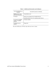
Table 1. Additional Information and Software For this information or software DIMMs that have been tested with this product For drivers For firmware and BIOS updates, or for BIOS recovery For diagnostics test software Use this Document or Software Tested Memory List Driver (for an extensive list of available drivers) Operating System Driver (for operating system drivers) Firmware Updates Diagnostics See also the Resource CD that came with your server system. Intel® Server System SR9000MK4U Product Guide ix
Table 1. Additional Information and Software For this information or software DIMMs that have been tested with this product For drivers For firmware and BIOS updates, or for BIOS recovery For diagnostics test software Use this Document or Software Tested Memory List Driver (for an extensive list of available drivers) Operating System Driver (for operating system drivers) Firmware Updates Diagnostics See also the Resource CD that came with your server system. Intel® Server System SR9000MK4U Product Guide ix

Product Guide
Page 10
... are disabled. Press the power button on the front panel. See your peripheral guides for information. 2. x Intel® Server System SR9000MK4U Product Guide Powering the System On and Off Powering On the System Power 1. If 100 - 110 VAC is forced off . The green power LED will force a power off... . Watch the fault LED on these peripherals. Note: The system will light. 4. See the troubleshooting information at the end of the system and to be used only if the system has locked up. When the system power is used, both power supplies must be turned on first...
... are disabled. Press the power button on the front panel. See your peripheral guides for information. 2. x Intel® Server System SR9000MK4U Product Guide Powering the System On and Off Powering On the System Power 1. If 100 - 110 VAC is forced off . The green power LED will force a power off... . Watch the fault LED on these peripherals. Note: The system will light. 4. See the troubleshooting information at the end of the system and to be used only if the system has locked up. When the system power is used, both power supplies must be turned on first...

Product Guide
Page 11
...Organization ...vii Product Accessories ...viii Additional Information and Software viii Powering the System On and Off x Powering On the System Power x Powering Off the System Power x Chapter 1: Intel® Server System SR9000MK4U Chassis Overview 1 Chassis Description ...2 External Chassis Features ...3 Chassis Front ...Internal Chassis Features ...12 Power Supply Subsystem 12 Cooling Subsystem ...14 PCI Card Slot ...15 Chapter 2: Intel® Server System SR9000MK4U Board Set Overview 17 Main Board ...18 Configuration Restrictions 22 Processor Configurations 23 Memory Box Card ...24 ...
...Organization ...vii Product Accessories ...viii Additional Information and Software viii Powering the System On and Off x Powering On the System Power x Powering Off the System Power x Chapter 1: Intel® Server System SR9000MK4U Chassis Overview 1 Chassis Description ...2 External Chassis Features ...3 Chassis Front ...Internal Chassis Features ...12 Power Supply Subsystem 12 Cooling Subsystem ...14 PCI Card Slot ...15 Chapter 2: Intel® Server System SR9000MK4U Board Set Overview 17 Main Board ...18 Configuration Restrictions 22 Processor Configurations 23 Memory Box Card ...24 ...

Product Guide
Page 12
... Backplane Cover 87 Removing the Hard Drive Backplane Cover 87 Installing the Hard Drive Backplane Cover 88 Installing and Removing the KVM Card 89 xii Intel® Server System SR9000MK4U Product Guide
... Backplane Cover 87 Removing the Hard Drive Backplane Cover 87 Installing the Hard Drive Backplane Cover 88 Installing and Removing the KVM Card 89 xii Intel® Server System SR9000MK4U Product Guide

Product Guide
Page 13
... 142 Execution Screen ...144 Using System Setup ...145 Starting Setup ...145 Recording Your Setup Settings 145 Navigating Setup Utility Screens 146 Primary Screens ...146 Configuring Serial-Over LAN 151 Chapter 5: Troubleshooting 153 Initial Troubleshooting Steps 153 Collecting System State Information 156 How to Read the POST Codes 159 Intel® Server System SR9000MK4U Product Guide xiii
... 142 Execution Screen ...144 Using System Setup ...145 Starting Setup ...145 Recording Your Setup Settings 145 Navigating Setup Utility Screens 146 Primary Screens ...146 Configuring Serial-Over LAN 151 Chapter 5: Troubleshooting 153 Initial Troubleshooting Steps 153 Collecting System State Information 156 How to Read the POST Codes 159 Intel® Server System SR9000MK4U Product Guide xiii

Product Guide
Page 14
...Warnings 198 System Access Warnings 199 Rack Mount Warnings 200 Electrostatic Discharge (ESD 200 Other Hazards ...201 Deutsch ...202 Sicherheitshinweise für den Server 202 ...Sicherheitshinweise und Vorsichtsmaßnahmen 202 Zielbenutzer der Anwendung 203 Standortauswahl ...203 Handhabung von Geräten 204 Warnungen zu Netzspannung und Elektrizität 204 Warnhinweise für den Systemzugang 205 Warnhinweise für Racks 206 Elektrostatische Entladungen (ESD 206 Andere Gefahren ...207 Français ...208 xiv Intel® Server System SR9000MK4U...
...Warnings 198 System Access Warnings 199 Rack Mount Warnings 200 Electrostatic Discharge (ESD 200 Other Hazards ...201 Deutsch ...202 Sicherheitshinweise für den Server 202 ...Sicherheitshinweise und Vorsichtsmaßnahmen 202 Zielbenutzer der Anwendung 203 Standortauswahl ...203 Handhabung von Geräten 204 Warnungen zu Netzspannung und Elektrizität 204 Warnhinweise für den Systemzugang 205 Warnhinweise für Racks 206 Elektrostatische Entladungen (ESD 206 Andere Gefahren ...207 Français ...208 xiv Intel® Server System SR9000MK4U...

Product Guide
Page 17
... Hard Drive 39 Figure 27. Hard Drive LED Indicators 42 Figure 31. Locating the Optical Drive Installation Position 53 Intel® Server System SR9000MK4U Product Guide xvii Front Panel Controls and Indicators 5 Figure 4. Main Board Layout 18 Figure 14. Removing the Top ...DIMM Installation Pattern 48 Figure 37. Memory Box Front View 46 Figure 36. Removing the Optical Drive Filler Panel 51 Figure 40. Intel® Server System SR9000MK4U Three Dimensional View 1 Figure 2. List of Memory Box 25 Figure 17. Chassis Front View ...4 Figure 3. Hard Drive Carrier ...
... Hard Drive 39 Figure 27. Hard Drive LED Indicators 42 Figure 31. Locating the Optical Drive Installation Position 53 Intel® Server System SR9000MK4U Product Guide xvii Front Panel Controls and Indicators 5 Figure 4. Main Board Layout 18 Figure 14. Removing the Top ...DIMM Installation Pattern 48 Figure 37. Memory Box Front View 46 Figure 36. Removing the Optical Drive Filler Panel 51 Figure 40. Intel® Server System SR9000MK4U Three Dimensional View 1 Figure 2. List of Memory Box 25 Figure 17. Chassis Front View ...4 Figure 3. Hard Drive Carrier ...

Product Guide
Page 18
... the Power Supply into Place 85 Figure 87. Lifting the Power Supply Box from Server 53 Figure 44. Loosening the Power Supply Support Captive Screws 84 Figure 85. Removing Optical Drive from System 79 Figure 78. PCI Tail Lock ...61 Figure 54. Releasing the PCI Card ... into Place 80 Figure 80. Setting the Power Supply Support into Place 70 Figure 67. Installing the Hard Drive Backplane Cover 88 xviii Intel® Server System SR9000MK4U Product Guide Installing a PCI Card 61 Figure 55. Opening a PCI Caution Plate 63 Figure 58. Unlocking a PCI Card Lock 64 Figure...
... the Power Supply into Place 85 Figure 87. Lifting the Power Supply Box from Server 53 Figure 44. Loosening the Power Supply Support Captive Screws 84 Figure 85. Removing Optical Drive from System 79 Figure 78. PCI Tail Lock ...61 Figure 54. Releasing the PCI Card ... into Place 80 Figure 80. Setting the Power Supply Support into Place 70 Figure 67. Installing the Hard Drive Backplane Cover 88 xviii Intel® Server System SR9000MK4U Product Guide Installing a PCI Card 61 Figure 55. Opening a PCI Caution Plate 63 Figure 58. Unlocking a PCI Card Lock 64 Figure...

Product Guide
Page 19
...108. Loosening the MVR Screws 112 Figure 109. Installing the LGA Terminal Cover 122 Figure 123. Removing the Bolster Plate from the System 126 Figure 129. Lifting the Mounting Plate from the Processor 123 Figure 125. Attaching the Chassis Handles 129 Figure 131. FWUPDATE ...Figure 110. Installing the Handles onto the MVR 120 Figure 122. Connections Near Power Supply Box and PCI Card Divider 168 Intel® Server System SR9000MK4U Product Guide xix Attaching the Hard Drive Backplane to the Processor Assembly 120 Figure 121. Setting the Processor Assembly into Place ...
...108. Loosening the MVR Screws 112 Figure 109. Installing the LGA Terminal Cover 122 Figure 123. Removing the Bolster Plate from the System 126 Figure 129. Lifting the Mounting Plate from the Processor 123 Figure 125. Attaching the Chassis Handles 129 Figure 131. FWUPDATE ...Figure 110. Installing the Handles onto the MVR 120 Figure 122. Connections Near Power Supply Box and PCI Card Divider 168 Intel® Server System SR9000MK4U Product Guide xix Attaching the Hard Drive Backplane to the Processor Assembly 120 Figure 121. Setting the Processor Assembly into Place ...

Product Guide
Page 20
MVR Connectors 169 Figure 140. Caution: Memory Box Contains Hot Components 193 Figure 141. Caution: System Contains Areas of High Voltage 194 Figure 143. SATA Connections on Non Hot-swap Power Supply 195 Figure 144. IDE Connection and Cable Routing 169 Figure 139. Caution: Server System is Heavy 194 Figure 142. Warning: Voltage on Hard Drive Backplane 168 Figure 138. Figure 137. Warning: Voltage on Hot-swap Power Supply 195 xx Intel® Server System SR9000MK4U Product Guide
MVR Connectors 169 Figure 140. Caution: Memory Box Contains Hot Components 193 Figure 141. Caution: System Contains Areas of High Voltage 194 Figure 143. SATA Connections on Non Hot-swap Power Supply 195 Figure 144. IDE Connection and Cable Routing 169 Figure 139. Caution: Server System is Heavy 194 Figure 142. Warning: Voltage on Hard Drive Backplane 168 Figure 138. Figure 137. Warning: Voltage on Hot-swap Power Supply 195 xx Intel® Server System SR9000MK4U Product Guide

Product Guide
Page 21
...Panel Board Components 30 Table 17. Boot Maintenance Menu Options 132 Table 20. POST Codes Generated by SAL 179 Intel® Server System SR9000MK4U Product Guide xxi Memory Box Card Connectors 24 Table 14. Additional Information and Software viii Table 2. Supported Processor ...Segment LED ..........177 Table 33. Hard Drive Backplane Connectors 29 Table 16. Devices Screen ...149 Table 28. List of Tables Table 1. Server Physical Specifications 1 Table 3. Main Setup Screen 147 Table 25. Main Board Internal I /O Connectors 21 Table 9. Processor Screen 148 ...
...Panel Board Components 30 Table 17. Boot Maintenance Menu Options 132 Table 20. POST Codes Generated by SAL 179 Intel® Server System SR9000MK4U Product Guide xxi Memory Box Card Connectors 24 Table 14. Additional Information and Software viii Table 2. Supported Processor ...Segment LED ..........177 Table 33. Hard Drive Backplane Connectors 29 Table 16. Devices Screen ...149 Table 28. List of Tables Table 1. Server Physical Specifications 1 Table 3. Main Setup Screen 147 Table 25. Main Board Internal I /O Connectors 21 Table 9. Processor Screen 148 ...

Product Guide
Page 23
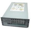
... hot-swap hard drives. hot-swap, redundant power supply modules; Intel® Server System SR9000MK4U Three Dimensional View Table 2. The system is a compact, high-density rack-mount server system with support for up to four Intel® Itanium® 2 processors and 256-GB DDR2 SDRAM memory. AF001081 Figure 1. Server Physical Specifications Characteristics Height Width Depth Weight Heat Dissipation Specifications...
... hot-swap hard drives. hot-swap, redundant power supply modules; Intel® Server System SR9000MK4U Three Dimensional View Table 2. The system is a compact, high-density rack-mount server system with support for up to four Intel® Itanium® 2 processors and 256-GB DDR2 SDRAM memory. AF001081 Figure 1. Server Physical Specifications Characteristics Height Width Depth Weight Heat Dissipation Specifications...

Product Guide
Page 24
... Synchronous Dynamic Random Access Memory (SDRAM) • Support for the server system to operate, and redundancy is used, both power supplies must be connected for PCI Express* x4/x8/x16 • Up to four Intel® Itanium® 2 processors • Up to 32 DIMM ...PCI-Express* slots • Two x16 PCI-Express slots • Up to the next generation Intel® Itanium® processor family • Multi-generational chassis 2 Intel® Server System SR9000MK4U Product Guide Chassis Description Features are outlined in a redundant power cords when using 200-240 VAC configuration...
... Synchronous Dynamic Random Access Memory (SDRAM) • Support for the server system to operate, and redundancy is used, both power supplies must be connected for PCI Express* x4/x8/x16 • Up to four Intel® Itanium® 2 processors • Up to 32 DIMM ...PCI-Express* slots • Two x16 PCI-Express slots • Up to the next generation Intel® Itanium® processor family • Multi-generational chassis 2 Intel® Server System SR9000MK4U Product Guide Chassis Description Features are outlined in a redundant power cords when using 200-240 VAC configuration...

Product Guide
Page 25
External Chassis Features System control buttons and indicators are located in several places on the chassis: • Chassis front - Optical drive bay - Hot-swap hard drive bay: hard drive LEDs - PCI slots - Identification switch • Chassis top - Memory box: Memory box serviceability LEDs • Chassis rear - Cooling fan - IO ports - PCI hot plug Intel® Server System SR9000MK4U Product Guide 3 Power supplies and AC inputs - Power supply indicators - Front panel: Front panel switches and LEDs -
External Chassis Features System control buttons and indicators are located in several places on the chassis: • Chassis front - Optical drive bay - Hot-swap hard drive bay: hard drive LEDs - PCI slots - Identification switch • Chassis top - Memory box: Memory box serviceability LEDs • Chassis rear - Cooling fan - IO ports - PCI hot plug Intel® Server System SR9000MK4U Product Guide 3 Power supplies and AC inputs - Power supply indicators - Front panel: Front panel switches and LEDs -

