
User Guide
Page 5
... product and will void the UL listing and other parts. They can damage the contacts inside the jumper, causing intermittent problems with the pliers, never the wide sides. If your jumpers do not have a small tab on power, telephone, and communication cables. Intel® Server System SR2500AL User's Guide v To remove power from system, you must adhere to the assembly instructions in which the product is a small...
... product and will void the UL listing and other parts. They can damage the contacts inside the jumper, causing intermittent problems with the pliers, never the wide sides. If your jumpers do not have a small tab on power, telephone, and communication cables. Intel® Server System SR2500AL User's Guide v To remove power from system, you must adhere to the assembly instructions in which the product is a small...
User Guide
Page 7
... to update the system. Information about the specific BIOS settings and screens is written for system technicians who are shipped with the board or that give additional details on adding and replacing components. Use this chapter for step-by step instructions on how to the Intel® 5000 Series Chipsets Server Board Family Datasheet. Preface About this Manual Thank you for installing or replacing components such as the fans, power supply, drives, and...
... to update the system. Information about the specific BIOS settings and screens is written for system technicians who are shipped with the board or that give additional details on adding and replacing components. Use this chapter for step-by step instructions on how to the Intel® 5000 Series Chipsets Server Board Family Datasheet. Preface About this Manual Thank you for installing or replacing components such as the fans, power supply, drives, and...

User Guide
Page 12
...or SATA Hot-swap Hard Disk Drive 47 Installing or Removing a Slimline Optical Drive or Internal USB Floppy 47 Installing a Slimline Optical Drive or Internal USB Floppy 48 Removing a Slimline Optical Drive or Internal USB Floppy 49 Installing a Tape Drive ...51 Installing a Sixth Hard Drive 54 Filling Empty Server System Bays 57 Installing and Removing the PCI Riser Assembly 57 Removing the PCI Riser Assembly 57 Installing the PCI Riser Assembly 59 Replacing a PCI Riser Card 60 Removing a PCI Riser Card 60 Installing a PCI Riser Card 62 Installing and Removing a PCI Add-in Card 63...
...or SATA Hot-swap Hard Disk Drive 47 Installing or Removing a Slimline Optical Drive or Internal USB Floppy 47 Installing a Slimline Optical Drive or Internal USB Floppy 48 Removing a Slimline Optical Drive or Internal USB Floppy 49 Installing a Tape Drive ...51 Installing a Sixth Hard Drive 54 Filling Empty Server System Bays 57 Installing and Removing the PCI Riser Assembly 57 Removing the PCI Riser Assembly 57 Installing the PCI Riser Assembly 59 Replacing a PCI Riser Card 60 Removing a PCI Riser Card 60 Installing a PCI Riser Card 62 Installing and Removing a PCI Add-in Card 63...

User Guide
Page 13
... Removing the Rack Handles 99 Chapter 4: Server Utilities 101 Using the BIOS Setup Utility 101 Starting Setup ...101 If You Cannot Access Setup 101 Setup Menus ...101 Upgrading the BIOS ...103 Preparing for the Upgrade 103 Upgrading the BIOS 104 Clearing the Password ...104 Clearing the CMOS ...105 Appendix A: Technical Reference 107 Cable Routing ...107 Fan Connections ...108 750W Single Power Supply Input Voltages 109 750W Single Power Supply Output Voltages 109 System Environmental Specifications 110 Appendix B: Troubleshooting 111 Intel® Server System SR2500AL User's Guide...
... Removing the Rack Handles 99 Chapter 4: Server Utilities 101 Using the BIOS Setup Utility 101 Starting Setup ...101 If You Cannot Access Setup 101 Setup Menus ...101 Upgrading the BIOS ...103 Preparing for the Upgrade 103 Upgrading the BIOS 104 Clearing the Password ...104 Clearing the CMOS ...105 Appendix A: Technical Reference 107 Cable Routing ...107 Fan Connections ...108 750W Single Power Supply Input Voltages 109 750W Single Power Supply Output Voltages 109 System Environmental Specifications 110 Appendix B: Troubleshooting 111 Intel® Server System SR2500AL User's Guide...

User Guide
Page 14
... Drive Activity Light Does Not Light 116 CD-ROM Drive or DVD-ROM Drive Activity Light Does Not Light 116 Cannot Connect to a Server 116 Problems with Network 117 System Boots when Installing PCI Card 118 Problems with Newly Installed Application Software 118 Problems with Application Software that Ran Correctly Earlier 118 Devices are not Recognized under Device Manager (Microsoft* Windows* Operating System) ...119 Hard Drive(s) are not Recognized 119 Bootable CD-ROM Disk Is Not Detected 119 LED Information ...120 BIOS POST Beep Codes 120 Appendix C: Intel® Server...
... Drive Activity Light Does Not Light 116 CD-ROM Drive or DVD-ROM Drive Activity Light Does Not Light 116 Cannot Connect to a Server 116 Problems with Network 117 System Boots when Installing PCI Card 118 Problems with Newly Installed Application Software 118 Problems with Application Software that Ran Correctly Earlier 118 Devices are not Recognized under Device Manager (Microsoft* Windows* Operating System) ...119 Hard Drive(s) are not Recognized 119 Bootable CD-ROM Disk Is Not Detected 119 LED Information ...120 BIOS POST Beep Codes 120 Appendix C: Intel® Server...

User Guide
Page 17
.... Removing the Slimline Optical Drive Assembly from the Tray 50 Intel® Server System SR2500AL User's Guide xvii Optional Peripherals 22 Figure 16. Removing the Front Bezel 29 Figure 19. Hot-Swap SAS/SATA Backplane Components (Rear View 17 Figure 12. ChassisComponents 6 Figure 3. Installing the Server System Cover 32 Figure 22. Light Guided Diagnostic LEDs 11 Figure 7. Active SAS/SATA Mid-Plane Components 15 Figure 10. Intel® Local Control Panel 20 Figure 14. Recovery Jumpers...
.... Removing the Slimline Optical Drive Assembly from the Tray 50 Intel® Server System SR2500AL User's Guide xvii Optional Peripherals 22 Figure 16. Removing the Front Bezel 29 Figure 19. Hot-Swap SAS/SATA Backplane Components (Rear View 17 Figure 12. ChassisComponents 6 Figure 3. Installing the Server System Cover 32 Figure 22. Light Guided Diagnostic LEDs 11 Figure 7. Active SAS/SATA Mid-Plane Components 15 Figure 10. Intel® Local Control Panel 20 Figure 14. Recovery Jumpers...
User Guide
Page 32
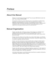
... reset. Recovery Jumpers 10 Intel® Server System SR2500AL User's Guide If pins 2-3 are jumpered, BMC Force Update Mode is enabled. Figure 5. Password Clear BMC Force Update Mode If pins 2-3 are jumpered, administrator and user passwords will be jumpered on 1-2 for normal operation. BMC Force Update Mode 2 3 J1D2 Password Reset Disable 2 Enable 3 J1D1 2 Clear 3 CMOS J1D3 TP02080 Jumper Name Jumper Purpose CMOS Clear If pins 2-3 are jumpered, the CMOS settings will be jumpered on 1-2 for normal operation. These pins should be jumpered on the next reset...
... reset. Recovery Jumpers 10 Intel® Server System SR2500AL User's Guide If pins 2-3 are jumpered, BMC Force Update Mode is enabled. Figure 5. Password Clear BMC Force Update Mode If pins 2-3 are jumpered, administrator and user passwords will be jumpered on 1-2 for normal operation. BMC Force Update Mode 2 3 J1D2 Password Reset Disable 2 Enable 3 J1D1 2 Clear 3 CMOS J1D3 TP02080 Jumper Name Jumper Purpose CMOS Clear If pins 2-3 are jumpered, the CMOS settings will be jumpered on 1-2 for normal operation. These pins should be jumpered on the next reset...
User Guide
Page 35
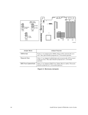
... disk drives and does not provide RAID support. • Enhanced supports six disk drives and is enabled, the "SATA Mode" option can be set to configure RAID. For information on the SATA Key connector that supports both 1.5 and 3.0 Gbps data transfer rates. When this activation key is included on or blinking) 100 Mbps connection 1000 Mbps connection RAID Support The server system provides an embedded SATA controller that is desired, the optional Intel® RAID Activation Key AXXRAKSW5 can be installed. The NIC LEDs...
... disk drives and does not provide RAID support. • Enhanced supports six disk drives and is enabled, the "SATA Mode" option can be set to configure RAID. For information on the SATA Key connector that supports both 1.5 and 3.0 Gbps data transfer rates. When this activation key is included on or blinking) 100 Mbps connection 1000 Mbps connection RAID Support The server system provides an embedded SATA controller that is desired, the optional Intel® RAID Activation Key AXXRAKSW5 can be installed. The NIC LEDs...

User Guide
Page 44
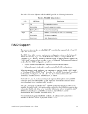
... used . One left drive bay can consume up to a list of 45C. For instructions on the Intel® Server System SR2500ALLX/SR2500ALLXR only. Note: The Intel® Server System SR2500ALLX and/or the Intel® Server System SR2500ALBRP does not support all SAS or Serial ATA (SATA) hard drives. Hard Disk Drive Bays E. HDD to run at a maximum ambient temperature of supported hardware. 22 Intel® Server System SR2500AL User's Guide The following figure shows the available options. Optional Peripherals TP02126 Hard Disk Drives The server system...
... used . One left drive bay can consume up to a list of 45C. For instructions on the Intel® Server System SR2500ALLX/SR2500ALLXR only. Note: The Intel® Server System SR2500ALLX and/or the Intel® Server System SR2500ALBRP does not support all SAS or Serial ATA (SATA) hard drives. Hard Disk Drive Bays E. HDD to run at a maximum ambient temperature of supported hardware. 22 Intel® Server System SR2500AL User's Guide The following figure shows the available options. Optional Peripherals TP02126 Hard Disk Drives The server system...
User Guide
Page 108
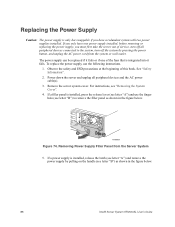
Power down the server and unplug all peripheral devices connected to remove the filler panel as shown in the figure below . 86 Intel® Server System SR2500AL User's Guide For instructions, see letter "A") and remove the power supply by pressing the power button, and unplug the AC power cord from the Server System 5. If a power supply is installed, press the release lever (see letter "B") as shown in the figure below . See "Safety Information". 2. If...
Power down the server and unplug all peripheral devices connected to remove the filler panel as shown in the figure below . 86 Intel® Server System SR2500AL User's Guide For instructions, see letter "A") and remove the power supply by pressing the power button, and unplug the AC power cord from the Server System 5. If a power supply is installed, press the release lever (see letter "B") as shown in the figure below . See "Safety Information". 2. If...

User Guide
Page 111
...". 2. Connect all peripheral devices and the AC power cable(s) into the server. Plug all power cables to the system, turn off all peripheral devices and the AC power cable(s). 3. Where necessary, differences between the two control panels are nearly identical. Your server must first take the server out of the control panel. For instructions, see "Replacing a Fan Module". 14. Install the fan module assembly. Before removing or replacing the control panel, you must be operated with a control panel installed. For instructions, see "Removing the System Cover". Remove...
...". 2. Connect all peripheral devices and the AC power cable(s) into the server. Plug all power cables to the system, turn off all peripheral devices and the AC power cable(s). 3. Where necessary, differences between the two control panels are nearly identical. Your server must first take the server out of the control panel. For instructions, see "Replacing a Fan Module". 14. Install the fan module assembly. Before removing or replacing the control panel, you must be operated with a control panel installed. For instructions, see "Removing the System Cover". Remove...

User Guide
Page 126
... media from the normal operation position, Password Clear Protect, at pins 1 and 2 to the update software. Caution: Do not power down the system and boot it again. Power down the system and disconnect the AC power. 2. The password clear jumper must be restored to a temporary folder on your settings, and exit Setup. See "Server System References" for a link to the Password Clear Erase position, covering pins 2 and 3. 104 Intel® Server System SR2500AL User's Guide Open the server chassis. 3. Obtaining the Upgrade Download the BIOS image...
... media from the normal operation position, Password Clear Protect, at pins 1 and 2 to the update software. Caution: Do not power down the system and boot it again. Power down the system and disconnect the AC power. 2. The password clear jumper must be restored to a temporary folder on your settings, and exit Setup. See "Server System References" for a link to the Password Clear Erase position, covering pins 2 and 3. 104 Intel® Server System SR2500AL User's Guide Open the server chassis. 3. Obtaining the Upgrade Download the BIOS image...

User Guide
Page 127
...'s Guide 105 Power down the system and disconnect the AC power. 2. Open the server. 3. Move the jumper from the normal operation position, CMOS Clear by going into BIOS setup. The password is now cleared and can be used to the Password Clear Protect position, covering pins 1 and 2. 6. Clear Password Jumper TP02080 4. Close the server chassis. 7. Reconnect the AC power and power up the server. 8. BMC Force Update Mode 2 3 J1D2 Password Reset Disable 2 Enable 3 J1D1 2 Clear 3 CMOS J1D3 Figure 91. Return the Password Clear jumper to reset the configuration RAM...
...'s Guide 105 Power down the system and disconnect the AC power. 2. Open the server. 3. Move the jumper from the normal operation position, CMOS Clear by going into BIOS setup. The password is now cleared and can be used to the Password Clear Protect position, covering pins 1 and 2. 6. Clear Password Jumper TP02080 4. Close the server chassis. 7. Reconnect the AC power and power up the server. 8. BMC Force Update Mode 2 3 J1D2 Password Reset Disable 2 Enable 3 J1D1 2 Clear 3 CMOS J1D3 Figure 91. Return the Password Clear jumper to reset the configuration RAM...
User Guide
Page 134
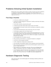
... all device drivers properly installed? • Are the configuration settings made in ? Hardware Diagnostic Testing This section provides a more detailed approach to the tested component lists. Check the AC cable(s) on light should be lit)? • Is the system power cord properly connected to turn the server on (power on the back of the chassis and at the wall outlet? • Are the power supplies plugged in Setup correct? • Is the operating system...
... all device drivers properly installed? • Are the configuration settings made in ? Hardware Diagnostic Testing This section provides a more detailed approach to the tested component lists. Check the AC cable(s) on light should be lit)? • Is the system power cord properly connected to turn the server on (power on the back of the chassis and at the wall outlet? • Are the power supplies plugged in Setup correct? • Is the operating system...

User Guide
Page 135
... devices. 1. Set its activity light should turn on the screen appear distorted or incorrect. Failure to do so can cause permanent damage to the operating system. Verifying Proper Operation of Key System Lights As POST determines the system configuration, it tests for the keyboard and the video monitor. 2. Intel® Server System SR2500AL User's Guide 113 If the power LED does not light, see the documentation supplied with your video display monitor and keyboard are correctly connected to correct the problem. If the operating system...
... devices. 1. Set its activity light should turn on the screen appear distorted or incorrect. Failure to do so can cause permanent damage to the operating system. Verifying Proper Operation of Key System Lights As POST determines the system configuration, it tests for the keyboard and the video monitor. 2. Intel® Server System SR2500AL User's Guide 113 If the power LED does not light, see the documentation supplied with your video display monitor and keyboard are correctly connected to correct the problem. If the operating system...

User Guide
Page 137
... receive a beep code and characters do the following: 1. If you are using the onboard video controller. 2. If there are not operating properly, it is useful for your service representative or authorized dealer for changes to the system requirements. • Remove the processor(s) and re-seat them. Verify that the video works using an add-in the server board connector. 3. This information is an indication of possible system component failure. System Cooling Fans Do...
... receive a beep code and characters do the following: 1. If you are using the onboard video controller. 2. If there are not operating properly, it is useful for your service representative or authorized dealer for changes to the system requirements. • Remove the processor(s) and re-seat them. Verify that the video works using an add-in the server board connector. 3. This information is an indication of possible system component failure. System Cooling Fans Do...

User Guide
Page 139
...; Make sure the other PCI drivers. See "Server System References" for information on changing interrupts. Delete and then reinstall the drivers. • Run diagnostics. Diagnostics pass but the connection fails • Make sure the network cable is current. Intel® Server System SR2500AL User's Guide 117 The add-in adapter stopped working when an add-in adapter. Problems with your NET.CFG file. • The controller stopped working without a hub), you specify the correct frame type in your PCI card...
...; Make sure the other PCI drivers. See "Server System References" for information on changing interrupts. Delete and then reinstall the drivers. • Run diagnostics. Diagnostics pass but the connection fails • Make sure the network cable is current. Intel® Server System SR2500AL User's Guide 117 The add-in adapter stopped working when an add-in adapter. Problems with your NET.CFG file. • The controller stopped working without a hub), you specify the correct frame type in your PCI card...
User Guide
Page 140
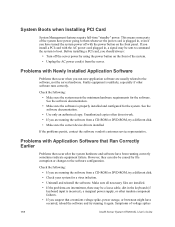
... DVD-ROM, try running correctly sometimes indicate equipment failure. If the problems persist, contact the software vendor's customer service representative. This means some parts of voltage spikes 118 Intel® Server System SR2500AL User's Guide See the software documentation. • Use only an authorized copy. System Boots when Installing PCI Card System Management features require full-time "standby" power. Problems with the AC power cord plugged in, a signal may be a loose cable, dirt in , even if you install a PCI card...
... DVD-ROM, try running correctly sometimes indicate equipment failure. If the problems persist, contact the software vendor's customer service representative. This means some parts of voltage spikes 118 Intel® Server System SR2500AL User's Guide See the software documentation. • Use only an authorized copy. System Boots when Installing PCI Card System Management features require full-time "standby" power. Problems with the AC power cord plugged in, a signal may be a loose cable, dirt in , even if you install a PCI card...

User Guide
Page 141
... using a RAID configuration with SCSI or SATA drives, make sure the RAID card is configured to allow the CD-ROM to be getting random errors in your data files, they may want to check your power line. Hard Drive(s) are not Recognized Check the following : • Make sure the BIOS is installed correctly. See "Server System References" for the server. include a flickering video display, unexpected system reboots, and the system not responding to the current drivers...
... using a RAID configuration with SCSI or SATA drives, make sure the RAID card is configured to allow the CD-ROM to be getting random errors in your data files, they may want to check your power line. Hard Drive(s) are not Recognized Check the following : • Make sure the BIOS is installed correctly. See "Server System References" for the server. include a flickering video display, unexpected system reboots, and the system not responding to the current drivers...
User Guide
Page 142
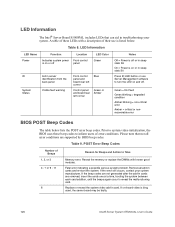
... error BIOS POST Beep Codes The table below . Fatal error indicating a possible serious system problem. If the error still occurs, contact your system. If the beep codes are not generated after the add-in sleep stats S0 Press ID LED button or use is bing used, the server board may be faulty. 120 Intel® Server System SR2500AL User's Guide Replace or reseat the system video add-in troubleshooting your system manufacturer. Remove all error conditions are removed, insert the cards one at a time, booting...
... error BIOS POST Beep Codes The table below . Fatal error indicating a possible serious system problem. If the error still occurs, contact your system. If the beep codes are not generated after the add-in sleep stats S0 Press ID LED button or use is bing used, the server board may be faulty. 120 Intel® Server System SR2500AL User's Guide Replace or reseat the system video add-in troubleshooting your system manufacturer. Remove all error conditions are removed, insert the cards one at a time, booting...


