User Guide
Page 7
... the fans, power supply, drives, and other components. Manual Organization Chapter 1 provides a list of this manual, see http:// support.intel.com/support/motherboards/server/chassis/SR2500/. Chapter 4 provides instructions on how to reset the password or CMOS. Chapter 2 provides a brief overview of the product, and product diagrams to update the system. This includes how to navigate through the BIOS Setup screens, how to perform a BIOS update, and how to add and replace components on the Intel® Server System...
... the fans, power supply, drives, and other components. Manual Organization Chapter 1 provides a list of this manual, see http:// support.intel.com/support/motherboards/server/chassis/SR2500/. Chapter 4 provides instructions on how to reset the password or CMOS. Chapter 2 provides a brief overview of the product, and product diagrams to update the system. This includes how to navigate through the BIOS Setup screens, how to perform a BIOS update, and how to add and replace components on the Intel® Server System...

User Guide
Page 12
...or SATA Hot-swap Hard Disk Drive 47 Installing or Removing a Slimline Optical Drive or Internal USB Floppy 47 Installing a Slimline Optical Drive or Internal USB Floppy 48 Removing a Slimline Optical Drive or Internal USB Floppy 49 Installing a Tape Drive ...51 Installing a Sixth Hard Drive 54 Filling Empty Server System Bays 57 Installing and Removing the PCI Riser Assembly 57 Removing the PCI Riser Assembly 57 Installing the PCI Riser Assembly 59 Replacing a PCI Riser Card 60 Removing a PCI Riser Card 60 Installing a PCI Riser Card 62 Installing and Removing a PCI Add-in Card 63...
...or SATA Hot-swap Hard Disk Drive 47 Installing or Removing a Slimline Optical Drive or Internal USB Floppy 47 Installing a Slimline Optical Drive or Internal USB Floppy 48 Removing a Slimline Optical Drive or Internal USB Floppy 49 Installing a Tape Drive ...51 Installing a Sixth Hard Drive 54 Filling Empty Server System Bays 57 Installing and Removing the PCI Riser Assembly 57 Removing the PCI Riser Assembly 57 Installing the PCI Riser Assembly 59 Replacing a PCI Riser Card 60 Removing a PCI Riser Card 60 Installing a PCI Riser Card 62 Installing and Removing a PCI Add-in Card 63...

User Guide
Page 13
... Removing the Rack Handles 99 Chapter 4: Server Utilities 101 Using the BIOS Setup Utility 101 Starting Setup ...101 If You Cannot Access Setup 101 Setup Menus ...101 Upgrading the BIOS ...103 Preparing for the Upgrade 103 Upgrading the BIOS 104 Clearing the Password ...104 Clearing the CMOS ...105 Appendix A: Technical Reference 107 Cable Routing ...107 Fan Connections ...108 750W Single Power Supply Input Voltages 109 750W Single Power Supply Output Voltages 109 System Environmental Specifications 110 Appendix B: Troubleshooting 111 Intel® Server System SR2500AL User's Guide...
... Removing the Rack Handles 99 Chapter 4: Server Utilities 101 Using the BIOS Setup Utility 101 Starting Setup ...101 If You Cannot Access Setup 101 Setup Menus ...101 Upgrading the BIOS ...103 Preparing for the Upgrade 103 Upgrading the BIOS 104 Clearing the Password ...104 Clearing the CMOS ...105 Appendix A: Technical Reference 107 Cable Routing ...107 Fan Connections ...108 750W Single Power Supply Input Voltages 109 750W Single Power Supply Output Voltages 109 System Environmental Specifications 110 Appendix B: Troubleshooting 111 Intel® Server System SR2500AL User's Guide...

User Guide
Page 14
... Drive Activity Light Does Not Light 116 CD-ROM Drive or DVD-ROM Drive Activity Light Does Not Light 116 Cannot Connect to a Server 116 Problems with Network 117 System Boots when Installing PCI Card 118 Problems with Newly Installed Application Software 118 Problems with Application Software that Ran Correctly Earlier 118 Devices are not Recognized under Device Manager (Microsoft* Windows* Operating System) ...119 Hard Drive(s) are not Recognized 119 Bootable CD-ROM Disk Is Not Detected 119 LED Information ...120 BIOS POST Beep Codes 120 Appendix C: Intel® Server...
... Drive Activity Light Does Not Light 116 CD-ROM Drive or DVD-ROM Drive Activity Light Does Not Light 116 Cannot Connect to a Server 116 Problems with Network 117 System Boots when Installing PCI Card 118 Problems with Newly Installed Application Software 118 Problems with Application Software that Ran Correctly Earlier 118 Devices are not Recognized under Device Manager (Microsoft* Windows* Operating System) ...119 Hard Drive(s) are not Recognized 119 Bootable CD-ROM Disk Is Not Detected 119 LED Information ...120 BIOS POST Beep Codes 120 Appendix C: Intel® Server...

User Guide
Page 17
List of Figures Figure 1. BIOS Select Jumper 9 Figure 5. Hot-Swap SAS/SATA Backplane Components (Rear View 17 Figure 12. Server System Back 21 Figure 15. Front Bezel Supporting the Intel® Local Control Panel 28 Figure 18. Installing the Memory 36 Figure 26. Installing the Processor 38 Figure 28. Removing the Small Air Baffle 41 Figure 31. Removing Hot-swap Disk Carrier from Drive Carrier 45 Figure 36. Removing Retention Device from...
List of Figures Figure 1. BIOS Select Jumper 9 Figure 5. Hot-Swap SAS/SATA Backplane Components (Rear View 17 Figure 12. Server System Back 21 Figure 15. Front Bezel Supporting the Intel® Local Control Panel 28 Figure 18. Installing the Memory 36 Figure 26. Installing the Processor 38 Figure 28. Removing the Small Air Baffle 41 Figure 31. Removing Hot-swap Disk Carrier from Drive Carrier 45 Figure 36. Removing Retention Device from...
User Guide
Page 32
...will be cleared on the next reset. Figure 5. These pins should be cleared on the next reset. These pins should be jumpered on 1-2 for normal operation. These pins should be jumpered on 1-2 for normal operation. If pins 2-3 are jumpered, BMC Force Update Mode is enabled. BMC Force Update Mode 2 3 J1D2 Password Reset Disable 2 Enable 3 J1D1 2 Clear 3 CMOS J1D3 TP02080 Jumper Name Jumper Purpose CMOS Clear If pins 2-3 are jumpered, the CMOS settings will be jumpered on 1-2 for normal operation. Recovery Jumpers 10 Intel® Server System SR2500AL User's Guide
...will be cleared on the next reset. Figure 5. These pins should be cleared on the next reset. These pins should be jumpered on 1-2 for normal operation. These pins should be jumpered on 1-2 for normal operation. If pins 2-3 are jumpered, BMC Force Update Mode is enabled. BMC Force Update Mode 2 3 J1D2 Password Reset Disable 2 Enable 3 J1D1 2 Clear 3 CMOS J1D3 TP02080 Jumper Name Jumper Purpose CMOS Clear If pins 2-3 are jumpered, the CMOS settings will be jumpered on 1-2 for normal operation. Recovery Jumpers 10 Intel® Server System SR2500AL User's Guide
User Guide
Page 35
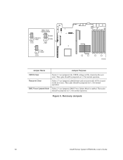
... for RAID configurations. The BIOS Setup utility provides multiple drive configuration options on the Advanced | ATA Controller setup page, some of which affect the ability to enable or disable "AHCI Mode" or "Configure SATA as follows: • Legacy supports four disk drives and does not provide RAID support. • Enhanced supports six disk drives and is desired, the optional Intel® RAID Activation Key AXXRAKSW5 can be installed. Intel® Server System SR2500AL User's Guide 13 When this option is enabled by default. The Intel® Embedded Server RAID...
... for RAID configurations. The BIOS Setup utility provides multiple drive configuration options on the Advanced | ATA Controller setup page, some of which affect the ability to enable or disable "AHCI Mode" or "Configure SATA as follows: • Legacy supports four disk drives and does not provide RAID support. • Enhanced supports six disk drives and is desired, the optional Intel® RAID Activation Key AXXRAKSW5 can be installed. Intel® Server System SR2500AL User's Guide 13 When this option is enabled by default. The Intel® Embedded Server RAID...

User Guide
Page 44
...Note: The Intel® Server System SR2500ALLX and/or the Intel® Server System SR2500ALBRP does not support all SAS or Serial ATA (SATA) hard drives. A. Tape Drive Filler Panel C. 6th HDD or Tape Drive Bay (Optional) D. HDD to a list of 45C. See "Server System References" for installing hard drives, a USB floppy drive, CD-ROM drive, or DVD-ROM drive. Drives must be used . A B E D C . For instructions on the Intel® Server System SR2500ALLX/SR2500ALLXR only. Hard Disk Drive Bays E. Peripheral Devices The server system provides locations and hardware for an...
...Note: The Intel® Server System SR2500ALLX and/or the Intel® Server System SR2500ALBRP does not support all SAS or Serial ATA (SATA) hard drives. A. Tape Drive Filler Panel C. 6th HDD or Tape Drive Bay (Optional) D. HDD to a list of 45C. See "Server System References" for installing hard drives, a USB floppy drive, CD-ROM drive, or DVD-ROM drive. Drives must be used . A B E D C . For instructions on the Intel® Server System SR2500ALLX/SR2500ALLXR only. Hard Disk Drive Bays E. Peripheral Devices The server system provides locations and hardware for an...

User Guide
Page 69
... instructions, see "Removing the Front Bezel". 2. For instructions, see "Installing the Front Bezel". 11. To maintain proper system cooling, a filler blank must be installed if you removed from the carrier. Install the server system cover. Intel® Server System SR2500AL User's Guide 47 Do not push on it . 8. Removing a SAS or SATA Hot-swap Hard Disk Drive 1. Remove the front bezel if it is installed in on the carrier for future use. 7. With the black...
... instructions, see "Removing the Front Bezel". 2. For instructions, see "Installing the Front Bezel". 11. To maintain proper system cooling, a filler blank must be installed if you removed from the carrier. Install the server system cover. Intel® Server System SR2500AL User's Guide 47 Do not push on it . 8. Removing a SAS or SATA Hot-swap Hard Disk Drive 1. Remove the front bezel if it is installed in on the carrier for future use. 7. With the black...
User Guide
Page 108
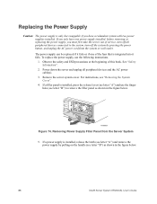
... Intel® Server System SR2500AL User's Guide For instructions, see letter "B") to the system, turn off all peripheral devices and the AC power cable(s). 3. B A AF000021 Figure 74. Observe the safety and ESD precautions at the beginning of this book. Remove the server system cover. If a filler panel is installed, press the release lever (see letter "A") and use the following instructions. 1. Removing Power Supply Filler Panel from the system or wall outlet. If a power supply is installed, release...
... Intel® Server System SR2500AL User's Guide For instructions, see letter "B") to the system, turn off all peripheral devices and the AC power cable(s). 3. B A AF000021 Figure 74. Observe the safety and ESD precautions at the beginning of this book. Remove the server system cover. If a filler panel is installed, press the release lever (see letter "A") and use the following instructions. 1. Removing Power Supply Filler Panel from the system or wall outlet. If a power supply is installed, release...

User Guide
Page 111
... AC power cable(s) into the server. For instructions, see "Replacing a Fan Module". 14. Connect all peripheral devices and the AC power cable(s). 3. Replacing the Control Panel The steps for both varieties of the control panel. Caution: The control panel is installed. Power down the server and unplug all power cables to the system, turn off the system by pressing the power button, and unplug the AC power cord from the system or wall outlet. 1. Intel® Server System SR2500AL User's Guide 89 For instructions, see "Removing...
... AC power cable(s) into the server. For instructions, see "Replacing a Fan Module". 14. Connect all peripheral devices and the AC power cable(s). 3. Replacing the Control Panel The steps for both varieties of the control panel. Caution: The control panel is installed. Power down the server and unplug all power cables to the system, turn off the system by pressing the power button, and unplug the AC power cord from the system or wall outlet. 1. Intel® Server System SR2500AL User's Guide 89 For instructions, see "Removing...

User Guide
Page 119
... the right and pointing down the server and unplug all peripheral devices connected to the system, turn off the system by pressing the power button, and unplug the AC power cord from the Fixed Fan Module 6. Use the steps below ). 3 2 1 A Figure 87. Remove the fan module assembly. With the fan oriented correctly, insert the fan into the power supply cannot be replaced. For instructions, see letter "A" in the figure...
... the right and pointing down the server and unplug all peripheral devices connected to the system, turn off the system by pressing the power button, and unplug the AC power cord from the Fixed Fan Module 6. Use the steps below ). 3 2 1 A Figure 87. Remove the fan module assembly. With the fan oriented correctly, insert the fan into the power supply cannot be replaced. For instructions, see letter "A" in the figure...

User Guide
Page 126
... your settings, and exit Setup. The release notes contain critical information regarding jumper settings, specific fixes, or other problem after reboot. When the update completes, remove the bootable media from the normal operation position, Password Clear Protect, at pins 1 and 2 to complete the upgrade. Clearing the Password If the user or administrator password(s) is completed. CMOS checksum errors require that came with the BIOS image file before a new password(s) can be restored to the update software. See "Server System References...
... your settings, and exit Setup. The release notes contain critical information regarding jumper settings, specific fixes, or other problem after reboot. When the update completes, remove the bootable media from the normal operation position, Password Clear Protect, at pins 1 and 2 to complete the upgrade. Clearing the Password If the user or administrator password(s) is completed. CMOS checksum errors require that came with the BIOS image file before a new password(s) can be restored to the update software. See "Server System References...

User Guide
Page 127
... AC power. 2. Clear Password Jumper TP02080 4. Return the Password Clear jumper to the CMOS Clear Force Erase position, covering pins 2 and 3. Intel® Server System SR2500AL User's Guide 105 Clearing the CMOS If you are not able to access the BIOS setup screens, the CMOS Clear jumper will need to be reset by BMC, at pins 1 and 2 to the Password Clear Protect position, covering pins 1 and 2. 6. Close the server chassis. 7. Reconnect the AC power and power up the server. 8. BMC Force Update Mode 2 3 J1D2 Password Reset Disable 2 Enable 3 J1D1 2 Clear 3 CMOS J1D3...
... AC power. 2. Clear Password Jumper TP02080 4. Return the Password Clear jumper to the CMOS Clear Force Erase position, covering pins 2 and 3. Intel® Server System SR2500AL User's Guide 105 Clearing the CMOS If you are not able to access the BIOS setup screens, the CMOS Clear jumper will need to be reset by BMC, at pins 1 and 2 to the Password Clear Protect position, covering pins 1 and 2. 6. Close the server chassis. 7. Reconnect the AC power and power up the server. 8. BMC Force Update Mode 2 3 J1D2 Password Reset Disable 2 Enable 3 J1D1 2 Clear 3 CMOS J1D3...
User Guide
Page 134
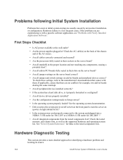
Hardware failure is a less frequent cause. To check these settings, refer to identifying a hardware problem and locating its source. 112 Intel® Server System SR2500AL User's Guide Hardware Diagnostic Testing This section provides a more detailed approach to the manufacturer's documentation that comes with Newly Installed Application Software". First Steps Checklist • Is AC power available at the wall outlet? • Are the power supplies plugged in Setup correct? • Is the operating system properly...
Hardware failure is a less frequent cause. To check these settings, refer to identifying a hardware problem and locating its source. 112 Intel® Server System SR2500AL User's Guide Hardware Diagnostic Testing This section provides a more detailed approach to the manufacturer's documentation that comes with Newly Installed Application Software". First Steps Checklist • Is AC power available at the wall outlet? • Are the power supplies plugged in Setup correct? • Is the operating system properly...

User Guide
Page 135
... the Operating System Once the system boots up, the operating system prompt appears on the system. Intel® Server System SR2500AL User's Guide 113 Make sure your video display monitor). 4. If the power LED does light, attempt to be the first bootable device." Set its activity light should turn on Screen". If the power LED does not light, see "Drive Activity Light Does Not Light". • If system LEDs are correctly connected to correct the problem. If not, see "Power Light Does Not Light". for these specific problems: • Power light...
... the Operating System Once the system boots up, the operating system prompt appears on the system. Intel® Server System SR2500AL User's Guide 113 Make sure your video display monitor). 4. If the power LED does light, attempt to be the first bootable device." Set its activity light should turn on Screen". If the power LED does not light, see "Drive Activity Light Does Not Light". • If system LEDs are correctly connected to correct the problem. If not, see "Power Light Does Not Light". for these specific problems: • Power light...

User Guide
Page 139
... drivers are loaded • Certain drivers may require interrupts that interrupts are not shared. Diagnostics pass but the connection fails • Make sure the network cable is current. Intel® Server System SR2500AL User's Guide 117 See "Server System References" for information on changing interrupts. Make sure your PCI card(s) for a link to alter settings so that are not shared with your operating system supports shared interrupts. • Try reseating the add-in adapter...
... drivers are loaded • Certain drivers may require interrupts that interrupts are not shared. Diagnostics pass but the connection fails • Make sure the network cable is current. Intel® Server System SR2500AL User's Guide 117 See "Server System References" for information on changing interrupts. Make sure your PCI card(s) for a link to alter settings so that are not shared with your operating system supports shared interrupts. • Try reseating the add-in adapter...
User Guide
Page 140
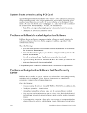
... turned the system power off the server power by file corruption or changes to them whenever the power cord is plugged in the keyboard (if keyboard input is incorrect), a marginal power supply, or other software runs correctly. Problems with the power button on the front of voltage spikes 118 Intel® Server System SR2500AL User's Guide See the software documentation. • Make sure the software is unlikely, especially if other random component failures. • If you install a PCI card...
... turned the system power off the server power by file corruption or changes to them whenever the power cord is plugged in the keyboard (if keyboard input is incorrect), a marginal power supply, or other software runs correctly. Problems with the power button on the front of voltage spikes 118 Intel® Server System SR2500AL User's Guide See the software documentation. • Make sure the software is unlikely, especially if other random component failures. • If you install a PCI card...

User Guide
Page 141
... connected correctly and that each SCSI ID number is installed correctly. See your drive documentation for details on setting the master/slave settings. • If using a RAID configuration with SCSI or SATA drives, make sure the RAID card is unique on your drives. • If using SCSI drives, verify that is plugged into the power supply. • Make sure the drive is configured to allow the CD-ROM to be the first bootable device. Intel® Server System...
... connected correctly and that each SCSI ID number is installed correctly. See your drive documentation for details on setting the master/slave settings. • If using a RAID configuration with SCSI or SATA drives, make sure the RAID card is unique on your drives. • If using SCSI drives, verify that is plugged into the power supply. • Make sure the drive is configured to allow the CD-ROM to be the first bootable device. Intel® Server System...
User Guide
Page 142
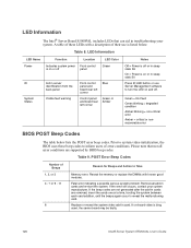
... Control panel and board rear left corner Blue Green or Amber Notes Off = Power is off or in sleep stats S0 Press ID LED button or use is on -board video is bing used, the server board may be faulty. 120 Intel® Server System SR2500AL User's Guide Green = No Fault Green blinking = degraded condition Amber blinking = non-critical error Amber = critical or nonrecoverable error BIOS POST Beep Codes The table below . Remove all error conditions are supported by BIOS beep codes. Replace...
... Control panel and board rear left corner Blue Green or Amber Notes Off = Power is off or in sleep stats S0 Press ID LED button or use is on -board video is bing used, the server board may be faulty. 120 Intel® Server System SR2500AL User's Guide Green = No Fault Green blinking = degraded condition Amber blinking = non-critical error Amber = critical or nonrecoverable error BIOS POST Beep Codes The table below . Remove all error conditions are supported by BIOS beep codes. Replace...


