Service Guide
Page 3
... may need, troubleshooting information, and instructions on how to help you identify components and their locations. This document provides a brief overview of the features of the board/chassis, a list of the product, and product diagrams to add and replace components on using the Intel® Server System SR1690WB. Use this server board. Manual Organization Chapter 1 provides a list of the Intel® Server System SR1690WB. Chapter 3 provides instructions on the Intel® Server System SR1690WB. In this manual provides technical specifications, regulatory...
... may need, troubleshooting information, and instructions on how to help you identify components and their locations. This document provides a brief overview of the features of the board/chassis, a list of the product, and product diagrams to add and replace components on using the Intel® Server System SR1690WB. Use this server board. Manual Organization Chapter 1 provides a list of the Intel® Server System SR1690WB. Chapter 3 provides instructions on the Intel® Server System SR1690WB. In this manual provides technical specifications, regulatory...
Service Guide
Page 4
... server system product box • Quick Start User's Guide, in the server system product box • Intel® Server Deployment Toolkit 3.0 CD • Hardware accessary bag, described as below . Two STS-100P processor heatsinks for your server: • One or two Intel® Xeon 5500 series and Intel® Xeon 5600 series processors • DDR3 RDIMM/UDIMM Memory • Hard drive • Slimline CD-ROM or DVD-ROM drive • RAID controller add-in card iv Intel® Server System SR1690WB Service Guide Intel® Server System SR1690WB...
... server system product box • Quick Start User's Guide, in the server system product box • Intel® Server Deployment Toolkit 3.0 CD • Hardware accessary bag, described as below . Two STS-100P processor heatsinks for your server: • One or two Intel® Xeon 5500 series and Intel® Xeon 5600 series processors • DDR3 RDIMM/UDIMM Memory • Hard drive • Slimline CD-ROM or DVD-ROM drive • RAID controller add-in card iv Intel® Server System SR1690WB Service Guide Intel® Server System SR1690WB...

Service Guide
Page 8
... that you can damage the contacts inside the jumper, causing intermittent problems with the function controlled by that jumper. Turn off the system AC power. Electrostatic discharge (ESD) and ESD protection: ESD can result. Do not slide board over two jumper pins. viii Intel® Server System SR1690WB Service Guide To remove power from system, you must adhere to the assembly instructions in this guide to chassis ground-any other regulatory approvals...
... that you can damage the contacts inside the jumper, causing intermittent problems with the function controlled by that jumper. Turn off the system AC power. Electrostatic discharge (ESD) and ESD protection: ESD can result. Do not slide board over two jumper pins. viii Intel® Server System SR1690WB Service Guide To remove power from system, you must adhere to the assembly instructions in this guide to chassis ground-any other regulatory approvals...
Service Guide
Page 9
... 8 Internal Components ...8 Server Board Connector and Component Locations 9 Configuration Jumpers ...11 Intel® Light Guided Diagnostics 13 Back Panel Connectors ...15 RAID Support ...16 Front Panel of Server System 17 Standard Control Panel 17 Rear of Server System ...19 Peripheral Devices ...19 Hard Disk Drives ...20 Slimline Optical Drive latch 20 Rack-Mounted Systems ...20 Hardware Requirements ...21 Processor ...21 Memory ...21 Memory Sparing and Mirroring 22 Power Supply ...23 Optional Hardware ...23 Intel® RAID Activation Key 23 Intel® Remote Management Module...
... 8 Internal Components ...8 Server Board Connector and Component Locations 9 Configuration Jumpers ...11 Intel® Light Guided Diagnostics 13 Back Panel Connectors ...15 RAID Support ...16 Front Panel of Server System 17 Standard Control Panel 17 Rear of Server System ...19 Peripheral Devices ...19 Hard Disk Drives ...20 Slimline Optical Drive latch 20 Rack-Mounted Systems ...20 Hardware Requirements ...21 Processor ...21 Memory ...21 Memory Sparing and Mirroring 22 Power Supply ...23 Optional Hardware ...23 Intel® RAID Activation Key 23 Intel® Remote Management Module...

Service Guide
Page 10
...Replacing a Processor 34 Installing and Removing a Hot-swap Hard Drive 35 Installing a SAS or SATA Hot-swap Hard Disk Drive 35 Removing a SAS or SATA Hot-swap Hard Disk Drive 38 Installing or Removing a Slimline Optical Drive 38 Installing a Slimline Optical Drive 38 Removing a Slimline Optical Drive 41 Installing and Removing the PCI Riser Assembly 41 Removing the PCI Riser Assembly 41 Installing the PCI Riser Assembly 41 Installing and Removing a PCI Add-In Card 42 Installing a PCI Add-In Card 42 Removing a PCI Add-In Card 43 Removing and Installing the System Fans 44 Replacing...
...Replacing a Processor 34 Installing and Removing a Hot-swap Hard Drive 35 Installing a SAS or SATA Hot-swap Hard Disk Drive 35 Removing a SAS or SATA Hot-swap Hard Disk Drive 38 Installing or Removing a Slimline Optical Drive 38 Installing a Slimline Optical Drive 38 Removing a Slimline Optical Drive 41 Installing and Removing the PCI Riser Assembly 41 Removing the PCI Riser Assembly 41 Installing the PCI Riser Assembly 41 Installing and Removing a PCI Add-In Card 42 Installing a PCI Add-In Card 42 Removing a PCI Add-In Card 43 Removing and Installing the System Fans 44 Replacing...

Service Guide
Page 11
Replacing the Backup Battery 56 Replacing the Power Supply 57 Removing the Power Supply 57 Installing the Power Supply 58 Installing and Removing the Rack Handles 59 Installing the Rack Handles 59 Removing the Rack Handles 60 Chapter 4: Server Utilities 61 Using the BIOS Setup Utility 61 Starting Setup ...61 If You Cannot Access Setup 61 Setup Menus ...61 Upgrading the BIOS ...63 Preparing for the Upgrade 63 Upgrading the BIOS ...64 Clearing the CMOS ...64 Resetting the Password ...65 Appendix A: Technical Reference 67 650-W Single Power Supply Input...
Replacing the Backup Battery 56 Replacing the Power Supply 57 Removing the Power Supply 57 Installing the Power Supply 58 Installing and Removing the Rack Handles 59 Installing the Rack Handles 59 Removing the Rack Handles 60 Chapter 4: Server Utilities 61 Using the BIOS Setup Utility 61 Starting Setup ...61 If You Cannot Access Setup 61 Setup Menus ...61 Upgrading the BIOS ...63 Preparing for the Upgrade 63 Upgrading the BIOS ...64 Clearing the CMOS ...64 Resetting the Password ...65 Appendix A: Technical Reference 67 650-W Single Power Supply Input...

Service Guide
Page 15
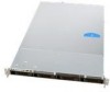
...; Server System SR1690WB Service Guide xv List of Figures Figure 1. Aligning the Processor 33 Figure 22. Replacing the system fans 45 Figure 36. Installing the I /O Connector Locations 19 Figure 10. Installing the Intel® RMM3 and Intel® RMM3 NIC 50 Figure 41. Intel® Server System SR1690WB 3 Figure 2. Installing the Memory 30 Figure 18. Pulling out the back lever 36 Figure 25. 2.5 HDD Installation 36 Figure 26. 3.5 HDD Installation 37 Figure 27. Removing a PCI Card in Bezel for Optical Opening...
...; Server System SR1690WB Service Guide xv List of Figures Figure 1. Aligning the Processor 33 Figure 22. Replacing the system fans 45 Figure 36. Installing the I /O Connector Locations 19 Figure 10. Installing the Intel® RMM3 and Intel® RMM3 NIC 50 Figure 41. Intel® Server System SR1690WB 3 Figure 2. Installing the Memory 30 Figure 18. Pulling out the back lever 36 Figure 25. 2.5 HDD Installation 36 Figure 26. 3.5 HDD Installation 37 Figure 27. Removing a PCI Card in Bezel for Optical Opening...
Service Guide
Page 22
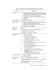
...- One low-profile USB 2x5 pin - SATA SW RAID 5 Activation Key Connector - Intel® Server System SR1690WB Feature Summary Feature Processor Memory Capacity Memory Type DIMM Slots Chipset System Connectors/ Headers System Fan Support Add-in FC-LGA 1366 Socket B package with presence detection to support optional Intel® Remote Management Module 3 - DB-15 Video connectors - RJ-45 serial Port A connector - Six SATA II connectors - One SSI-EEB compliant front panel header • Two sets of CPU fans • Two sets of DIMM fans Intel® Server Board S5500WB SSI-compliant...
...- One low-profile USB 2x5 pin - SATA SW RAID 5 Activation Key Connector - Intel® Server System SR1690WB Feature Summary Feature Processor Memory Capacity Memory Type DIMM Slots Chipset System Connectors/ Headers System Fan Support Add-in FC-LGA 1366 Socket B package with presence detection to support optional Intel® Remote Management Module 3 - DB-15 Video connectors - RJ-45 serial Port A connector - Six SATA II connectors - One SSI-EEB compliant front panel header • Two sets of CPU fans • Two sets of DIMM fans Intel® Server Board S5500WB SSI-compliant...

Service Guide
Page 27
... Board Connector and Component Locations A B CD E F PP G OO H NN MM I /O Expansion Module W. 8-pin CPU Connector Connectors B. Remote Management Module 3 Y. 4-pin Fan Connector (CPU2) D. USB Connector BB. 8-pin Fan Connector (MEM2R) Intel® Server System SR1690WB Service Guide 9 Dual Intel® I LL KK J JJ K II L HH GG EE CC AA Y X FF DD BB Z W U SQ O M V T RP N AF003212 Description Description A. External I/O AA. 4-pin Fan Connector (MEM2) F. POST Code LEDs Z. 4-pin Fan Connector (CPU2A) E. Processor Socket 2 C. PCI...
... Board Connector and Component Locations A B CD E F PP G OO H NN MM I /O Expansion Module W. 8-pin CPU Connector Connectors B. Remote Management Module 3 Y. 4-pin Fan Connector (CPU2) D. USB Connector BB. 8-pin Fan Connector (MEM2R) Intel® Server System SR1690WB Service Guide 9 Dual Intel® I LL KK J JJ K II L HH GG EE CC AA Y X FF DD BB Z W U SQ O M V T RP N AF003212 Description Description A. External I/O AA. 4-pin Fan Connector (MEM2) F. POST Code LEDs Z. 4-pin Fan Connector (CPU2A) E. Processor Socket 2 C. PCI...

Service Guide
Page 30
... jumpered. Normal System Operation (Default) Clear CMOS settings Internal connector overrides External connector overrides DTR (Data Terminal Ready) mode DCD (Data Carrier Detect) mode DSR (Data Set Ready) mode Figure 5. BMC Firmware Force Update Mode Disabled (Default) BMC Firmware Force Update Mode Enabled Normal System Operation (Default) Administrator and user passwords are cleared on the next reset Normal System Operation (Default) The main system BIOS will not boot with a recovery BIOS image. Configuration Jumper Location 12 Intel® Server System SR1690WB Service Guide Jumper...
... jumpered. Normal System Operation (Default) Clear CMOS settings Internal connector overrides External connector overrides DTR (Data Terminal Ready) mode DCD (Data Carrier Detect) mode DSR (Data Set Ready) mode Figure 5. BMC Firmware Force Update Mode Disabled (Default) BMC Firmware Force Update Mode Enabled Normal System Operation (Default) Administrator and user passwords are cleared on the next reset Normal System Operation (Default) The main system BIOS will not boot with a recovery BIOS image. Configuration Jumper Location 12 Intel® Server System SR1690WB Service Guide Jumper...

Service Guide
Page 34
... be installed. If RAID 5 is enabled. The BIOS Setup utility provides multiple drive configuration options on the Advanced | Mass Storage Controller Configuration setup page, some of which affect the ability to 3.0 Gb/Sec. Note: For AHCI capability in EFI, the AHCI legacy Option ROM should be set to "disabled". • SW RAID mode supports configuration of SATA ports for Intel® Matrix Storage Technology, providing both AHCI and integrated RAID functionality. RAID Support The Intel® Server Board S5500WB...
... be installed. If RAID 5 is enabled. The BIOS Setup utility provides multiple drive configuration options on the Advanced | Mass Storage Controller Configuration setup page, some of which affect the ability to 3.0 Gb/Sec. Note: For AHCI capability in EFI, the AHCI legacy Option ROM should be set to "disabled". • SW RAID mode supports configuration of SATA ports for Intel® Matrix Storage Technology, providing both AHCI and integrated RAID functionality. RAID Support The Intel® Server Board S5500WB...

Service Guide
Page 37
... Power Receptacle B. PCI Express* Add-in Card E. NIC2 Connector K. The following figure shows the available options. A B ED C AF003221 Intel® Server System SR1690WB Service Guide 19 Top Cover Release Screw D. USB port 5 N. Rear of Server System A B C D NL MK J I /O Connector Locations Peripheral Devices The server system provides locations and hardware for installing hard drives and a slimline optical drive. IO module external connector 2 (optional) F. NIC 1 connector C. IO module external connector 1 (optional) G. USB port 8 M. RJ-45 Serial B port J. USB port...
... Power Receptacle B. PCI Express* Add-in Card E. NIC2 Connector K. The following figure shows the available options. A B ED C AF003221 Intel® Server System SR1690WB Service Guide 19 Top Cover Release Screw D. USB port 5 N. Rear of Server System A B C D NL MK J I /O Connector Locations Peripheral Devices The server system provides locations and hardware for installing hard drives and a slimline optical drive. IO module external connector 2 (optional) F. NIC 1 connector C. IO module external connector 1 (optional) G. USB port 8 M. RJ-45 Serial B port J. USB port...

Service Guide
Page 38
... order codes: • SATA Slimline DVD Drive: AXXSATADVDROM • SATA Slimline DVD Rewriteable Drive: AXXSATADVDRWROM Rack-Mounted Systems Your Intel® Server System SR1690WB can only insert or remove the slimline optical drive when the system power is NOT hot-swappable. Drive in the optical drive bay is turned off. Slimline Optical Drive C. You can be mounted into a rack, Intel recommends you must purchase the optical drive separately. Instructions for installing four SATA/SAS Hard disk drives, both 3.5-inch or 2.5-inch HDDs. Hard Drive Bays...
... order codes: • SATA Slimline DVD Drive: AXXSATADVDROM • SATA Slimline DVD Rewriteable Drive: AXXSATADVDRWROM Rack-Mounted Systems Your Intel® Server System SR1690WB can only insert or remove the slimline optical drive when the system power is NOT hot-swappable. Drive in the optical drive bay is turned off. Slimline Optical Drive C. You can be mounted into a rack, Intel recommends you must purchase the optical drive separately. Instructions for installing four SATA/SAS Hard disk drives, both 3.5-inch or 2.5-inch HDDs. Hard Drive Bays...
Service Guide
Page 42
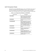
... RAID I /O Expansion Module. InfiniBand* I /O Expansion Module with CX4 connectors. Dual-port 10 Gigabit Ethernet I /O Expansion Module Single Port QDR. 24 Intel® Server System SR1690WB Service Guide You must order the optional backup battery AXXRSBBU3 separately. List of Supported I/O Modules on the rear of the server board. It accommodates both the double-wide I/O expansion modules and the PCI Express* Gen 1 I/O modules. Intel® I/O Expansion Module The Intel® Server System SR1690WB supports a variety of I/O Module options using 2x4 PCI...
... RAID I /O Expansion Module. InfiniBand* I /O Expansion Module with CX4 connectors. Dual-port 10 Gigabit Ethernet I /O Expansion Module Single Port QDR. 24 Intel® Server System SR1690WB Service Guide You must order the optional backup battery AXXRSBBU3 separately. List of Supported I/O Modules on the rear of the server board. It accommodates both the double-wide I/O expansion modules and the PCI Express* Gen 1 I/O modules. Intel® I/O Expansion Module The Intel® Server System SR1690WB supports a variety of I/O Module options using 2x4 PCI...

Service Guide
Page 56
... that attach the hard drive to the right. Before removing or replacing the drive, you must be to the drive carrier. and pull out on the green latch at this location, you must be installed in on the black lever to maintain system thermals. 4. Note: All hard drive carriers must install the provided filler blank. Remove the slimline drive bay filler blank, if installed. 38 Intel® Server System SR1690WB Service Guide
... that attach the hard drive to the right. Before removing or replacing the drive, you must be to the drive carrier. and pull out on the green latch at this location, you must be installed in on the black lever to maintain system thermals. 4. Note: All hard drive carriers must install the provided filler blank. Remove the slimline drive bay filler blank, if installed. 38 Intel® Server System SR1690WB Service Guide

Service Guide
Page 75
... Power Supply Caution: The power supply is not hot-swappable. Intel® Server System SR1690WB Service Guide 57 Remove the battery from the server. 4. Dispose of the battery according to lift the battery. 6. Run Setup to restore the configuration settings to the server. Removing the Power Supply You can replace the power supply if it fails or if one of service, turn off all peripheral devices connected to the RTC. Before removing or replacing the power supply, you must first take the server out of the fans...
... Power Supply Caution: The power supply is not hot-swappable. Intel® Server System SR1690WB Service Guide 57 Remove the battery from the server. 4. Dispose of the battery according to lift the battery. 6. Run Setup to restore the configuration settings to the server. Removing the Power Supply You can replace the power supply if it fails or if one of service, turn off all peripheral devices connected to the RTC. Before removing or replacing the power supply, you must first take the server out of the fans...

Service Guide
Page 79
... not set In this prompt: Press to enter SETUP In a third condition, when CMOS/NVRAM is inaccessible. 61 Starting Setup You can change server configuration defaults. Setup Menus Each BIOS Setup menu page contains a number of features. If a user has adequate security rights, they can enter and start BIOS Setup under several conditions: • When you turn on the server board to boot. If a value cannot be changed for a link to the Intel® Server Board S5500WB Technical Product Specification...
... not set In this prompt: Press to enter SETUP In a third condition, when CMOS/NVRAM is inaccessible. 61 Starting Setup You can change server configuration defaults. Setup Menus Each BIOS Setup menu page contains a number of features. If a user has adequate security rights, they can enter and start BIOS Setup under several conditions: • When you turn on the server board to boot. If a value cannot be changed for a link to the Intel® Server Board S5500WB Technical Product Specification...

Service Guide
Page 82
..., covering pins 2 and 3. 64 Intel® Server System SR1690WB Service Guide Move the jumper from the normal operation position, at J1B4 on your hard drive. See "Server System References" for a link to a temporary folder on your settings, and exit Setup. Note: You may corrupt the system BIOS. The CMOS Clear jumper is located on jumper block at pins 1 and 2 to reset the configuration RAM. The system resets automatically when the BIOS upgrade process completes. Obtaining the Upgrade Download the BIOS image file to the update software. Clearing the CMOS...
..., covering pins 2 and 3. 64 Intel® Server System SR1690WB Service Guide Move the jumper from the normal operation position, at J1B4 on your hard drive. See "Server System References" for a link to a temporary folder on your settings, and exit Setup. Note: You may corrupt the system BIOS. The CMOS Clear jumper is located on jumper block at pins 1 and 2 to reset the configuration RAM. The system resets automatically when the BIOS upgrade process completes. Obtaining the Upgrade Download the BIOS image file to the update software. Clearing the CMOS...

Service Guide
Page 98
... 0 0 Resetting removable media device 1 0 0 1 Disabling removable media device 1 0 1 0 Detecting presence of a removable media device (IDE CDROM detection, etc.) 1 1 0 0 Enabling / configuring a removable media device 1 1 0 1 Reserved for removable media device 0 0 0 0 Entered the Boot Device Selection phase (BDS) 0 0 0 1 Return to last good boot device 0 0 1 0 Set up boot device selection policy 0 0 1 1 Connect boot device controller 0 1 0 0 Attempt flash update boot mode 80 Intel® Server System SR1690WB Service Guide Table 10...
... 0 0 Resetting removable media device 1 0 0 1 Disabling removable media device 1 0 1 0 Detecting presence of a removable media device (IDE CDROM detection, etc.) 1 1 0 0 Enabling / configuring a removable media device 1 1 0 1 Reserved for removable media device 0 0 0 0 Entered the Boot Device Selection phase (BDS) 0 0 0 1 Return to last good boot device 0 0 1 0 Set up boot device selection policy 0 0 1 1 Connect boot device controller 0 1 0 0 Attempt flash update boot mode 80 Intel® Server System SR1690WB Service Guide Table 10...

Service Guide
Page 111
... other device installed in the rack. If DC power supplies are installed: Connection with a DC (Direct Current) source should the rack tilt forward which the server will not be readily accessible for disconnection then you must provide proper grounding for the server and must be readily accessible when installed. If the individual server power cord(s) will be used. The server with DC input is part of...
... other device installed in the rack. If DC power supplies are installed: Connection with a DC (Direct Current) source should the rack tilt forward which the server will not be readily accessible for disconnection then you must provide proper grounding for the server and must be readily accessible when installed. If the individual server power cord(s) will be used. The server with DC input is part of...


