Service Guide
Page 4
...; Four CPU Heatsinks • One unit Rack Bracket • Screws for Intel products, see http://support.intel.com/support/motherboards/server/SR1680MV/compat.htm. Product Contents, Order Options, and Accessories Your Intel® Server System SR1680MV ships with your Intel server product. For information about which accessories, memory, processors, and third-party hardware were tested and can obtain software updates and...
...; Four CPU Heatsinks • One unit Rack Bracket • Screws for Intel products, see http://support.intel.com/support/motherboards/server/SR1680MV/compat.htm. Product Contents, Order Options, and Accessories Your Intel® Server System SR1680MV ships with your Intel server product. For information about which accessories, memory, processors, and third-party hardware were tested and can obtain software updates and...
Service Guide
Page 5
... updates To make sure your system falls within the allowed power budget Use this webpage, type the document or software name in the product box Spares and Configuration Guide Tested Hardware Operating Systems List Supported Processors List Supported Memory List Driver (for operating system drivers) Firmware Update Package Power Budget Tool Intel® Server System SR1680MV Service Guide v
... updates To make sure your system falls within the allowed power budget Use this webpage, type the document or software name in the product box Spares and Configuration Guide Tested Hardware Operating Systems List Supported Processors List Supported Memory List Driver (for operating system drivers) Firmware Update Package Power Budget Tool Intel® Server System SR1680MV Service Guide v

Service Guide
Page 11
...é ...vii Instrucciones de seguridad importantes vii Warnings ...ix Chapter 1: Server System Features 1 System Overview ...3 Server Chassis Layout 3 Front View Components 4 Back View Components 4 Buttons and System LEDs ...5 Front Panel Buttons and LEDs 5 Rear Panel Button and LEDs...Processor 13 Installing the Processor 15 Removing the Heatsink 16 Installing the Heatsink 17 System Memory ...17 System Memory Channel Population Requirements for Memory RAS Modes 19 Independent Channel Mode 19 Mirrored Channel Mode 19 Lockstep Channel Mode 19 Intel® Server System SR1680MV...
...é ...vii Instrucciones de seguridad importantes vii Warnings ...ix Chapter 1: Server System Features 1 System Overview ...3 Server Chassis Layout 3 Front View Components 4 Back View Components 4 Buttons and System LEDs ...5 Front Panel Buttons and LEDs 5 Rear Panel Button and LEDs...Processor 13 Installing the Processor 15 Removing the Heatsink 16 Installing the Heatsink 17 System Memory ...17 System Memory Channel Population Requirements for Memory RAS Modes 19 Independent Channel Mode 19 Mirrored Channel Mode 19 Lockstep Channel Mode 19 Intel® Server System SR1680MV...

Service Guide
Page 17
... Location 23 Figure 23. Front Panel Buttons and LEDs of Processors 12 Figure 11. Unplugging the Power Cord 11 Figure 9. Location of Server 5 Figure 6. Opening the Load Plate 13 Figure 12. Lifting the Processor Out of the Socket 21 Figure 20. Lifting the DIMM ...Closing the Load Plate 15 Figure 15. DIMM Socket Location 18 Figure 19. Power Supply Location 27 Figure 30. Intel® Server System SR1680MV with 2.5-inch Pluggable HDDs 4 Figure 4. Lift a System Fan Up from I /O Board Cage Module Location 25 Figure 27. Left I/O Board Cage Module Location 25 Figure ...
... Location 23 Figure 23. Front Panel Buttons and LEDs of Processors 12 Figure 11. Unplugging the Power Cord 11 Figure 9. Location of Server 5 Figure 6. Opening the Load Plate 13 Figure 12. Lifting the Processor Out of the Socket 21 Figure 20. Lifting the DIMM ...Closing the Load Plate 15 Figure 15. DIMM Socket Location 18 Figure 19. Power Supply Location 27 Figure 30. Intel® Server System SR1680MV with 2.5-inch Pluggable HDDs 4 Figure 4. Lift a System Fan Up from I /O Board Cage Module Location 25 Figure 27. Left I/O Board Cage Module Location 25 Figure ...

Service Guide
Page 19
...Express* Configuration Submenu Fields 80 Table 27. IPMI Configuration Submenu Fields 82 Table 29. View BMC System Event Log Submenu 83 Table 30. Boot Menu of Processor 2 20 Table 5. Security Menu Fields 92 Table 40. CPU Configuration Submenu 65 Table 11. CPU...15. Security Menu of Tables Table 1. List of BIOS Setup Utility 91 Table 39. Intel® Server System SR1680MV Feature Summary 2 Table 2. Advanced Menu of BIOS Setup Utility 95 Intel® Server System SR1680MV Service Guide xix Removable Drives Submenu 89 Table 37. USB Configuration Submenu Fields 76 Table...
...Express* Configuration Submenu Fields 80 Table 27. IPMI Configuration Submenu Fields 82 Table 29. View BMC System Event Log Submenu 83 Table 30. Boot Menu of Processor 2 20 Table 5. Security Menu Fields 92 Table 40. CPU Configuration Submenu 65 Table 11. CPU...15. Security Menu of Tables Table 1. List of BIOS Setup Utility 91 Table 39. Intel® Server System SR1680MV Feature Summary 2 Table 2. Advanced Menu of BIOS Setup Utility 95 Intel® Server System SR1680MV Service Guide xix Removable Drives Submenu 89 Table 37. USB Configuration Submenu Fields 76 Table...

Service Guide
Page 21
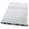
... are based on the Intel® 5500 chipset platform, each server board uses high-performance, dual processors of the server system is installed. Based on one I/O board. You can accelerate even the most complicated server tasks. Two I/O boards...system. Intel® Server System SR1680MV with different placement. This chapter provides a photograph of the product, list of the server system features, and diagrams showing the location of the Intel® Server System SR1680MV. The corresponding I /O boards. Intel® Server System SR1680MV Service Guide 1 Two server...
... are based on the Intel® 5500 chipset platform, each server board uses high-performance, dual processors of the server system is installed. Based on one I/O board. You can accelerate even the most complicated server tasks. Two I/O boards...system. Intel® Server System SR1680MV with different placement. This chapter provides a photograph of the product, list of the server system features, and diagrams showing the location of the Intel® Server System SR1680MV. The corresponding I /O boards. Intel® Server System SR1680MV Service Guide 1 Two server...
Service Guide
Page 22
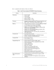
... up to 32 shared GPIO ports • Supports Programmable Wake-up to four Intel® Xeon® Processor 5500 Series and Intel® Xeon® 5600 Series (two per server node) • Three channels per processor; Table 1. Intel® Server System SR1680MV Feature Summary Feature Dimensions Processor Memory On-board LAN On-board VGA Integrated Super I /O board to support a...; Support for BMC support • Fully Functional Serial Port, compatible with the external RTC interface • One PCI-E x8 slot on each riser connector 2 Intel® Server System SR1680MV Service Guide
... up to 32 shared GPIO ports • Supports Programmable Wake-up to four Intel® Xeon® Processor 5500 Series and Intel® Xeon® 5600 Series (two per server node) • Three channels per processor; Table 1. Intel® Server System SR1680MV Feature Summary Feature Dimensions Processor Memory On-board LAN On-board VGA Integrated Super I /O board to support a...; Support for BMC support • Fully Functional Serial Port, compatible with the external RTC interface • One PCI-E x8 slot on each riser connector 2 Intel® Server System SR1680MV Service Guide
Service Guide
Page 29
...processor and memory DIMMs, and PCI-E add-in this server is also designed with your reference. The locking tab, retaining clip and so forth provide the convenient method to remove or install the components without any tools. The tool-less components are mainly for adding and replacing system...) screwdriver (#1 bit and #2 bit) • Needle nosed pliers • Antistatic wrist strap and conductive foam pad (recommended) Intel® Server System SR1680MV Service Guide 9 In addition, this chapter are listed: • Motherboard Cage Modules • I/O Board Cage Modules • ...
...processor and memory DIMMs, and PCI-E add-in this server is also designed with your reference. The locking tab, retaining clip and so forth provide the convenient method to remove or install the components without any tools. The tool-less components are mainly for adding and replacing system...) screwdriver (#1 bit and #2 bit) • Needle nosed pliers • Antistatic wrist strap and conductive foam pad (recommended) Intel® Server System SR1680MV Service Guide 9 In addition, this chapter are listed: • Motherboard Cage Modules • I/O Board Cage Modules • ...

Service Guide
Page 32
or dual-processor system. Processor 1 2. Processor 2 12 Intel® Server System SR1680MV Service Guide The following figure shows the location of Processors 1. Figure 9. Removing the Mid-Top Cover Central Processing Unit (CPU) Each installed server node provides two surface mount LGA 1366 CPU sockets designed for the Intel® Xeon® Processor 5500 series and Intel® Xeon® Processor 5600 series. One server node can be configured to either a single- Location of processors on the motherboard: Figure 10.
or dual-processor system. Processor 1 2. Processor 2 12 Intel® Server System SR1680MV Service Guide The following figure shows the location of Processors 1. Figure 9. Removing the Mid-Top Cover Central Processing Unit (CPU) Each installed server node provides two surface mount LGA 1366 CPU sockets designed for the Intel® Xeon® Processor 5500 series and Intel® Xeon® Processor 5600 series. One server node can be configured to either a single- Location of processors on the motherboard: Figure 10.

Service Guide
Page 33
.... Unlock the load lever and lift it is not turned on the processor 1 socket. You can install single or dual processors on the motherboard according to Figure 10. 2. Intel® Server System SR1680MV Service Guide 13 To power off the server, see "Mid-Top Cover". Make sure the server is recommended that you remove or install the heatsink...
.... Unlock the load lever and lift it is not turned on the processor 1 socket. You can install single or dual processors on the motherboard according to Figure 10. 2. Intel® Server System SR1680MV Service Guide 13 To power off the server, see "Mid-Top Cover". Make sure the server is recommended that you remove or install the heatsink...

Service Guide
Page 34
Placing on the PnP Cap 14 Intel® Server System SR1680MV Service Guide Figure 13. Place the PnP cap onto the load plate. Figure 12. Lifting the Processor Out of the Socket 4.
Placing on the PnP Cap 14 Intel® Server System SR1680MV Service Guide Figure 13. Place the PnP cap onto the load plate. Figure 12. Lifting the Processor Out of the Socket 4.

Service Guide
Page 35
Lock the load lever. Closing the Load Plate Installing the Processor Reverse the steps in "Removing the Processor" to install the processor. However, when inserting the processor into the socket, make sure the golden corner on the processor is pointed toward the socket. Figure 14. Close the load plate. 6. Intel® Server System SR1680MV Service Guide 15 5.
Lock the load lever. Closing the Load Plate Installing the Processor Reverse the steps in "Removing the Processor" to install the processor. However, when inserting the processor into the socket, make sure the golden corner on the processor is pointed toward the socket. Figure 14. Close the load plate. 6. Intel® Server System SR1680MV Service Guide 15 5.

Service Guide
Page 36
... it is locked. Lift the heatsink up from the installed processor. 16 Intel® Server System SR1680MV Service Guide Figure 15. Pointing the Golden Corner Toward the Socket Note: When the processor is in one orientation. Do not force the processor into the socket to secure the processor. Loosen the two securing screws. 2. The lever clicks on the...
... it is locked. Lift the heatsink up from the installed processor. 16 Intel® Server System SR1680MV Service Guide Figure 15. Pointing the Golden Corner Toward the Socket Note: When the processor is in one orientation. Do not force the processor into the socket to secure the processor. Loosen the two securing screws. 2. The lever clicks on the...

Service Guide
Page 37
...Removing the Heatsink Installing the Heatsink Reverse the steps in a server environment. Mixed memory is neither tested nor supported. System Memory Each motherboard supports 18 DDR3 1333/1066/800 DIMMs depending on the bottom of the installed processor, do not forget to check if the grease is not ...recommended for use in "Removing the Heatsink" to 72GB memory when 8GB DIMM is shown in the right direction-you should see the heatsink information when you put the heatsink in Figure 17: Intel® Server System SR1680MV ...
...Removing the Heatsink Installing the Heatsink Reverse the steps in a server environment. Mixed memory is neither tested nor supported. System Memory Each motherboard supports 18 DDR3 1333/1066/800 DIMMs depending on the bottom of the installed processor, do not forget to check if the grease is not ...recommended for use in "Removing the Heatsink" to 72GB memory when 8GB DIMM is shown in the right direction-you should see the heatsink information when you put the heatsink in Figure 17: Intel® Server System SR1680MV ...

Service Guide
Page 38
DIMM Socket Location 18 Intel® Server System SR1680MV Service Guide Location of 18 DIMM sockets is respectively shown in Figure 18. Figure 18. Figure 17. The DIMM sequence of System Memories There are 18 DIMMs on the motherboard to support processor 1 and processor 2.
DIMM Socket Location 18 Intel® Server System SR1680MV Service Guide Location of 18 DIMM sockets is respectively shown in Figure 18. Figure 18. Figure 17. The DIMM sequence of System Memories There are 18 DIMMs on the motherboard to support processor 1 and processor 2.

Service Guide
Page 39
... the same DIMM slot location across Channel 0 and Channel 1 must hold the same DIMM type with regards to the system is half of processor 1 and 2. DIMM slot populations within a channel do not have to be identical but individual channels may be populated ...identically with regards to size and organization. Independent Channel Mode Channels can be populated in this mode. Channel 2 is populated. Intel® Server System SR1680MV Service Guide 19 Lockstep Channel Mode requires that the same slot positions across Channel 0 and Channel 1 must be populated the same...
... the same DIMM slot location across Channel 0 and Channel 1 must hold the same DIMM type with regards to the system is half of processor 1 and 2. DIMM slot populations within a channel do not have to be identical but individual channels may be populated ...identically with regards to size and organization. Independent Channel Mode Channels can be populated in this mode. Channel 2 is populated. Intel® Server System SR1680MV Service Guide 19 Lockstep Channel Mode requires that the same slot positions across Channel 0 and Channel 1 must be populated the same...

Service Guide
Page 40
...- V V - Ideal DIMM Installation Options for each CPU so as to insert DIMM equally for D-F Channels of Processor 1 DIMM A3 A2 A1 B3 B2 B1 C3 C2 C1 1 - - V 6 - V 5 - V ...Intel® Server System SR1680MV Service Guide V - - V - - VV - V - - It is marked as "-" and installed DIMM socket is recommended to give maximizes system performance. For Unbuffered DIMMs or Quad-rank Registered DIMMs, only configuration 1~6 could be used within one motherboard. Table 3. Ideal DIMM Installation Options for A-C Channels of Processor...
...- V V - Ideal DIMM Installation Options for each CPU so as to insert DIMM equally for D-F Channels of Processor 1 DIMM A3 A2 A1 B3 B2 B1 C3 C2 C1 1 - - V 6 - V 5 - V ...Intel® Server System SR1680MV Service Guide V - - V - - VV - V - - It is marked as "-" and installed DIMM socket is recommended to give maximizes system performance. For Unbuffered DIMMs or Quad-rank Registered DIMMs, only configuration 1~6 could be used within one motherboard. Table 3. Ideal DIMM Installation Options for A-C Channels of Processor...

Service Guide
Page 67
... Connector (J29) 7. SATA Power Connector (J47) 6. MISC Jumper Intel® Server System SR1680MV Service Guide 47 Server board Power Connector2 (J3) 14. 4 Connectors, Jumpers, and LEDs Connector and Component Locations of Server Board 1. Processor 1 (CPU 1) 9. Server board IO Connector (J1) 13. Connectors and Component Locations of Server Board Figure 54. Server board SATA3 Connector (J31) 8. DIMM Socket Group 2 (J17, J18...
... Connector (J29) 7. SATA Power Connector (J47) 6. MISC Jumper Intel® Server System SR1680MV Service Guide 47 Server board Power Connector2 (J3) 14. 4 Connectors, Jumpers, and LEDs Connector and Component Locations of Server Board 1. Processor 1 (CPU 1) 9. Server board IO Connector (J1) 13. Connectors and Component Locations of Server Board Figure 54. Server board SATA3 Connector (J31) 8. DIMM Socket Group 2 (J17, J18...

Service Guide
Page 83
... Intel® Server System SR1680MV Service Guide 63 Use [+] or [-] to select a field. Select Screen Select Item + - Main Menu of BIOS Setup Utility BIOS Setup Utility Main Advanced Boot Security Exit System Overview AMIBIOS Version :08.00.15 Build Date :02/16/09 ID :MARBLE VALLEY105 Processor Intel(R)... Xeon(R) CPU E5540 @ 2.53 GHz Speed :2533 MHz Count :2 System Memory Size :6144 MB System Time [09:52:34] System Date [Fri 11/14/2008] Use [ENTER], [TAB], or [SHIFT-TAB] to configure system Time. Use [+] or [-] to configure system Time. Change...
... Intel® Server System SR1680MV Service Guide 63 Use [+] or [-] to select a field. Select Screen Select Item + - Main Menu of BIOS Setup Utility BIOS Setup Utility Main Advanced Boot Security Exit System Overview AMIBIOS Version :08.00.15 Build Date :02/16/09 ID :MARBLE VALLEY105 Processor Intel(R)... Xeon(R) CPU E5540 @ 2.53 GHz Speed :2533 MHz Count :2 System Memory Size :6144 MB System Time [09:52:34] System Date [Fri 11/14/2008] Use [ENTER], [TAB], or [SHIFT-TAB] to configure system Time. Use [+] or [-] to configure system Time. Change...

Service Guide
Page 85
...] Execute-Disable Bit Capacity [Enabled] Active Processor Cores [All] Intel® SpeedStep(tm) tech [Enabled] Intel® C-STATE tech [Disabled] For UP platforms, leave it may use to tune performance to full-speed. (if supported by all components). Table 11. Intel® Server System SR1680MV Service Guide 65 For DP/MP servers, it enabled. Table 10. Select Screen...
...] Execute-Disable Bit Capacity [Enabled] Active Processor Cores [All] Intel® SpeedStep(tm) tech [Enabled] Intel® C-STATE tech [Disabled] For UP platforms, leave it may use to tune performance to full-speed. (if supported by all components). Table 11. Intel® Server System SR1680MV Service Guide 65 For DP/MP servers, it enabled. Table 10. Select Screen...