Service Guide
Page 3
... board features, a list of the product, and product diagrams to add and replace components on the cable connection. In this book, you may need, troubleshooting information, and instructions on how to help you for detailed information on adding and replacing components. Use this chapter for purchasing and using the Intel® Server System SR1680MV. Chapter 5 describes the update process and configure features of the embedded SATA RAID options and how to racks. Intel® Server System SR1680MV Service Guide...
... board features, a list of the product, and product diagrams to add and replace components on the cable connection. In this book, you may need, troubleshooting information, and instructions on how to help you for detailed information on adding and replacing components. Use this chapter for purchasing and using the Intel® Server System SR1680MV. Chapter 5 describes the update process and configure features of the embedded SATA RAID options and how to racks. Intel® Server System SR1680MV Service Guide...
Service Guide
Page 5
..., adapter cards, and so forth) and operating systems that were tested with this product Processors that were tested with this product DIMMs that were tested with this product For drivers For firmware and BIOS updates To make sure your system falls within the allowed power budget Use this webpage, type the document or software name in the product box Spares and Configuration Guide Tested Hardware Operating Systems List Supported Processors List Supported Memory List Driver (for operating system drivers) Firmware Update Package Power Budget Tool Intel® Server System SR1680MV Service...
..., adapter cards, and so forth) and operating systems that were tested with this product Processors that were tested with this product DIMMs that were tested with this product For drivers For firmware and BIOS updates To make sure your system falls within the allowed power budget Use this webpage, type the document or software name in the product box Spares and Configuration Guide Tested Hardware Operating Systems List Supported Processors List Supported Memory List Driver (for operating system drivers) Firmware Update Package Power Budget Tool Intel® Server System SR1680MV Service...
Service Guide
Page 9
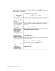
... to the safety instructions. Intel® Server System SR1680MV Service Guide ix We recommend that slips over any unpainted metal surface on power, telephone, and communication cables. After removing a board from its protective wrapper or from system, you open the chassis, add, or remove any other regulatory approvals of other products / components will most likely result in this guide to remove a jumper, or you are using needle nosed pliers...
... to the safety instructions. Intel® Server System SR1680MV Service Guide ix We recommend that slips over any unpainted metal surface on power, telephone, and communication cables. After removing a board from its protective wrapper or from system, you open the chassis, add, or remove any other regulatory approvals of other products / components will most likely result in this guide to remove a jumper, or you are using needle nosed pliers...

Service Guide
Page 12
... Installing a 2.5-inch Pluggable SATA HDD Backplane 33 System Fans ...33 Removing a System Fan 34 Installing a System Fan 35 Air Duct ...35 Removing the IOB Air Duct 35 Installing Air Ducts ...36 PCI-E Cage ...36 Removing a PCI-E Cage 36 Installing a PCI-E Cage 38 Daughter Cards (Optional 38 Removing the IO Expansion Module 39 Installing the IO Expansion Module 41 Chapter 3: Cable Connections 43 Connectors and Pin 1 Locations 43 Cable Connections ...44 Chapter 4: Connectors, Jumpers, and LEDs 47 Connector and Component Locations of Server Board 47 Connector and Component Locations...
... Installing a 2.5-inch Pluggable SATA HDD Backplane 33 System Fans ...33 Removing a System Fan 34 Installing a System Fan 35 Air Duct ...35 Removing the IOB Air Duct 35 Installing Air Ducts ...36 PCI-E Cage ...36 Removing a PCI-E Cage 36 Installing a PCI-E Cage 38 Daughter Cards (Optional 38 Removing the IO Expansion Module 39 Installing the IO Expansion Module 41 Chapter 3: Cable Connections 43 Connectors and Pin 1 Locations 43 Cable Connections ...44 Chapter 4: Connectors, Jumpers, and LEDs 47 Connector and Component Locations of Server Board 47 Connector and Component Locations...
Service Guide
Page 13
... Remote Access Configuration Submenu 84 Boot Menu ...85 Boot Setting Configuration Submenu 86 Boot Device Priority Submenu 88 Removable Drives Submenu 89 CD/DVD Drives Submenu 90 Security Menu ...91 Trusted Computing Submenu 93 Exit Menu ...95 BIOS Updates ...96 ROM Flash ...96 Chapter 6: Embedded SATA RAID 99 Enabling RAID in the BIOS Setup 99 Chapter 7: Installing the Rackmount Rail Kits 101 Procedure to install the rail kit 102 Appendix A: Intel® Server Issue Report Form 105 Appendix B: Troubleshooting 111 Resetting the System...
... Remote Access Configuration Submenu 84 Boot Menu ...85 Boot Setting Configuration Submenu 86 Boot Device Priority Submenu 88 Removable Drives Submenu 89 CD/DVD Drives Submenu 90 Security Menu ...91 Trusted Computing Submenu 93 Exit Menu ...95 BIOS Updates ...96 ROM Flash ...96 Chapter 6: Embedded SATA RAID 99 Enabling RAID in the BIOS Setup 99 Chapter 7: Installing the Rackmount Rail Kits 101 Procedure to install the rail kit 102 Appendix A: Intel® Server Issue Report Form 105 Appendix B: Troubleshooting 111 Resetting the System...

Service Guide
Page 19
... 73 Table 19. USB Configuration Submenu 76 Table 22. PCI Express* Configuration Submenu Fields 80 Table 27. Boot Setting Configuration Submenu Fields 86 Table 35. CD/DVD Drives Submenu 90 Table 38. Super IO Chipset Submenu 74 Table 20. CPU Configuration Submenu Fields 65 Table 12. List of BIOS Setup Utility 86 Table 34. Ideal DIMM Installation Options for D-F Channels of BIOS Setup Utility 95 Intel® Server System SR1680MV Service Guide xix Boot Setting Configuration Submenu of Tables...
... 73 Table 19. USB Configuration Submenu 76 Table 22. PCI Express* Configuration Submenu Fields 80 Table 27. Boot Setting Configuration Submenu Fields 86 Table 35. CD/DVD Drives Submenu 90 Table 38. Super IO Chipset Submenu 74 Table 20. CPU Configuration Submenu Fields 65 Table 12. List of BIOS Setup Utility 86 Table 34. Ideal DIMM Installation Options for D-F Channels of BIOS Setup Utility 95 Intel® Server System SR1680MV Service Guide xix Boot Setting Configuration Submenu of Tables...
Service Guide
Page 22
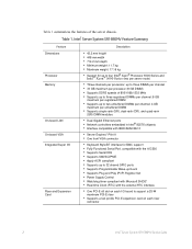
... • Supports Serial IRQ • Supports SMI/SCI/PME • Apply ACPI compliant • Supports up to 32 shared GPIO ports • Supports Programmable Wake-up to two unbuffered DIMMs per channel; 4 GB maximum per processor; Intel® Server System SR1680MV Feature Summary Feature Dimensions Processor Memory On-board LAN On-board VGA Integrated Super I /O board to support a 25-W maximum PCI-E riser • Supports a low-profile PCI-E expansion card on each riser connector 2 Intel® Server System SR1680MV Service Guide Table 1.
... • Supports Serial IRQ • Supports SMI/SCI/PME • Apply ACPI compliant • Supports up to 32 shared GPIO ports • Supports Programmable Wake-up to two unbuffered DIMMs per channel; 4 GB maximum per processor; Intel® Server System SR1680MV Feature Summary Feature Dimensions Processor Memory On-board LAN On-board VGA Integrated Super I /O board to support a 25-W maximum PCI-E riser • Supports a low-profile PCI-E expansion card on each riser connector 2 Intel® Server System SR1680MV Service Guide Table 1.

Service Guide
Page 48
... the location of the power distribution board. Power Distribution Board Note: Before you remove or install the power distribution board, complete the following steps: 1. To power off the server, see "Power Off". 28 Intel® Server System SR1680MV Service Guide Make sure the server is not turned on the server chassis. Figure 30. Figure 31. Removing the Power Supply Module Installing the Power Supply Module Reverse the "Removing the Power Supply Module" steps to the AC power. Power Distribution Board This section introduces the replacement...
... the location of the power distribution board. Power Distribution Board Note: Before you remove or install the power distribution board, complete the following steps: 1. To power off the server, see "Power Off". 28 Intel® Server System SR1680MV Service Guide Make sure the server is not turned on the server chassis. Figure 30. Figure 31. Removing the Power Supply Module Installing the Power Supply Module Reverse the "Removing the Power Supply Module" steps to the AC power. Power Distribution Board This section introduces the replacement...
Service Guide
Page 79
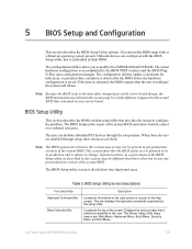
... to change. The BIOS Setup utility screen is the most often changed part of the server board design, the BIOS information described in this section may be a little different compared to modify the CMOS RAM and NVRAM. This bar displays the keyboard commands supported by the BIOS POST routines and the BIOS PlugN-Play auto-configuration manager. Note: The BIOS options described in your server board. Intel® Server System SR1680MV Service Guide 59 5 BIOS Setup and Configuration This section describes the BIOS Setup Utility options...
... to change. The BIOS Setup utility screen is the most often changed part of the server board design, the BIOS information described in this section may be a little different compared to modify the CMOS RAM and NVRAM. This bar displays the keyboard commands supported by the BIOS POST routines and the BIOS PlugN-Play auto-configuration manager. Note: The BIOS options described in your server board. Intel® Server System SR1680MV Service Guide 59 5 BIOS Setup and Configuration This section describes the BIOS Setup Utility options...

Service Guide
Page 80
.... If an option cannot be entered. Each menu contains a set of configurable options and/or informational fields. When Setup is prompted to use the Del function key to enter Setup as follows: Press to navigate through the Setup utility. BIOS Setup Utility Screen Descriptions Functional Area Description Options Menu Each Option Menu occupies the left and center sections of security in the parent menu. 60 Intel® Server System SR1680MV Service Guide The Keyboard Command Bar supports the following: Key Enter Table 6. These...
.... If an option cannot be entered. Each menu contains a set of configurable options and/or informational fields. When Setup is prompted to use the Del function key to enter Setup as follows: Press to navigate through the Setup utility. BIOS Setup Utility Screen Descriptions Functional Area Description Options Menu Each Option Menu occupies the left and center sections of security in the parent menu. 60 Intel® Server System SR1680MV Service Guide The Keyboard Command Bar supports the following: Key Enter Table 6. These...

Service Guide
Page 93
... device supports it . Auto: The Data transfer from and to the device occurs one sector at a time if the device supports it and the device is not already formatted with LBA Mode disabled. Enable/Disable 32-bit Data Transfer. Select DMA Mode. stands for Self-Monitoring, Analysis and Reporting Technology. Intel® Server System SR1680MV Service Guide 73 Table 18. S.M.A.R.T. Disabled: The Data transfer from and to a power failure. Select PIO Mode...
... device supports it . Auto: The Data transfer from and to the device occurs one sector at a time if the device supports it and the device is not already formatted with LBA Mode disabled. Enable/Disable 32-bit Data Transfer. Select DMA Mode. stands for Self-Monitoring, Analysis and Reporting Technology. Intel® Server System SR1680MV Service Guide 73 Table 18. S.M.A.R.T. Disabled: The Data transfer from and to a power failure. Select PIO Mode...
Service Guide
Page 111
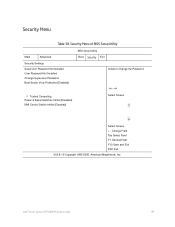
... General Help F10 Save and Exit ESC Exit V02.61 © Copyright 1985-2006, American Megatrends, Inc. Security Menu Table 38. Intel® Server System SR1680MV Service Guide 91 Security Menu of BIOS Setup Utility Main Advanced Security Settings Supervisor Password Not Installed User Password Not Installed Change Supervisor Password Boot Sector Virus Protection [Disabled] BIOS Setup Utility Boot Security Exit Install or Change the Password. • Trusted Computing Power & Reset Switches Inhibit [Disabled] NMI Control Switch Inhibit [Disabled] Select Screen Select Screen + -
... General Help F10 Save and Exit ESC Exit V02.61 © Copyright 1985-2006, American Megatrends, Inc. Security Menu Table 38. Intel® Server System SR1680MV Service Guide 91 Security Menu of BIOS Setup Utility Main Advanced Security Settings Supervisor Password Not Installed User Password Not Installed Change Supervisor Password Boot Sector Virus Protection [Disabled] BIOS Setup Utility Boot Security Exit Install or Change the Password. • Trusted Computing Power & Reset Switches Inhibit [Disabled] NMI Control Switch Inhibit [Disabled] Select Screen Select Screen + -

Service Guide
Page 119
...; SR1680MV server is embedded the Intel® Matrix Storage Manager with support for RAID levels 0, 1 and with drivers to support Microsoft Windows* operating systems. Enabling RAID in the BIOS setup as option to [RAID]. 4. Set the Configure SATA AS as described in the following procedure: 1. 6 Embedded SATA RAID This section provides an overview of the SATA Software RAID options embedded on the server board. To enable this feature, you must set an option in the BIOS Setup By default, the BIOS does NOT enable RAID support. Intel® Server System SR1680MV Service Guide 99...
...; SR1680MV server is embedded the Intel® Matrix Storage Manager with support for RAID levels 0, 1 and with drivers to support Microsoft Windows* operating systems. Enabling RAID in the BIOS setup as option to [RAID]. 4. Set the Configure SATA AS as described in the following procedure: 1. 6 Embedded SATA RAID This section provides an overview of the SATA Software RAID options embedded on the server board. To enable this feature, you must set an option in the BIOS Setup By default, the BIOS does NOT enable RAID support. Intel® Server System SR1680MV Service Guide 99...
Service Guide
Page 131
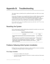
... source. Hardware failure is a less frequent cause. For any drivers used for a link to perform reset your system using the system. If you cannot resolve your server problems on . Table 46. Firmware upgrades include updates for assistance. Resetting the System Before going through in ? Resetting the System To do this Soft boot reset to the "Intel® Server Issue Report Form" for BIOS, and the baseboard management controller (BMC). Intel® Server System SR1680MV Service Guide 111 Appendix B: Troubleshooting This chapter...
... source. Hardware failure is a less frequent cause. For any drivers used for a link to perform reset your system using the system. If you cannot resolve your server problems on . Table 46. Firmware upgrades include updates for assistance. Resetting the System Before going through in ? Resetting the System To do this Soft boot reset to the "Intel® Server Issue Report Form" for BIOS, and the baseboard management controller (BMC). Intel® Server System SR1680MV Service Guide 111 Appendix B: Troubleshooting This chapter...

Service Guide
Page 132
... any external peripheral devices. Make sure your video display monitor). 112 Intel® Server System SR1680MV Service Guide If applicable, ensure that comes with your video display monitor and keyboard are no conflicts-for the keyboard and the video monitor. 2. Hardware Diagnostic Testing This section provides a more detailed approach to the system and/or the peripheral devices. 1. Failure to do so can cause permanent damage to identifying a hardware problem and locating its brightness and contrast controls to the tested component lists...
... any external peripheral devices. Make sure your video display monitor). 112 Intel® Server System SR1680MV Service Guide If applicable, ensure that comes with your video display monitor and keyboard are no conflicts-for the keyboard and the video monitor. 2. Hardware Diagnostic Testing This section provides a more detailed approach to the system and/or the peripheral devices. 1. Failure to do so can cause permanent damage to identifying a hardware problem and locating its brightness and contrast controls to the tested component lists...

Service Guide
Page 133
... or the cable from the hard disk drive, make sure there is checked, its activity light should turn on briefly? If you securely plugged the server AC power cord into the power supply? • Remove all add-in the system. If the operating system prompt does not appear, see if the system boots. If so, the power LED might be loose. • Have you cannot correct the problem, contact your service representative or...
... or the cable from the hard disk drive, make sure there is checked, its activity light should turn on briefly? If you securely plugged the server AC power cord into the power supply? • Remove all add-in the system. If the operating system prompt does not appear, see if the system boots. If so, the power LED might be loose. • Have you cannot correct the problem, contact your service representative or...

Service Guide
Page 135
...? • Are the fan power connectors properly connected to the server board? • Are the power supply cables properly connected to the current drivers. • Make sure the driver is loaded and the protocols are using the correct and the current drivers. If not, see "Power Light Does Not Light". • Are any shorted wires caused by pinched-cables or have power connector plugs been forced into power connector sockets the wrong way? Intel® Server System SR1680MV Service Guide 115
...? • Are the fan power connectors properly connected to the server board? • Are the power supply cables properly connected to the current drivers. • Make sure the driver is loaded and the protocols are using the correct and the current drivers. If not, see "Power Light Does Not Light". • Are any shorted wires caused by pinched-cables or have power connector plugs been forced into power connector sockets the wrong way? Intel® Server System SR1680MV Service Guide 115
Service Guide
Page 136
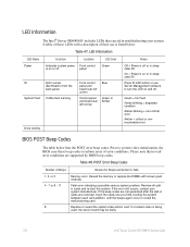
... Front control panel and board rear left corner Control panel and board rear left corner Blue Green or Amber Drive Activity Notes Off = Power is off or in sleep state S5 On = Power is on or in sleep stats S0 Press ID LED button or use is being used, the server board may be faulty. 116 Intel® Server System SR1680MV Service Guide Prior to turn the LED on -board video is listed below lists the POST error beep codes. Reseat the memory or replace the...
... Front control panel and board rear left corner Control panel and board rear left corner Blue Green or Amber Drive Activity Notes Off = Power is off or in sleep state S5 On = Power is on or in sleep stats S0 Press ID LED button or use is being used, the server board may be faulty. 116 Intel® Server System SR1680MV Service Guide Prior to turn the LED on -board video is listed below lists the POST error beep codes. Reseat the memory or replace the...

Service Guide
Page 140
... a site that is: • Clean and free of used batteries according to access the power supply cord(s), because they serve as the product's main power disconnect. 120 Intel® Server System SR1680MV Service Guide To install the covers: 1. Insert and lock the padlock to the system to operate in place can remove the system covers. The system is incorrectly replaced. Unlock and remove the padlock from strong electromagnetic fields produced by the equipment...
... a site that is: • Clean and free of used batteries according to access the power supply cord(s), because they serve as the product's main power disconnect. 120 Intel® Server System SR1680MV Service Guide To install the covers: 1. Insert and lock the padlock to the system to operate in place can remove the system covers. The system is incorrectly replaced. Unlock and remove the padlock from strong electromagnetic fields produced by the equipment...

Service Guide
Page 186
... have certification marks 166 Intel® Server System SR1680MV Service Guide If the power system for the equipment rack is not the exact type required. This mains disconnect must be readily accessible, and it . The branch circuit protection shall be UL (Underwriters Laboratories, Inc.) Listed/CSA (Canadian Standards Organization) Certified type SJT, 18-3 AWG (American Wire Gauge). If the DC power system for the equipment...
... have certification marks 166 Intel® Server System SR1680MV Service Guide If the power system for the equipment rack is not the exact type required. This mains disconnect must be readily accessible, and it . The branch circuit protection shall be UL (Underwriters Laboratories, Inc.) Listed/CSA (Canadian Standards Organization) Certified type SJT, 18-3 AWG (American Wire Gauge). If the DC power system for the equipment...


