
Service Guide
Page 1
Intel® Server System SR1680MV Service Guide A Guide for Technically Qualified Assemblers of Intel® Identified Subassemblies/Products Intel Order Number E74835-005
Intel® Server System SR1680MV Service Guide A Guide for Technically Qualified Assemblers of Intel® Identified Subassemblies/Products Intel Order Number E74835-005
Service Guide
Page 2
... used outside any patent, copyright or other countries. * Other names and brands may occur. All Rights Reserved ii Intel® Server System SR1680MV Service Guide Intel's own chassis are not designed, intended or authorized for use Intel developed server building blocks to consult vendor datasheets and operating parameters to use in any time, without notice. Disclaimer Information...
... used outside any patent, copyright or other countries. * Other names and brands may occur. All Rights Reserved ii Intel® Server System SR1680MV Service Guide Intel's own chassis are not designed, intended or authorized for use Intel developed server building blocks to consult vendor datasheets and operating parameters to use in any time, without notice. Disclaimer Information...
Service Guide
Page 3
...Intel® Server System SR1680MV. For the latest version of the Intel® Server System SR1680MV. In this chapter, you identify components and their locations. Use this manual, see http://support.intel.com/support/motherboards/server/SR1680MV/. Chapter 2 provides instructions on the cable connection. Use this server system. Chapter 4 provides the description of the functions of the system BIOS. Intel® Server System SR1680MV...components you for purchasing and using the Intel® Server System SR1680MV. Chapter 7 provides instructions for detailed ...
...Intel® Server System SR1680MV. For the latest version of the Intel® Server System SR1680MV. In this chapter, you identify components and their locations. Use this manual, see http://support.intel.com/support/motherboards/server/SR1680MV/. Chapter 2 provides instructions on the cable connection. Use this server system. Chapter 4 provides the description of the functions of the system BIOS. Intel® Server System SR1680MV...components you for purchasing and using the Intel® Server System SR1680MV. Chapter 7 provides instructions for detailed ...
Service Guide
Page 4
... HDD • One 1100-W power supply In addition, you may need or want to purchase one or more of the following Intel website: http://support.intel.com/support/motherboards/server/SR1680MV/ iv Intel® Server System SR1680MV Service Guide For information about which accessories, memory, processors, and third-party hardware were tested and can obtain software updates and...
... HDD • One 1100-W power supply In addition, you may need or want to purchase one or more of the following Intel website: http://support.intel.com/support/motherboards/server/SR1680MV/ iv Intel® Server System SR1680MV Service Guide For information about which accessories, memory, processors, and third-party hardware were tested and can obtain software updates and...
Service Guide
Page 5
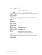
... Document or Software Intel® Server System SR1680MV Technical Product Specification Intel® Server System SR1680MV Quick Start User's Guide in the search field at the left side of the screen and select the option to install it Accessories or other Intel server products Hardware (peripheral... Memory List Driver (for an extensive list of drivers available) Operating System Driver (for operating system drivers) Firmware Update Package Power Budget Tool Intel® Server System SR1680MV Service Guide v Additional Information and Software For this information or software For...
... Document or Software Intel® Server System SR1680MV Technical Product Specification Intel® Server System SR1680MV Quick Start User's Guide in the search field at the left side of the screen and select the option to install it Accessories or other Intel server products Hardware (peripheral... Memory List Driver (for an extensive list of drivers available) Operating System Driver (for operating system drivers) Firmware Update Package Power Budget Tool Intel® Server System SR1680MV Service Guide v Additional Information and Software For this information or software For...

Service Guide
Page 7
.... See also Intel Server Boards and Server Chassis Safety Information on the Intel® Server Resource CD and/or at http://support.intel.com/support/motherboards/ server/sb/cs-010770.htm. Instrucciones de seguridad importantes Lea todas las declaraciones de seguridad y precaución de este documento antes de realizar cualquiera de las instrucciones. Intel® Server System SR1680MV Service Guide vii...
.... See also Intel Server Boards and Server Chassis Safety Information on the Intel® Server Resource CD and/or at http://support.intel.com/support/motherboards/ server/sb/cs-010770.htm. Instrucciones de seguridad importantes Lea todas las declaraciones de seguridad y precaución de este documento antes de realizar cualquiera de las instrucciones. Intel® Server System SR1680MV Service Guide vii...
Service Guide
Page 9
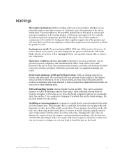
...workstation. ESD and handling boards: Always handle boards carefully. If your jumpers do not have a small tab on the board. Intel® Server System SR1680MV Service Guide ix Hazardous conditions, devices and cables: Hazardous electrical conditions may bend or break the pins on top that jumper. ...the wide sides can be present on /off: The power button DOES NOT turn off the server and disconnect the power cord, telecommunications systems, networks, and modems attached to the server before you perform all procedures in which the product is sold. Some jumpers have such a ...
...workstation. ESD and handling boards: Always handle boards carefully. If your jumpers do not have a small tab on the board. Intel® Server System SR1680MV Service Guide ix Hazardous conditions, devices and cables: Hazardous electrical conditions may bend or break the pins on top that jumper. ...the wide sides can be present on /off: The power button DOES NOT turn off the server and disconnect the power cord, telecommunications systems, networks, and modems attached to the server before you perform all procedures in which the product is sold. Some jumpers have such a ...

Service Guide
Page 11
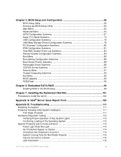
...de sécurité ...vii Instrucciones de seguridad importantes vii Warnings ...ix Chapter 1: Server System Features 1 System Overview ...3 Server Chassis Layout 3 Front View Components 4 Back View Components 4 Buttons and System LEDs ...5 Front Panel Buttons and LEDs 5 Rear Panel Button and LEDs 6 LED ... Removing the Heatsink 16 Installing the Heatsink 17 System Memory ...17 System Memory Channel Population Requirements for Memory RAS Modes 19 Independent Channel Mode 19 Mirrored Channel Mode 19 Lockstep Channel Mode 19 Intel® Server System SR1680MV Service Guide xi
...de sécurité ...vii Instrucciones de seguridad importantes vii Warnings ...ix Chapter 1: Server System Features 1 System Overview ...3 Server Chassis Layout 3 Front View Components 4 Back View Components 4 Buttons and System LEDs ...5 Front Panel Buttons and LEDs 5 Rear Panel Button and LEDs 6 LED ... Removing the Heatsink 16 Installing the Heatsink 17 System Memory ...17 System Memory Channel Population Requirements for Memory RAS Modes 19 Independent Channel Mode 19 Mirrored Channel Mode 19 Lockstep Channel Mode 19 Intel® Server System SR1680MV Service Guide xi

Service Guide
Page 12
... HDD Backplane 32 Removing an HDD Backplane 33 Installing a 2.5-inch Pluggable SATA HDD Backplane 33 System Fans ...33 Removing a System Fan 34 Installing a System Fan 35 Air Duct ...35 Removing the IOB Air Duct 35 Installing Air Ducts ...36 PCI...Locations 43 Cable Connections ...44 Chapter 4: Connectors, Jumpers, and LEDs 47 Connector and Component Locations of Server Board 47 Connector and Component Locations of IO Board 49 Connector and Component Locations of NIC Board 50 Connectors... Connectors and Component Locations of PDB 55 xii Intel® Server System SR1680MV Service Guide
... HDD Backplane 32 Removing an HDD Backplane 33 Installing a 2.5-inch Pluggable SATA HDD Backplane 33 System Fans ...33 Removing a System Fan 34 Installing a System Fan 35 Air Duct ...35 Removing the IOB Air Duct 35 Installing Air Ducts ...36 PCI...Locations 43 Cable Connections ...44 Chapter 4: Connectors, Jumpers, and LEDs 47 Connector and Component Locations of Server Board 47 Connector and Component Locations of IO Board 49 Connector and Component Locations of NIC Board 50 Connectors... Connectors and Component Locations of PDB 55 xii Intel® Server System SR1680MV Service Guide
Service Guide
Page 13
...to install the rail kit 102 Appendix A: Intel® Server Issue Report Form 105 Appendix B: Troubleshooting 111 Resetting the System ...111 Problems following Initial System Installation 111 First Steps Checklist 111 Hardware ...System Lights 113 Confirming Loading of the Operating System 113 Specific Problems and Corrective Actions 113 Power Light Does Not Light 113 No Characters Appear on Screen 114 Characters Are Distorted or Incorrect 114 System Cooling Fans Do Not Rotate Properly 115 Cannot Connect to a Server 115 LED Information ...116 Intel® Server System SR1680MV...
...to install the rail kit 102 Appendix A: Intel® Server Issue Report Form 105 Appendix B: Troubleshooting 111 Resetting the System ...111 Problems following Initial System Installation 111 First Steps Checklist 111 Hardware ...System Lights 113 Confirming Loading of the Operating System 113 Specific Problems and Corrective Actions 113 Power Light Does Not Light 113 No Characters Appear on Screen 114 Characters Are Distorted or Incorrect 114 System Cooling Fans Do Not Rotate Properly 115 Cannot Connect to a Server 115 LED Information ...116 Intel® Server System SR1680MV...

Service Guide
Page 17
... 33. 2.5-inch Pluggable SATA HDD Location 30 Figure 34. Lift a System Fan Up from I /O Board Cage Module Location 25 Figure 26. PCI-E Cage Location 36 Intel® Server System SR1680MV Service Guide xvii Layout of Server Chassis with 2.5-inch Pluggable SATA HDD Location 23 Figure 23. Pressing the...Figure 16. Lifting the DIMM Out of Processors 12 Figure 11. Remove the Screws and Lift the Backplane Up 33 Figure 39. Intel® Server System SR1680MV with 2.5-inch Pluggable HDDs 4 Figure 4. Removing the Mid-Top Cover 12 Figure 10. Location of the Socket 21 Figure 20....
... 33. 2.5-inch Pluggable SATA HDD Location 30 Figure 34. Lift a System Fan Up from I /O Board Cage Module Location 25 Figure 26. PCI-E Cage Location 36 Intel® Server System SR1680MV Service Guide xvii Layout of Server Chassis with 2.5-inch Pluggable SATA HDD Location 23 Figure 23. Pressing the...Figure 16. Lifting the DIMM Out of Processors 12 Figure 11. Remove the Screws and Lift the Backplane Up 33 Figure 39. Intel® Server System SR1680MV with 2.5-inch Pluggable HDDs 4 Figure 4. Removing the Mid-Top Cover 12 Figure 10. Location of the Socket 21 Figure 20....

Service Guide
Page 18
... PCI Cage from the I /O Board 44 Figure 53. Connectors and Components of MISC Jumper 56 Figure 63. Secure The Server Ears To Racks 104 xviii Intel® Server System SR1680MV Service Guide Securing the Slot Cover 38 Figure 46. Connecting the System Fan Cables 45 Figure 54. Location of InfiniBand Card 53 Figure 60. Push The...
... PCI Cage from the I /O Board 44 Figure 53. Connectors and Components of MISC Jumper 56 Figure 63. Secure The Server Ears To Racks 104 xviii Intel® Server System SR1680MV Service Guide Securing the Slot Cover 38 Figure 46. Connecting the System Fan Cables 45 Figure 54. Location of InfiniBand Card 53 Figure 60. Push The...

Service Guide
Page 19
Intel® Server System SR1680MV Feature Summary 2 Table 2. Ideal DIMM Installation Options for A-C Channels of Processor 1 20 Table 4. BIOS Setup Utility Screen Descriptions 59 Table 6. CPU Configuration Submenu 65 Table ... 72 Table 18. IPMI Configuration Submenu Fields 82 Table 29. Boot Device Priority Submenu 88 Table 36. Security Menu of BIOS Setup Utility 95 Intel® Server System SR1680MV Service Guide xix Exit Menu of BIOS Setup Utility 91 Table 39. Main Menu of BIOS Setup Utility 85 Table 33. SATA Configuration Submenu1 67...
Intel® Server System SR1680MV Feature Summary 2 Table 2. Ideal DIMM Installation Options for A-C Channels of Processor 1 20 Table 4. BIOS Setup Utility Screen Descriptions 59 Table 6. CPU Configuration Submenu 65 Table ... 72 Table 18. IPMI Configuration Submenu Fields 82 Table 29. Boot Device Priority Submenu 88 Table 36. Security Menu of BIOS Setup Utility 95 Intel® Server System SR1680MV Service Guide xix Exit Menu of BIOS Setup Utility 91 Table 39. Main Menu of BIOS Setup Utility 85 Table 33. SATA Configuration Submenu1 67...

Service Guide
Page 20
Product Regulatory Compliance Markings 160 xx Intel® Server System SR1680MV Service Guide Recommended screwdrivers 101 Table 45. POST Error Beep Codes 116 Table 49. Error Beep Codes Generated by Intel® Management Module 117 Table 50. BIOS Requirements Description 96 Table 44. Resetting the System 111 Table 47. LED Information ...116 Table 48. Location and Adapt Depth for Racks 102 Table 46. Table 43.
Product Regulatory Compliance Markings 160 xx Intel® Server System SR1680MV Service Guide Recommended screwdrivers 101 Table 45. POST Error Beep Codes 116 Table 49. Error Beep Codes Generated by Intel® Management Module 117 Table 50. BIOS Requirements Description 96 Table 44. Resetting the System 111 Table 47. LED Information ...116 Table 48. Location and Adapt Depth for Racks 102 Table 46. Table 43.

Service Guide
Page 21
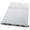
... I /O board must be fixed to the server board when powering on the system. Intel® Server System SR1680MV Service Guide 1 Based on the server system. Note: The minimum configuration of important components and connections on the Intel® 5500 chipset platform, each server board uses high-performance, dual processors of the Intel® Server System SR1680MV. Figure 1. Two server boards can only access the power...
... I /O board must be fixed to the server board when powering on the system. Intel® Server System SR1680MV Service Guide 1 Based on the server system. Note: The minimum configuration of important components and connections on the Intel® 5500 chipset platform, each server board uses high-performance, dual processors of the Intel® Server System SR1680MV. Figure 1. Two server boards can only access the power...
Service Guide
Page 22
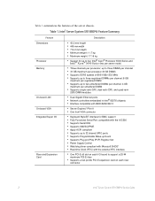
... 8 GB maximum per registered DIMM • Supports up to two unbuffered DIMMs per channel; 4 GB maximum per processor; Intel® Server System SR1680MV Feature Summary Feature Dimensions Processor Memory On-board LAN On-board VGA Integrated Super I /O board to four... Intel® Xeon® Processor 5500 Series and Intel® Xeon® 5600 Series (two per server node) • Three channels per unbuffered DIMM • Supports single-rank (SR), dual...
... 8 GB maximum per registered DIMM • Supports up to two unbuffered DIMMs per channel; 4 GB maximum per processor; Intel® Server System SR1680MV Feature Summary Feature Dimensions Processor Memory On-board LAN On-board VGA Integrated Super I /O board to four... Intel® Xeon® Processor 5500 Series and Intel® Xeon® 5600 Series (two per server node) • Three channels per unbuffered DIMM • Supports single-rank (SR), dual...

Service Guide
Page 23
I /O Card or InfiniBand* Card (optional) Figure 2. Server boards 7. Pluggable HDD Bays 9. System Fans 5. Pluggable HDD Backplane 8. Power Supply 2. GB I /O Boards 3. System Overview Server Chassis Layout 1. Layout of Server Chassis with 2.5-inch Pluggable HDDs Intel® Server System SR1680MV Service Guide 3 Power Distribution Board 6. NIC Card 10. PCI-E Cage 4.
I /O Card or InfiniBand* Card (optional) Figure 2. Server boards 7. Pluggable HDD Bays 9. System Fans 5. Pluggable HDD Backplane 8. Power Supply 2. GB I /O Boards 3. System Overview Server Chassis Layout 1. Layout of Server Chassis with 2.5-inch Pluggable HDDs Intel® Server System SR1680MV Service Guide 3 Power Distribution Board 6. NIC Card 10. PCI-E Cage 4.

Service Guide
Page 24
... front view of both internal and external devices are located on the front. Front View of both internal and external devices. 4 Intel® Server System SR1680MV Service Guide Some connectors, buttons, and system LEDs of Server with 2.5-inch pluggable HDDs: 1. VGA Port 2. HDD LED 12. 2.5-inch Pluggable HDDs Figure 3. The following introduces the front view of...
... front view of both internal and external devices are located on the front. Front View of both internal and external devices. 4 Intel® Server System SR1680MV Service Guide Some connectors, buttons, and system LEDs of Server with 2.5-inch pluggable HDDs: 1. VGA Port 2. HDD LED 12. 2.5-inch Pluggable HDDs Figure 3. The following introduces the front view of...

Service Guide
Page 25
... panel. Rear NIC2 Ports 5. NIC LED 2. UID LED 6. The front panel status LEDs allow constant monitoring of Server Intel® Server System SR1680MV Service Guide 5 System Health LED 3. These LEDs provide visual cues to the status of NIC link, system health, UID (unique identifier), and power. Rear UID LEDs 6. Rear UID Buttons Figure 4. The following figures shows...
... panel. Rear NIC2 Ports 5. NIC LED 2. UID LED 6. The front panel status LEDs allow constant monitoring of Server Intel® Server System SR1680MV Service Guide 5 System Health LED 3. These LEDs provide visual cues to the status of NIC link, system health, UID (unique identifier), and power. Rear UID LEDs 6. Rear UID Buttons Figure 4. The following figures shows...

Service Guide
Page 26
... LEDs 5. LED Information Feature Power LED Table 2. Off: No AC power to the system. 6 Intel® Server System SR1680MV Service Guide Back View LEDs and Buttons of the two I /O Boards The following table provides detailed LED information. Front View LEDs On: System has AC power but in standby mode. The back view LEDs and buttons information...
... LEDs 5. LED Information Feature Power LED Table 2. Off: No AC power to the system. 6 Intel® Server System SR1680MV Service Guide Back View LEDs and Buttons of the two I /O Boards The following table provides detailed LED information. Front View LEDs On: System has AC power but in standby mode. The back view LEDs and buttons information...

