
Service Guide
Page 1
Intel® Server System SR1670HV Service Guide Intel Part Number: E74138-004 A Guide for Technically Qualified Assemblers of Intel® Identified Subassemblies/Products
Intel® Server System SR1670HV Service Guide Intel Part Number: E74138-004 A Guide for Technically Qualified Assemblers of Intel® Identified Subassemblies/Products

Service Guide
Page 2
Disclaimer Disclaimer ® Information in this document. All Rights Reserved ii Intel® Server System SR1670HV Service Guide It is the responsibility of the system integrator that chooses not to use Intel developed server building blocks to consult vendor datasheets and operating parameters to determine the amount of high-density VLSI and power delivery components that need adequate...
Disclaimer Disclaimer ® Information in this document. All Rights Reserved ii Intel® Server System SR1670HV Service Guide It is the responsibility of the system integrator that chooses not to use Intel developed server building blocks to consult vendor datasheets and operating parameters to determine the amount of high-density VLSI and power delivery components that need adequate...
Service Guide
Page 4
... 7 provides an overview of the embedded SATA RAID options and how to the following Intel web site: http://support.intel.com/support/motherboards/server/SR1670HV/ Manual Organization Chapter 1 provides a brief overview of this server system. For the latest version of the Intel® Server System SR1670HV. This document provides a brief overview of the features of the board/chassis, a list of...
... 7 provides an overview of the embedded SATA RAID options and how to the following Intel web site: http://support.intel.com/support/motherboards/server/SR1670HV/ Manual Organization Chapter 1 provides a brief overview of this server system. For the latest version of the Intel® Server System SR1670HV. This document provides a brief overview of the features of the board/chassis, a list of...

Service Guide
Page 5
...* Embedded MegaRAID Software Users Manual Spares and Configuration Guide Tested Hardware and Operating System List Supported Processors Supported Memory Driver (for operating system drivers) Firmware Update Intel® Server System SR1670HV Service Guide v Preface Additional Information and Software Documentation and software for this server product are available on this Web page, type the document or software name...
...* Embedded MegaRAID Software Users Manual Spares and Configuration Guide Tested Hardware and Operating System List Supported Processors Supported Memory Driver (for operating system drivers) Firmware Update Intel® Server System SR1670HV Service Guide v Preface Additional Information and Software Documentation and software for this server product are available on this Web page, type the document or software name...

Service Guide
Page 6
... 5.1 Configuration and Support Jumpers 35 5.1.1 5.1.2 5.1.3 5.1.4 Clear RTC RAM (CLRTC1 35 VGA Controller Setting (3-pin VGA_SW1 36 DDR3 Voltage Control Setting (4-pin LVDDR3_SEL1, LVDDR3_SEL2) ...... 36 LAN Controller Setting (3-poin LAN_SW1, LAN_SW2 37 vi Intel® Server System SR1670HV Service Guide System Service 28 4.1 Replacing Power Supply Units (PSUs 28 4.2 Replacing System Fans 29 4.3 SATA/SAS BackPlane Replacement 30...
... 5.1 Configuration and Support Jumpers 35 5.1.1 5.1.2 5.1.3 5.1.4 Clear RTC RAM (CLRTC1 35 VGA Controller Setting (3-pin VGA_SW1 36 DDR3 Voltage Control Setting (4-pin LVDDR3_SEL1, LVDDR3_SEL2) ...... 36 LAN Controller Setting (3-poin LAN_SW1, LAN_SW2 37 vi Intel® Server System SR1670HV Service Guide System Service 28 4.1 Replacing Power Supply Units (PSUs 28 4.2 Replacing System Fans 29 4.3 SATA/SAS BackPlane Replacement 30...

Service Guide
Page 7
... Applications and Utilities Installation 105 8.5.1 Running the Resource CD 105 8.5.2 Drivers Menu 105 8.5.3 Utilities Menu 106 8.5.4 Make Disk Menu 106 Intel® Server System SR1670HV Service Guide vii BIOS Updates and Configuration 47 6.1 Updating System BIOS 47 6.2 BIOS Recovery Process 48 6.3 BIOS Setup Utility ...49 6.3.1 Accessing BIOS Setup Utility 50 6.3.2 BIOS Setup Features and Navigation...
... Applications and Utilities Installation 105 8.5.1 Running the Resource CD 105 8.5.2 Drivers Menu 105 8.5.3 Utilities Menu 106 8.5.4 Make Disk Menu 106 Intel® Server System SR1670HV Service Guide vii BIOS Updates and Configuration 47 6.1 Updating System BIOS 47 6.2 BIOS Recovery Process 48 6.3 BIOS Setup Utility ...49 6.3.1 Accessing BIOS Setup Utility 50 6.3.2 BIOS Setup Features and Navigation...

Service Guide
Page 10
...Mounting Ear ...27 Figure 42. CPU Notch and Alignment Key 12 Figure 16. Removing the Screw from Slot Bay 20 Figure 26. Server Management LAN Port 22 Figure 31. Disconnecting System Fan Cable 29 Figure 46. Back Panel 3 Figure 3. HDD Status LED...7 Figure 8. Applying Thermal Paste 12 Figure 17. Installing the...to 1U Space on Rack 27 Figure 41. Positioning the Rack Rail to Fit 21 Figure 28. Inserting Fan Into the Fan Cage 29 x Intel® Server System SR1670HV Service Guide DIMM Notch...19 Figure 24. List of Figures List of Chassis 26 Figure 38. Lifting...
...Mounting Ear ...27 Figure 42. CPU Notch and Alignment Key 12 Figure 16. Removing the Screw from Slot Bay 20 Figure 26. Server Management LAN Port 22 Figure 31. Disconnecting System Fan Cable 29 Figure 46. Back Panel 3 Figure 3. HDD Status LED...7 Figure 8. Applying Thermal Paste 12 Figure 17. Installing the...to 1U Space on Rack 27 Figure 41. Positioning the Rack Rail to Fit 21 Figure 28. Inserting Fan Into the Fan Cage 29 x Intel® Server System SR1670HV Service Guide DIMM Notch...19 Figure 24. List of Figures List of Chassis 26 Figure 38. Lifting...

Service Guide
Page 11
Sliding the Hard Disk Drive Bay Module 30 Figure 51. Cable Bundles in DOS 48 Figure 80. Clear RTC RAM...35 Figure 60. Intel® ICH10R SATA Port SW RAID Setting 38 Figure 64. SATA Connectors ...39 Figure 66. Standby Power LED 45 Figure 76. Updating... 82. Pop-Up Window...51 Figure 83. AHCI Configuration Menu 55 Figure 87. System Memory Information Menu 56 Figure 90. Chipset Configuration Menu 61 Figure 94. South Bridge Chipset Configuration Menu 64 Intel® Server System SR1670HV Service Guide xi Control Panel Module Screw 33 Figure 57 ...34 Figure 58 Detached ...
Sliding the Hard Disk Drive Bay Module 30 Figure 51. Cable Bundles in DOS 48 Figure 80. Clear RTC RAM...35 Figure 60. Intel® ICH10R SATA Port SW RAID Setting 38 Figure 64. SATA Connectors ...39 Figure 66. Standby Power LED 45 Figure 76. Updating... 82. Pop-Up Window...51 Figure 83. AHCI Configuration Menu 55 Figure 87. System Memory Information Menu 56 Figure 90. Chipset Configuration Menu 61 Figure 94. South Bridge Chipset Configuration Menu 64 Intel® Server System SR1670HV Service Guide xi Control Panel Module Screw 33 Figure 57 ...34 Figure 58 Detached ...
Service Guide
Page 12
...Virtual Drives (Selection) Pulldown Menu 88 Figure 132. Create RAID Volume Menu 91 Figure 137. Intel ICH8R/ICH9R/ICH10R/DO SATA RAID Controller Item 96 Figure 145. Driver Disk Source 97 xii Intel® Server System SR1670HV Service Guide PCIPnP Configuration Menu 67 Figure 102. Exit Menu...80 Figure 119. Virtual Drive Menu ...84 Figure 123. Selecting the Configurable Array on Easy Configuration Menu 85 Figure 125. Create Volume Warning Message 92 Figure 139. Microsoft Windows Server* Setup Menu 94 Figure 142. Intel VT-d Configuration Menu 65 Figure 99.
...Virtual Drives (Selection) Pulldown Menu 88 Figure 132. Create RAID Volume Menu 91 Figure 137. Intel ICH8R/ICH9R/ICH10R/DO SATA RAID Controller Item 96 Figure 145. Driver Disk Source 97 xii Intel® Server System SR1670HV Service Guide PCIPnP Configuration Menu 67 Figure 102. Exit Menu...80 Figure 119. Virtual Drive Menu ...84 Figure 123. Selecting the Configurable Array on Easy Configuration Menu 85 Figure 125. Create Volume Warning Message 92 Figure 139. Microsoft Windows Server* Setup Menu 94 Figure 142. Intel VT-d Configuration Menu 65 Figure 99.

Service Guide
Page 13
... the Installation 103 Figure 165. Utilities Menu ...106 Figure 171. Make Disk Menu ...106 Intel® Server System SR1670HV Service Guide xiii Screen 97 Figure 150. License Agreement Terms 102 Figure 163. Selecting the SuSe* Installation 98 Figure 151. Intel® Chipset Device Software Window 100 Figure 156. Setup Complete Window 101 Figure 159. Installation...
... the Installation 103 Figure 165. Utilities Menu ...106 Figure 171. Make Disk Menu ...106 Intel® Server System SR1670HV Service Guide xiii Screen 97 Figure 150. License Agreement Terms 102 Figure 163. Selecting the SuSe* Installation 98 Figure 151. Intel® Chipset Device Software Window 100 Figure 156. Setup Complete Window 101 Figure 159. Installation...

Service Guide
Page 14
System Feature Set ...1 Table 3. RJ-45 Ports 1 and 2 LEDs Descriptions 7 Table 6. Maximum Memory Allocation Using RDIMMs 16 Table 8. Supported RDIMM Configurations 17 Table 9. List of Tables List of Tables Table 1. HDD LED Status Definitions 7 Table 7. Memory Population Table 18 xiv Intel® Server System SR1670HV Service Guide Supported UDIMM Configurations 17 Table 10. System Package Contents List 1 Table 2. Server Node Connectors and Components Descriptions 6 Table 4. Front Panel LEDs Descriptions 6 Table 5.
System Feature Set ...1 Table 3. RJ-45 Ports 1 and 2 LEDs Descriptions 7 Table 6. Maximum Memory Allocation Using RDIMMs 16 Table 8. Supported RDIMM Configurations 17 Table 9. List of Tables List of Tables Table 1. HDD LED Status Definitions 7 Table 7. Memory Population Table 18 xiv Intel® Server System SR1670HV Service Guide Supported UDIMM Configurations 17 Table 10. System Package Contents List 1 Table 2. Server Node Connectors and Components Descriptions 6 Table 4. Front Panel LEDs Descriptions 6 Table 5.

Service Guide
Page 15
List of Tables Intel® Server System SR1670HV Service Guide xv
List of Tables Intel® Server System SR1670HV Service Guide xv
Service Guide
Page 16
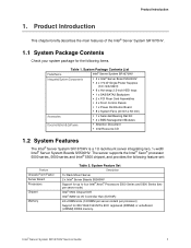
Product Introduction This chapter briefly describes the main features of the Intel® Server System SR1670HV. 1.1 System Package Contents Check your system package for 800/1066/1333 MT/s ECC registered (RDIMM) or unbuffered (UDIMM) DDR3 memory. The server supports the Intel® Xeon® processor 5500 series, 5600 series and Intel® 5500 chipset, and provides the following items. Table...
Product Introduction This chapter briefly describes the main features of the Intel® Server System SR1670HV. 1.1 System Package Contents Check your system package for 800/1066/1333 MT/s ECC registered (RDIMM) or unbuffered (UDIMM) DDR3 memory. The server supports the Intel® Xeon® processor 5500 series, 5600 series and Intel® 5500 chipset, and provides the following items. Table...

Service Guide
Page 17
... cards (one per server node) Video Storage Power Supply Networking Server Management System Dimensions On-board ASPEED* AST2050 with integrated Video Controller ƒ Integrated 2D Video Controller ƒ 8 MB Video Memory 8 x...system's front panel: ƒ Eight 2.5-inch Hot-swap SATA/SAS Hard Drive Bays-four for each installed server node. ƒ Dual independent front control panels-one for each installed server node. ƒ Features found on each front control panel include: System Power and System Reset buttons, LED indicators, and one 2.0 USB port. 2 Intel® Server System SR1670HV...
... cards (one per server node) Video Storage Power Supply Networking Server Management System Dimensions On-board ASPEED* AST2050 with integrated Video Controller ƒ Integrated 2D Video Controller ƒ 8 MB Video Memory 8 x...system's front panel: ƒ Eight 2.5-inch Hot-swap SATA/SAS Hard Drive Bays-four for each installed server node. ƒ Dual independent front control panels-one for each installed server node. ƒ Features found on each front control panel include: System Power and System Reset buttons, LED indicators, and one 2.0 USB port. 2 Intel® Server System SR1670HV...

Service Guide
Page 18
Back Panel 1.5 Internal Features The following features on the server system back panel: ƒ Dual tool-less cold-swap, non-redundant power supplies-one for each installed server node. ƒ Add-in card slot covers for each installed server node. ƒ External I/O ports for each installed server node. Intel® Server System SR1670HV Service Guide 3 Product Introduction System ID LED System ID Button Figure 1. Server System Features 1.4 Rear Panel Features You can find the following figure shows the internal features of the server system. System Features - Figure 2.
Back Panel 1.5 Internal Features The following features on the server system back panel: ƒ Dual tool-less cold-swap, non-redundant power supplies-one for each installed server node. ƒ Add-in card slot covers for each installed server node. ƒ External I/O ports for each installed server node. Intel® Server System SR1670HV Service Guide 3 Product Introduction System ID LED System ID Button Figure 1. Server System Features 1.4 Rear Panel Features You can find the following figure shows the internal features of the server system. System Features - Figure 2.

Service Guide
Page 19
System Component Identification The following figure identifies connectors and major components of each server node. 4 Intel® Server System SR1670HV Service Guide Product Introduction Riser Card Power Supply Modules Riser Card Server Node 1 4 x System Fans Node 1 Server Node 2 Hard Disk Drive Bay Module 4 x System Fans Node 2 Figure 3.
System Component Identification The following figure identifies connectors and major components of each server node. 4 Intel® Server System SR1670HV Service Guide Product Introduction Riser Card Power Supply Modules Riser Card Server Node 1 4 x System Fans Node 1 Server Node 2 Hard Disk Drive Bay Module 4 x System Fans Node 2 Figure 3.

Service Guide
Page 20
Server Node Connectors and Components Intel® Server System SR1670HV Service Guide 5 Product Introduction A B C Q D P O N E M L K F G G H H I I J Figure 4.
Server Node Connectors and Components Intel® Server System SR1670HV Service Guide 5 Product Introduction A B C Q D P O N E M L K F G G H H I I J Figure 4.

Service Guide
Page 21
... no incoming event. BMC reset in progress when re-plug Power cord No LAN connection LAN is present. 6 Intel® Server System SR1670HV Service Guide LGA 1366 Socket N CMOS Battery O Auxilary Front Panel Header P Front Panel Header Q X16 GEN 2 PCI Express* ...Riser Card Slot 1.6 System LED Information 1.6.1 Front Control Panel LEDs LED Power LED HDD Activity Message LED System ID LED LAN LEDs Figure 5. C2) L Peripheral Drive Power ...
... no incoming event. BMC reset in progress when re-plug Power cord No LAN connection LAN is present. 6 Intel® Server System SR1670HV Service Guide LGA 1366 Socket N CMOS Battery O Auxilary Front Panel Header P Front Panel Header Q X16 GEN 2 PCI Express* ...Riser Card Slot 1.6 System LED Information 1.6.1 Front Control Panel LEDs LED Power LED HDD Activity Message LED System ID LED LAN LEDs Figure 5. C2) L Peripheral Drive Power ...

Service Guide
Page 22
...need to disconnect these cables unless you must remove pre-installed components for servicing or to Chapter 4, "System Service" for detailed information on the connections. HDD Status LED Table 6. Refer to install additional devices. Intel® Server System SR1670HV Service Guide 7 RJ-45 Ports 1 and 2 LEDs Descriptions ACT/LINK LED SPEED LED Status Description Status...-in ready but detection error) G/R Blinking RAID rebuilding OFF HDD not found Green Blink Data read/write to HDD 1.7 Cable Connections NOTE: The bundled system cables are pre-connected before shipment.
...need to disconnect these cables unless you must remove pre-installed components for servicing or to Chapter 4, "System Service" for detailed information on the connections. HDD Status LED Table 6. Refer to install additional devices. Intel® Server System SR1670HV Service Guide 7 RJ-45 Ports 1 and 2 LEDs Descriptions ACT/LINK LED SPEED LED Status Description Status...-in ready but detection error) G/R Blinking RAID rebuilding OFF HDD not found Green Blink Data read/write to HDD 1.7 Cable Connections NOTE: The bundled system cables are pre-connected before shipment.

Service Guide
Page 23
USB connector (from server board to front control panel) 5. System Fan connectors (from server board to system fans) 4. Auxiliary Panel connector (from server board to front control panel) 8 Intel® Server System SR1670HV Service Guide SATA connectors (from server board to backplane) 7. Front Control Panel connector (from server board to front control panel) 6. Cable Connections 1.7.1 Pre-Connected System Cables 1. 20-pin Main Power...
USB connector (from server board to front control panel) 5. System Fan connectors (from server board to system fans) 4. Auxiliary Panel connector (from server board to front control panel) 8 Intel® Server System SR1670HV Service Guide SATA connectors (from server board to backplane) 7. Front Control Panel connector (from server board to front control panel) 6. Cable Connections 1.7.1 Pre-Connected System Cables 1. 20-pin Main Power...

