Service Guide
Page 4
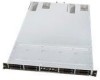
In this server system. Chapter 6 describes the update process and configurable features of the system BIOS Chapter 7 provides an overview of the embedded SATA RAID options and how to follow when replacing common FRUs. Chapter 10 provides Intel Support and Warranty information. iv Intel® Server System SR1670HV Service Guide This manual is written for system technicians who are responsible for troubleshooting, upgrading, and repairing this chapter, you will find a list of the system features, product...
In this server system. Chapter 6 describes the update process and configurable features of the system BIOS Chapter 7 provides an overview of the embedded SATA RAID options and how to follow when replacing common FRUs. Chapter 10 provides Intel Support and Warranty information. iv Intel® Server System SR1670HV Service Guide This manual is written for system technicians who are responsible for troubleshooting, upgrading, and repairing this chapter, you will find a list of the system features, product...

Service Guide
Page 6
... Memory Support 16 2.3.3 Installing a DIMM 18 2.3.4 Removing a DIMM 19 2.4 Installing a PCI Express* Add-In Card to the Server 25 3.2 Attaching the Rack Rails 26 3.3 Rackmounting the Server 27 4. Contents Contents 1. Installing the Rackmount Rail Kit 25 3.1 Attaching the Rails to the Riser Bracket 20 2.5 Installing the BMC Management Module 22 2.6 Hard Disk Drives ...23 3. Jumpers, Connectors, and LEDs 35 5.1 Configuration and Support Jumpers 35 5.1.1 5.1.2 5.1.3 5.1.4 Clear RTC RAM (CLRTC1 35 VGA Controller Setting (3-pin VGA_SW1 36 DDR3 Voltage Control Setting (4-pin...
... Memory Support 16 2.3.3 Installing a DIMM 18 2.3.4 Removing a DIMM 19 2.4 Installing a PCI Express* Add-In Card to the Server 25 3.2 Attaching the Rack Rails 26 3.3 Rackmounting the Server 27 4. Contents Contents 1. Installing the Rackmount Rail Kit 25 3.1 Attaching the Rails to the Riser Bracket 20 2.5 Installing the BMC Management Module 22 2.6 Hard Disk Drives ...23 3. Jumpers, Connectors, and LEDs 35 5.1 Configuration and Support Jumpers 35 5.1.1 5.1.2 5.1.3 5.1.4 Clear RTC RAM (CLRTC1 35 VGA Controller Setting (3-pin VGA_SW1 36 DDR3 Voltage Control Setting (4-pin...

Service Guide
Page 7
... Resource CD 105 8.5.2 Drivers Menu 105 8.5.3 Utilities Menu 106 8.5.4 Make Disk Menu 106 Intel® Server System SR1670HV Service Guide vii Embedded SATA RAID 81 7.1 Selecting a RAID option 81 7.2 Enabling RAID in the BIOS Setup 82 7.3 SATA RAID Setup...82 7.3.1 LSI* Software RAID Configuration Utility 82 7.3.2 Intel® Matrix Storage Manager Configuration Utility 90 8. BIOS Updates and Configuration 47 6.1 Updating System BIOS 47 6.2 BIOS Recovery Process 48 6.3 BIOS Setup Utility ...49 6.3.1 Accessing BIOS Setup Utility 50 6.3.2 BIOS Setup Features and Navigation 50...
... Resource CD 105 8.5.2 Drivers Menu 105 8.5.3 Utilities Menu 106 8.5.4 Make Disk Menu 106 Intel® Server System SR1670HV Service Guide vii Embedded SATA RAID 81 7.1 Selecting a RAID option 81 7.2 Enabling RAID in the BIOS Setup 82 7.3 SATA RAID Setup...82 7.3.1 LSI* Software RAID Configuration Utility 82 7.3.2 Intel® Matrix Storage Manager Configuration Utility 90 8. BIOS Updates and Configuration 47 6.1 Updating System BIOS 47 6.2 BIOS Recovery Process 48 6.3 BIOS Setup Utility ...49 6.3.1 Accessing BIOS Setup Utility 50 6.3.2 BIOS Setup Features and Navigation 50...

Service Guide
Page 11
... Chipset Configuration Menu 61 Figure 95. Restoring the Chassis Cover 30 Figure 49. Front Fan Connectors 40 Figure 68. Peripheral Power Connector (4-pin PWR3 42 Figure 73. Updating the BIOS in the Hard Disk Drive Bay Module 32 Figure 54. Pop-Up Window...51 Figure 83. CPU Bridge Chipset Configuration Menu, Continued 62 Figure 96. South Bridge Chipset Configuration Menu 64 Intel® Server System SR1670HV Service Guide xi Screws On Hard Disk Drive Bay Module 30 Figure 50. SATA Cable Connection...
... Chipset Configuration Menu 61 Figure 95. Restoring the Chassis Cover 30 Figure 49. Front Fan Connectors 40 Figure 68. Peripheral Power Connector (4-pin PWR3 42 Figure 73. Updating the BIOS in the Hard Disk Drive Bay Module 32 Figure 54. Pop-Up Window...51 Figure 83. CPU Bridge Chipset Configuration Menu, Continued 62 Figure 96. South Bridge Chipset Configuration Menu 64 Intel® Server System SR1670HV Service Guide xi Screws On Hard Disk Drive Bay Module 30 Figure 50. SATA Cable Connection...
Service Guide
Page 12
...Intel® Server System SR1670HV Service Guide Legacy Device Configuration Menu 65 Figure 100. ACPI Configuration Menu 71 Figure 108. Advanced ACPI Configuration Menu 72 Figure 109. Security Menu After Supervisor Password is Set 79 Figure 118. Virtual Drive Menu 85 Figure 126. Virtual Drives (Selection) Pulldown Menu 88 Figure 132. Intel® Matrix Storage Manager Configuration Utility 90 Figure 136. USB Configuration Menu 66 Figure 101. RAID Option Jumper Block 81 Figure 120. Hardware Monitor Configuration Menu 70 Figure 105. Hardware Monitor Configuration...
...Intel® Server System SR1670HV Service Guide Legacy Device Configuration Menu 65 Figure 100. ACPI Configuration Menu 71 Figure 108. Advanced ACPI Configuration Menu 72 Figure 109. Security Menu After Supervisor Password is Set 79 Figure 118. Virtual Drive Menu 85 Figure 126. Virtual Drives (Selection) Pulldown Menu 88 Figure 132. Intel® Matrix Storage Manager Configuration Utility 90 Figure 136. USB Configuration Menu 66 Figure 101. RAID Option Jumper Block 81 Figure 120. Hardware Monitor Configuration Menu 70 Figure 105. Hardware Monitor Configuration...

Service Guide
Page 17
... x 1, Rear x 2) ƒ 1 x Internal A-type USB Port ƒ 1 x VGA port Eight 4-pin managed system fan. (Four fans per server node) Add-in Adapter Support 2 x PCI Express* X16 GEN2 slots supporting low-profile half height add-in cards (one per server node) Video Storage Power Supply Networking Server Management System Dimensions On-board ASPEED* AST2050 with integrated Video Controller ƒ Integrated 2D Video Controller ƒ 8 MB Video Memory 8 x 2.5-inch hot-swap SATA Hard Drive Bays (Four drive bays per server node) Embedded support for the following RAID solutions: ƒ Intel®...
... x 1, Rear x 2) ƒ 1 x Internal A-type USB Port ƒ 1 x VGA port Eight 4-pin managed system fan. (Four fans per server node) Add-in Adapter Support 2 x PCI Express* X16 GEN2 slots supporting low-profile half height add-in cards (one per server node) Video Storage Power Supply Networking Server Management System Dimensions On-board ASPEED* AST2050 with integrated Video Controller ƒ Integrated 2D Video Controller ƒ 8 MB Video Memory 8 x 2.5-inch hot-swap SATA Hard Drive Bays (Four drive bays per server node) Embedded support for the following RAID solutions: ƒ Intel®...

Service Guide
Page 21
... Rear I System Fan Connectors J USB(3) 2.0 - 1x5 Pin Header K CPU 1 DIMM Slots (Slots A1- Front Control Panel LEDs Table 4. no incoming event. Normal status Location switch is present. 6 Intel® Server System SR1670HV Service Guide BMC reset in progress when re-plug Power cord No LAN connection LAN is normal; LGA 1366 Socket G Power Supply SMBus - 2x3 Pin Header H Main Power Connector - 20 pin I /O Connectors B BMC Management Module connector C SATA Ports 1-4 D Internal USB(4) 2.0 Port E CPU 2 DIMM Slots (Slots D1 - LGA 1366 Socket N CMOS Battery O Auxilary Front Panel...
... Rear I System Fan Connectors J USB(3) 2.0 - 1x5 Pin Header K CPU 1 DIMM Slots (Slots A1- Front Control Panel LEDs Table 4. no incoming event. Normal status Location switch is present. 6 Intel® Server System SR1670HV Service Guide BMC reset in progress when re-plug Power cord No LAN connection LAN is normal; LGA 1366 Socket G Power Supply SMBus - 2x3 Pin Header H Main Power Connector - 20 pin I /O Connectors B BMC Management Module connector C SATA Ports 1-4 D Internal USB(4) 2.0 Port E CPU 2 DIMM Slots (Slots D1 - LGA 1366 Socket N CMOS Battery O Auxilary Front Panel...

Service Guide
Page 50
... RTC RAM: 1. Turn OFF the computer and unplug the power cord. 2. Plug in CMOS, which includes system setup information such as system passwords. After the CMOS clearance, reinstall the battery. Keep the cap on the CLRTC jumper default position. Removing the cap causes system boot failure! Figure 59. The onboard button cell battery powers the RAM data in the power cord and turn ON the computer. 4. Jumpers, Connectors, and LEDs 5. Jumpers, Connectors, and LEDs 5.1 Configuration and Support Jumpers 5.1.1 Clear RTC RAM (CLRTC1) This jumper allows...
... RTC RAM: 1. Turn OFF the computer and unplug the power cord. 2. Plug in CMOS, which includes system setup information such as system passwords. After the CMOS clearance, reinstall the battery. Keep the cap on the CLRTC jumper default position. Removing the cap causes system boot failure! Figure 59. The onboard button cell battery powers the RAM data in the power cord and turn ON the computer. 4. Jumpers, Connectors, and LEDs 5. Jumpers, Connectors, and LEDs 5.1 Configuration and Support Jumpers 5.1.1 Clear RTC RAM (CLRTC1) This jumper allows...

Service Guide
Page 51
These jumper blocks change the voltage level supplied to the DIMM bank, and should only be updated with full usage information once validation is intended for this server board. 36 Intel® Server System SR1670HV Service Guide Figure 60. Set to pins 1-2 to select 1.5V BIOS control, pins 2-3 to select 1.2V Force or 3-4 to enable or disable the onboard VGA controller. This document will only be supported after Intel has validated their default position may...
These jumper blocks change the voltage level supplied to the DIMM bank, and should only be updated with full usage information once validation is intended for this server board. 36 Intel® Server System SR1670HV Service Guide Figure 60. Set to pins 1-2 to select 1.5V BIOS control, pins 2-3 to select 1.2V Force or 3-4 to enable or disable the onboard VGA controller. This document will only be supported after Intel has validated their default position may...

Service Guide
Page 58
...connector is for the system power button. Intel® Server System SR1670HV Service Guide 43 Jumpers, Connectors, and LEDs Figure 73. The speaker allows you turn on the system power and blinks when the system is in sleep mode. 5.2.9.2 System Message LED (2-pin MLED) This 2-pin connector is for system reboot without turning off mode depending on or puts the system in sleep or soft-off the system power. Connect the chassis power LED cable to this connector. Connect the HDD Activity LED cable to this connector. Pressing the power button turns the system on the BIOS settings...
...connector is for the system power button. Intel® Server System SR1670HV Service Guide 43 Jumpers, Connectors, and LEDs Figure 73. The speaker allows you turn on the system power and blinks when the system is in sleep mode. 5.2.9.2 System Message LED (2-pin MLED) This 2-pin connector is for system reboot without turning off mode depending on or puts the system in sleep or soft-off the system power. Connect the chassis power LED cable to this connector. Connect the HDD Activity LED cable to this connector. Pressing the power button turns the system on the BIOS settings...

Service Guide
Page 62
... web site: http://support.intel.com/support/motherboards/server/SR1670HV/ The System Update or BIOS Update package includes the following procedure to update the BIOS by the AFUDOS utility. ƒ BIOS##.BAT - Intel® Server System SR1670HV Service Guide 47 You can manually set to configure system features and functions to configure the USB Flash Drive as the key is pressed. Extract files from it provides options that you may affect your system after the BIOS Update has completed. See BIOS Setup later in the...
... web site: http://support.intel.com/support/motherboards/server/SR1670HV/ The System Update or BIOS Update package includes the following procedure to update the BIOS by the AFUDOS utility. ƒ BIOS##.BAT - Intel® Server System SR1670HV Service Guide 47 You can manually set to configure system features and functions to configure the USB Flash Drive as the key is pressed. Extract files from it provides options that you may affect your system after the BIOS Update has completed. See BIOS Setup later in the...

Service Guide
Page 64
...BIOS Setup Utility Navigation ƒ BIOS Setup Utility Menu Options Overview CAUTION Intel strongly suggests having only qualified persons with in the USB flash drive and power on the system and access the BIOS Setup utility . 10. Hit the key to its default position. 8. Intel recommends using default BIOS settings whenever possible. Set the Force BIOS Update jumper back to load BIOS Setting Defaults. 11. When the BIOS update has completed successfully, power down the system. 7. Recovering the BIOS Using the Force BIOS Update Jumper 5. Intel® Server System SR1670HV Service Guide...
...BIOS Setup Utility Navigation ƒ BIOS Setup Utility Menu Options Overview CAUTION Intel strongly suggests having only qualified persons with in the USB flash drive and power on the system and access the BIOS Setup utility . 10. Hit the key to its default position. 8. Intel recommends using default BIOS settings whenever possible. Set the Force BIOS Update jumper back to load BIOS Setting Defaults. 11. When the BIOS update has completed successfully, power down the system. 7. Recovering the BIOS Using the Force BIOS Update Jumper 5. Intel® Server System SR1670HV Service Guide...

Service Guide
Page 66
... displays information, options, and sub-menus appropriate to the highlighted Menu Bar option. BIOS Updates and Configuration Server: Provides sub-menus used to view/change IPMI and Remote Connectivity options. Use the up window, allowing you to the preferred settings by a solid blue triangle before each sub-menu field descriptor. Option Fields are for that do not fit on the right side of a menu screen when there are the navigation keys...
... displays information, options, and sub-menus appropriate to the highlighted Menu Bar option. BIOS Updates and Configuration Server: Provides sub-menus used to view/change IPMI and Remote Connectivity options. Use the up window, allowing you to the preferred settings by a solid blue triangle before each sub-menu field descriptor. Option Fields are for that do not fit on the right side of a menu screen when there are the navigation keys...
Service Guide
Page 94
... numbers, then press . 3. Select the Change User Password option and press . 2. Configuration options: [Setup] [Always] Intel® Server System SR1670HV Service Guide 79 Full Access allows viewing and changing all the fields in the Setup utility. 6.3.6.4.3 Change User Password To set , other system security options will display on how to erase the RTC RAM, refer to selected fields, such as Date and Time. BIOS Updates and Configuration NOTE: If you forget your password successfully. Limited allows changes only to the "Configuration and Support Jumpers...
... numbers, then press . 3. Select the Change User Password option and press . 2. Configuration options: [Setup] [Always] Intel® Server System SR1670HV Service Guide 79 Full Access allows viewing and changing all the fields in the Setup utility. 6.3.6.4.3 Change User Password To set , other system security options will display on how to erase the RTC RAM, refer to selected fields, such as Date and Time. BIOS Updates and Configuration NOTE: If you forget your password successfully. Limited allows changes only to the "Configuration and Support Jumpers...

Service Guide
Page 108
... driver disk from the connected SATA drives. Intel® Server System SR1670HV Service Guide 93 8. Driver Installation Driver Installation 8.1 RAID Driver Installation After creating the RAID sets for your changes and exit BIOS Setup. 5. This section provides instructions on to the independent hard disk drive or bootable array. A floppy disk with the LSI* Software RAID configuration utility, the boot priority of RAID driver disk you are now ready to install an operating system to a specified RAID set . Save your server board, you want to create and press to be manually...
... driver disk from the connected SATA drives. Intel® Server System SR1670HV Service Guide 93 8. Driver Installation Driver Installation 8.1 RAID Driver Installation After creating the RAID sets for your changes and exit BIOS Setup. 5. This section provides instructions on to the independent hard disk drive or bootable array. A floppy disk with the LSI* Software RAID configuration utility, the boot priority of RAID driver disk you are now ready to install an operating system to a specified RAID set . Save your server board, you want to create and press to be manually...

Service Guide
Page 109
.... The Windows® Server Operating System Setup starts. Follow screen instructions to create. 4. Decompress the file into the floppy disk drive. 5. Place the Resource CD into the floppy disk drive. 8. When prompted, Press to the floppy disk drive. 2. Driver Installation 7. Locate the RAID driver and place a blank, high-density floppy disk into the optical drive. 3. Insert a blank formatted high-density floppy disk to install a third-party driver. 94 Intel® Server System SR1670HV Service Guide Boot the computer using the Windows® Server installation DVD.
.... The Windows® Server Operating System Setup starts. Follow screen instructions to create. 4. Decompress the file into the floppy disk drive. 5. Place the Resource CD into the floppy disk drive. 8. When prompted, Press to the floppy disk drive. 2. Driver Installation 7. Locate the RAID driver and place a blank, high-density floppy disk into the optical drive. 3. Insert a blank formatted high-density floppy disk to install a third-party driver. 94 Intel® Server System SR1670HV Service Guide Boot the computer using the Windows® Server installation DVD.

Service Guide
Page 110
...icon on -screen instructions to the floppy disk drive, then press . 5. Intel® Server System SR1670HV Service Guide 95 Driver Installation Figure 142. Microsoft Windows* automatically detects the RAID controller and displays a New Hardware Found window. Specifying an Additional Device 4. Setup then proceeds with Administrator privileges. 2. The Upgrade Device Driver Wizard window appears. Insert the RAID driver disk you created earlier to continue. 8.1.2.1.1 To an existing Microsoft Windows Server* operating system: To install the RAID controller driver on an...
...icon on -screen instructions to the floppy disk drive, then press . 5. Intel® Server System SR1670HV Service Guide 95 Driver Installation Figure 142. Microsoft Windows* automatically detects the RAID controller and displays a New Hardware Found window. Specifying an Additional Device 4. Setup then proceeds with Administrator privileges. 2. The Upgrade Device Driver Wizard window appears. Insert the RAID driver disk you created earlier to continue. 8.1.2.1.1 To an existing Microsoft Windows Server* operating system: To install the RAID controller driver on an...
Service Guide
Page 112
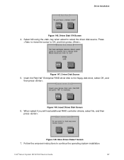
... then press . Follow the onscreen instructions to the floppy disk drive, select OK, and then press . Select fd0 using the key when asked if you will load additional RAID controller drivers, select No, and then press . More Driver Disks? Figure 147. Screen 7. Press to move the cursor to select the driver disk source. Insert Driver Disk Screen 6. Driver Disk Y/N Screen 4. Figure 148. Figure 149. Driver Disk Source 5. Intel® Server System SR1670HV Service Guide 97 Driver Installation Figure 146.
... then press . Follow the onscreen instructions to the floppy disk drive, select OK, and then press . Select fd0 using the key when asked if you will load additional RAID controller drivers, select No, and then press . More Driver Disks? Figure 147. Screen 7. Press to move the cursor to select the driver disk source. Insert Driver Disk Screen 6. Driver Disk Y/N Screen 4. Figure 148. Figure 149. Driver Disk Source 5. Intel® Server System SR1670HV Service Guide 97 Driver Installation Figure 146.
Service Guide
Page 119
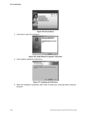
Figure 166. Updating the VGA Driver 5. Click Next to restart your computer before using the program. 104 Intel® Server System SR1670HV Service Guide Figure 167. When the installation completes, click Finish to start the installation. Install Wizard for Aspeed* VGA Driver 4. Drivers Menu 3. Click Install to update the VGA driver. Driver Installation Figure 165.
Figure 166. Updating the VGA Driver 5. Click Next to restart your computer before using the program. 104 Intel® Server System SR1670HV Service Guide Figure 167. When the installation completes, click Finish to start the installation. Install Wizard for Aspeed* VGA Driver 4. Drivers Menu 3. Click Install to update the VGA driver. Driver Installation Figure 165.
Service Guide
Page 120
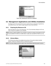
... VGA Driver Installation 8.5 Management Applications and Utilities Installation The Resource CD that came with the server contains drivers, management applications, and utilities that you can install to locate the file ASSETUP.EXE from the BIN folder. NOTE: If Autorun is enabled in your computer. Driver Installation Figure 168. NOTE: The screen display and driver options vary under different operating system versions. Drivers Menu Intel® Server System SR1670HV Service Guide 105 Double-click the ASSETUP.EXE to activate the devices...
... VGA Driver Installation 8.5 Management Applications and Utilities Installation The Resource CD that came with the server contains drivers, management applications, and utilities that you can install to locate the file ASSETUP.EXE from the BIN folder. NOTE: If Autorun is enabled in your computer. Driver Installation Figure 168. NOTE: The screen display and driver options vary under different operating system versions. Drivers Menu Intel® Server System SR1670HV Service Guide 105 Double-click the ASSETUP.EXE to activate the devices...


