
Service Guide
Page 5
...-by step instructions on how to add and replace components on using the utilities that are responsible for troubleshooting, upgrading, and repairing this chapter for purchasing and using the Intel® Server System SR1560SF. Information about the specific BIOS settings and screens is written for system technicians who are shipped with the board or that give additional details on adding and replacing components. Preface About this manual, you will find technical specifications, regulatory...
...-by step instructions on how to add and replace components on using the utilities that are responsible for troubleshooting, upgrading, and repairing this chapter for purchasing and using the Intel® Server System SR1560SF. Information about the specific BIOS settings and screens is written for system technicians who are shipped with the board or that give additional details on adding and replacing components. Preface About this manual, you will find technical specifications, regulatory...

Service Guide
Page 6
... documents: • Intel® Server Board S5400SF Technical Product Specification • Intel® Server System SR1560SF Technical Product Specification There are two versions of each server system are listed below as the "hardware box" • PCIe* riser card assembly, installed in the server system • Optical drive tray assembly (tray and interposer board), in hardware box • Optical drive cable, in hardware box • Attention document, in the server system product box • Quick Start User's Guide, in the server system product box...
... documents: • Intel® Server Board S5400SF Technical Product Specification • Intel® Server System SR1560SF Technical Product Specification There are two versions of each server system are listed below as the "hardware box" • PCIe* riser card assembly, installed in the server system • Optical drive tray assembly (tray and interposer board), in hardware box • Optical drive cable, in hardware box • Attention document, in the server system product box • Quick Start User's Guide, in the server system product box...

Service Guide
Page 11
... outlet. Intel® Server System SR1560SF Service Guide xi You must unplug the AC power cord from the server, place the board component side up on power, telephone, and communication cables. To remove power from system, you may be extremely sensitive to the assembly instructions in this guide or any components. Otherwise, personal injury or equipment damage can damage disk drives, boards, and other tool you use to remove a jumper, or...
... outlet. Intel® Server System SR1560SF Service Guide xi You must unplug the AC power cord from the server, place the board component side up on power, telephone, and communication cables. To remove power from system, you may be extremely sensitive to the assembly instructions in this guide or any components. Otherwise, personal injury or equipment damage can damage disk drives, boards, and other tool you use to remove a jumper, or...
Service Guide
Page 15
... Drive System 54 Replacing a System Fan ...55 Installing and Removing the Rack Handles 57 Installing the Rack Handles 57 Removing the Rack Handles 57 Chapter 4: Server Utilities 59 Using the BIOS Setup Utility 59 Starting Setup ...59 If You Cannot Access Setup 59 Setup Menus ...59 Upgrading the BIOS ...61 Preparing for the Upgrade 61 Upgrading the BIOS ...62 Clearing the CMOS ...62 Resetting the Password ...63 Appendix A: Technical Reference 65 600W Single Power Supply Input Voltages 65 System Environmental Specifications 65 Appendix B: Intel® Server...
... Drive System 54 Replacing a System Fan ...55 Installing and Removing the Rack Handles 57 Installing the Rack Handles 57 Removing the Rack Handles 57 Chapter 4: Server Utilities 59 Using the BIOS Setup Utility 59 Starting Setup ...59 If You Cannot Access Setup 59 Setup Menus ...59 Upgrading the BIOS ...61 Preparing for the Upgrade 61 Upgrading the BIOS ...62 Clearing the CMOS ...62 Resetting the Password ...63 Appendix A: Technical Reference 65 600W Single Power Supply Input Voltages 65 System Environmental Specifications 65 Appendix B: Intel® Server...

Service Guide
Page 19
... Slimline Optical Drive from the Server System 32 Figure 30. Light Guided Diagnostic LEDs 12 Figure 9. Removing the Front Bezel 22 Figure 15. Installing the Initial Four DIMMs 26 Figure 22. Removing Hot-swap Disk Carrier from the Tray 38 Figure 40. Installing an Optical Drive into the Server System 39 Intel® Server System SR1560SF Service Guide xix List of Figures Figure 1. Standard Control Panel 16 Figure 12. Installing the Processor 28 Figure 25. Recovery Jumpers 11 Figure 8. Optional...
... Slimline Optical Drive from the Server System 32 Figure 30. Light Guided Diagnostic LEDs 12 Figure 9. Removing the Front Bezel 22 Figure 15. Installing the Initial Four DIMMs 26 Figure 22. Removing Hot-swap Disk Carrier from the Tray 38 Figure 40. Installing an Optical Drive into the Server System 39 Intel® Server System SR1560SF Service Guide xix List of Figures Figure 1. Standard Control Panel 16 Figure 12. Installing the Processor 28 Figure 25. Recovery Jumpers 11 Figure 8. Optional...

Service Guide
Page 20
... Battery 51 Figure 57. Diagnostic LED Placement Diagram 71 xx Intel® Server System SR1560SF Service Guide Removing the Rack Handle 57 Figure 67. Installing a Full Height Add-In Card 40 Figure 43. Installing the Rack Handle 57 Figure 66. Removing the Backplane from the Server System 43 Figure 48. Removing the Control Panel Module (Fixed Drive System 54 Figure 62. Removing the Server Board 48 Figure 55. Installing Control Panel Module into the Server System 44 Figure 49. Removing the Fan Board...
... Battery 51 Figure 57. Diagnostic LED Placement Diagram 71 xx Intel® Server System SR1560SF Service Guide Removing the Rack Handle 57 Figure 67. Installing a Full Height Add-In Card 40 Figure 43. Installing the Rack Handle 57 Figure 66. Removing the Backplane from the Server System 43 Figure 48. Removing the Control Panel Module (Fixed Drive System 54 Figure 62. Removing the Server Board 48 Figure 55. Installing Control Panel Module into the Server System 44 Figure 49. Removing the Fan Board...

Service Guide
Page 26
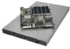
...SW RAID 5 with enablement key • Optional Intel® Remote Management Module 2 • Optional Intel® Remote Management Module 2 NIC National Semiconductor* PC87427 controller On-board ATI* ES1000 video controller with 16 MB DDR SDRAM 4 Intel® Server System SR1560SF Service Guide For a complete list of supported processors, see: http://support.intel.com/support/motherboards/server/ s5400sf/compat.htm Sixteen DIMM slots • Support for stacked DDR2 667/800 MHz FBDIMM memory Intel® 5400 Chipset, consisting of the server system. Intel® Server System SR1560SF...
...SW RAID 5 with enablement key • Optional Intel® Remote Management Module 2 • Optional Intel® Remote Management Module 2 NIC National Semiconductor* PC87427 controller On-board ATI* ES1000 video controller with 16 MB DDR SDRAM 4 Intel® Server System SR1560SF Service Guide For a complete list of supported processors, see: http://support.intel.com/support/motherboards/server/ s5400sf/compat.htm Sixteen DIMM slots • Support for stacked DDR2 667/800 MHz FBDIMM memory Intel® 5400 Chipset, consisting of the server system. Intel® Server System SR1560SF...

Service Guide
Page 27
... with enablement key • Slimline bay for 10/100/1000 Mbit/sec Ethernet LAN connectivity • One PCI Express* x16 GEN2 add-in power supply • One front panel USB 2.0 port • Two back I/O USB 2.0 ports Intel® System Management Software Intel® Server System SR1560SF Service Guide 5 Two SATA drives • Hot-swap drive system: - Intel® Server System SR1560SF Feature Summary Feature LAN Expansion Capabilities Hard Drive Options Peripherals Control Panel LEDs and displays Power Supply Fans USB System Management Description Intel® 82563EB dual port...
... with enablement key • Slimline bay for 10/100/1000 Mbit/sec Ethernet LAN connectivity • One PCI Express* x16 GEN2 add-in power supply • One front panel USB 2.0 port • Two back I/O USB 2.0 ports Intel® System Management Software Intel® Server System SR1560SF Service Guide 5 Two SATA drives • Hot-swap drive system: - Intel® Server System SR1560SF Feature Summary Feature LAN Expansion Capabilities Hard Drive Options Peripherals Control Panel LEDs and displays Power Supply Fans USB System Management Description Intel® 82563EB dual port...

Service Guide
Page 31
...POST Code Diagnostic LEDs F. SATA0 X. SATA 3 AA. Power Supply Management Connector T. Dual Port USB 2.0 Header V. Chassis Intrusion Switch Header II. SATA SW RAID 5 Activation Key Connector DD. External IO Connectors B. Battery U. SATA 4 Z. IO Module Option Connector E. Serial 'A' Header AF002159 C. CPU Power Connector R. Server Board Connector and Component Locations Intel® Server System SR1560SF Service Guide 9 Intel® Remote Management Module 2 2 Connector EE. Serial 'B' Port Configuration Jumper L. Fan Board Connector P. Password Clear...
...POST Code Diagnostic LEDs F. SATA0 X. SATA 3 AA. Power Supply Management Connector T. Dual Port USB 2.0 Header V. Chassis Intrusion Switch Header II. SATA SW RAID 5 Activation Key Connector DD. External IO Connectors B. Battery U. SATA 4 Z. IO Module Option Connector E. Serial 'A' Header AF002159 C. CPU Power Connector R. Server Board Connector and Component Locations Intel® Server System SR1560SF Service Guide 9 Intel® Remote Management Module 2 2 Connector EE. Serial 'B' Port Configuration Jumper L. Fan Board Connector P. Password Clear...
Service Guide
Page 33
... Force Update Mode is enabled. Figure 7. Recovery Jumpers Intel® Server System SR1560SF Service Guide 11 These pins should be jumpered on 1-2 for normal operation. See "Resetting the Password" on 1-2 for complete password reset instructions. These pins should be cleared on the next reset. These pins should be jumpered on page -63 for normal operation. Password Reset BMC Force Update Mode 22 33 Disable Enable 2 CMOS 3 Clear AF002170 Jumper Name Jumper Purpose CMOS Clear Password Clear BMC Force Update Mode If pins 2-3 are jumpered, the CMOS settings...
... Force Update Mode is enabled. Figure 7. Recovery Jumpers Intel® Server System SR1560SF Service Guide 11 These pins should be jumpered on 1-2 for normal operation. See "Resetting the Password" on 1-2 for complete password reset instructions. These pins should be cleared on the next reset. These pins should be jumpered on page -63 for normal operation. Password Reset BMC Force Update Mode 22 33 Disable Enable 2 CMOS 3 Clear AF002170 Jumper Name Jumper Purpose CMOS Clear Password Clear BMC Force Update Mode If pins 2-3 are jumpered, the CMOS settings...
Service Guide
Page 36
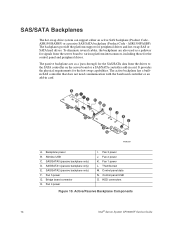
... server board or a SAS/SATA controller add-in card. A BC DE O O F G H I . Fan 4 power I J K L O N M AF002361 A. Control panel data N. SAS/SATA Backplanes The hot-swap drive system can support either an active SAS backplane (Product Code ASR1500SASBP) or a passive SAS/SATA backplane (Product Code - It provides the physical requirements for peripheral drives and hot-swap SAS or SATA hard drives. Slimline USB C. SAS/SATA2 (passive backplane only) F. Active/Passive Backplane Components 14 Intel® Server System SR1560SF Service Guide Fan 5 power G. HDD connectors...
... server board or a SAS/SATA controller add-in card. A BC DE O O F G H I . Fan 4 power I J K L O N M AF002361 A. Control panel data N. SAS/SATA Backplanes The hot-swap drive system can support either an active SAS backplane (Product Code ASR1500SASBP) or a passive SAS/SATA backplane (Product Code - It provides the physical requirements for peripheral drives and hot-swap SAS or SATA hard drives. Slimline USB C. SAS/SATA2 (passive backplane only) F. Active/Passive Backplane Components 14 Intel® Server System SR1560SF Service Guide Fan 5 power G. HDD connectors...
Service Guide
Page 37
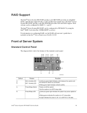
... System Standard Control Panel The diagram below shows the features of the standard control panel. No light indicates the power is off the system. B. Intel® Server System SR1560SF Service Guide 15 The Intel® Server System SR1560SF (product code SR1560SFHS) provides SAS and SATA support. Both systems can be configured for SW RAID 5 by using the Intel® RAID Activation Key AXXRAKSW5 accessory. D. Powers on configuring RAID, see the RAID software user's guide that supports both 1.5 and 3.0 Gbps data transfer rates. Blinking green light indicates network...
... System Standard Control Panel The diagram below shows the features of the standard control panel. No light indicates the power is off the system. B. Intel® Server System SR1560SF Service Guide 15 The Intel® Server System SR1560SF (product code SR1560SFHS) provides SAS and SATA support. Both systems can be configured for SW RAID 5 by using the Intel® RAID Activation Key AXXRAKSW5 accessory. D. Powers on configuring RAID, see the RAID software user's guide that supports both 1.5 and 3.0 Gbps data transfer rates. Blinking green light indicates network...

Service Guide
Page 38
... the bezel is off the system identification LED. I. K. Feature Hard Disk Drive Activity LED System Status LED System Identification LED System Identification Button Reset Button USB 2.0 Port NMI Button Video Port Function Random blinking green light indicates hard disk drive activity (SAS or SATA). Solid amber indicates a critical or non-recoverable condition. Turns on design that has the standard control panel installed (with the standard control panel. 16 Intel® Server System SR1560SF Service Guide The front and rear video ports cannot be used at the same time. Solid...
... the bezel is off the system identification LED. I. K. Feature Hard Disk Drive Activity LED System Status LED System Identification LED System Identification Button Reset Button USB 2.0 Port NMI Button Video Port Function Random blinking green light indicates hard disk drive activity (SAS or SATA). Solid amber indicates a critical or non-recoverable condition. Turns on design that has the standard control panel installed (with the standard control panel. 16 Intel® Server System SR1560SF Service Guide The front and rear video ports cannot be used at the same time. Solid...

Service Guide
Page 40
... code SR1560SFHS) only. Note: Drives can consume up to 17 watts of 45C. 18 Intel® Server System SR1560SF Service Guide A B D C AF002191 . However, only the two left drive bays can be purchased separately. The third hard drive bay is supported on installing hard drives, see "Installing and Removing a Fixed Hard Drive" or "Installing and Removing a Hot-swap Hard Drive". Note: The USB floppy drive kit is not used to run at a maximum ambient temperature of power each. Control panel C. The drives...
... code SR1560SFHS) only. Note: Drives can consume up to 17 watts of 45C. 18 Intel® Server System SR1560SF Service Guide A B D C AF002191 . However, only the two left drive bays can be purchased separately. The third hard drive bay is supported on installing hard drives, see "Installing and Removing a Fixed Hard Drive" or "Installing and Removing a Hot-swap Hard Drive". Note: The USB floppy drive kit is not used to run at a maximum ambient temperature of power each. Control panel C. The drives...

Service Guide
Page 56
... it to a list of fixed mount hard drives can be performed by itself . Remove the four screws securing the drive blank in the fully open position, slide the drive carrier into the drive carrier, using the four screws you removed from inside the chassis. Note: All hard drive carriers must be installed in the Intel® Server System SR1560SF product code SR1560SF. Note: The extraction of supported hardware. If you...
... it to a list of fixed mount hard drives can be performed by itself . Remove the four screws securing the drive blank in the fully open position, slide the drive carrier into the drive carrier, using the four screws you removed from inside the chassis. Note: All hard drive carriers must be installed in the Intel® Server System SR1560SF product code SR1560SF. Note: The extraction of supported hardware. If you...
Service Guide
Page 73
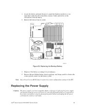
... the system, turn off the system by pressing the power button, and unplug the AC power cord from its socket. AF002375 Figure 56. Replacing the Power Supply Caution: The power supply is not hot-swappable. Gently push down on the screwdriver to the RTC. Intel® Server System SR1560SF Service Guide 51 Note: You will need to run BIOS Setup to restore the system configuration settings to lift the battery. 2. 1. Dispose of service, turn off all peripheral devices connected...
... the system, turn off the system by pressing the power button, and unplug the AC power cord from its socket. AF002375 Figure 56. Replacing the Power Supply Caution: The power supply is not hot-swappable. Gently push down on the screwdriver to the RTC. Intel® Server System SR1560SF Service Guide 51 Note: You will need to run BIOS Setup to restore the system configuration settings to lift the battery. 2. 1. Dispose of service, turn off all peripheral devices connected...

Service Guide
Page 74
.... 52 Intel® Server System SR1560SF Service Guide Before removing or replacing the control panel, you must be replaced if it fails or if one of service, turn off all power cables in step 1 above , and reconnect AC power cord. Installing Power Supply into it out (see letter "B"). Caution: The control panel is integrated into the Server System Replacing the Control Panel Module (Hot-swap Drive System) Your server must first take the server out of the fans that is...
.... 52 Intel® Server System SR1560SF Service Guide Before removing or replacing the control panel, you must be replaced if it fails or if one of service, turn off all power cables in step 1 above , and reconnect AC power cord. Installing Power Supply into it out (see letter "B"). Caution: The control panel is integrated into the Server System Replacing the Control Panel Module (Hot-swap Drive System) Your server must first take the server out of the fans that is...

Service Guide
Page 76
... "D"). 5. Slide the control panel out through the front of service, turn off all peripheral devices connected to the system, turn off the system by pressing the power button, and unplug the AC power cord from the retaining clip on the fan board (see letter "C"). 4. Removing the Control Panel Module (Fixed Drive System) 54 Intel® Server System SR1560SF Service Guide Remove the cables from the system or wall outlet. 1. Before removing or replacing the control panel, you must be operated with a control panel installed. A C D B E AF002344...
... "D"). 5. Slide the control panel out through the front of service, turn off all peripheral devices connected to the system, turn off the system by pressing the power button, and unplug the AC power cord from the retaining clip on the fan board (see letter "C"). 4. Removing the Control Panel Module (Fixed Drive System) 54 Intel® Server System SR1560SF Service Guide Remove the cables from the system or wall outlet. 1. Before removing or replacing the control panel, you must be operated with a control panel installed. A C D B E AF002344...
Service Guide
Page 84
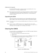
... the BIOS image file before attempting a BIOS upgrade. When the update completes, remove the bootable media from the normal operation position, CMOS Protect at pins 1 and 2, to complete the upgrade. Doing so may encounter a CMOS Checksum error or other information to the CMOS Clear Force Erase position, covering pins 2 and 3. Move the jumper from which you enter Setup, check your settings, save your hard drive. Caution: Do not power down the system and boot it again. Power...
... the BIOS image file before attempting a BIOS upgrade. When the update completes, remove the bootable media from the normal operation position, CMOS Protect at pins 1 and 2, to complete the upgrade. Doing so may encounter a CMOS Checksum error or other information to the CMOS Clear Force Erase position, covering pins 2 and 3. Move the jumper from which you enter Setup, check your settings, save your hard drive. Caution: Do not power down the system and boot it again. Power...
Service Guide
Page 85
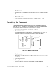
... the "clear" position clears both passwords. do not disconnect the AC power. 2. Move the jumper from the normal operation position, Password Clear Protect, at pins 1 and 2 to the CMOS Protect location, covering pins 1 and 2. 6. Password Reset Jumper 4. Return the Password Reset jumper to its original position before a new password(s) can be set. 1. The CMOS is lost or forgotten, moving the password reset jumper into the BIOS setup. Open the server system. 3. Power up the system. 8. Wait five seconds. 5. Password Reset BMC Force Update Mode 22 33 Disable Enable 2 CMOS...
... the "clear" position clears both passwords. do not disconnect the AC power. 2. Move the jumper from the normal operation position, Password Clear Protect, at pins 1 and 2 to the CMOS Protect location, covering pins 1 and 2. 6. Password Reset Jumper 4. Return the Password Reset jumper to its original position before a new password(s) can be set. 1. The CMOS is lost or forgotten, moving the password reset jumper into the BIOS setup. Open the server system. 3. Power up the system. 8. Wait five seconds. 5. Password Reset BMC Force Update Mode 22 33 Disable Enable 2 CMOS...


