User Guide
Page 5
... find a list of technical documents that give additional details on adding and replacing components. This manual is available in the Intel® 5000 Series Chipsets Server Board Family Datasheet. Information about the specific BIOS settings and screens is written for installing or replacing components such as the fans, power supply, drives, and other components. See "Server System References" for step-by step instructions on how to add and replace components on using the Intel® Server System SR1500AL. For...
... find a list of technical documents that give additional details on adding and replacing components. This manual is available in the Intel® 5000 Series Chipsets Server Board Family Datasheet. Information about the specific BIOS settings and screens is written for installing or replacing components such as the fans, power supply, drives, and other components. See "Server System References" for step-by step instructions on how to add and replace components on using the Intel® Server System SR1500AL. For...

User Guide
Page 11
... damage disk drives, boards, and other regulatory approvals of fine needle nosed pliers. If one is unplugged before opening it. Intel® Server System SR1500AL User's Guide xi To remove power from system, you open the chassis, add, or remove any unpainted metal surface on the board. Use a conductive foam pad if available but not squeeze, the pliers or other resource as a reference, pay close attention to remove a jumper, or...
... damage disk drives, boards, and other regulatory approvals of fine needle nosed pliers. If one is unplugged before opening it. Intel® Server System SR1500AL User's Guide xi To remove power from system, you open the chassis, add, or remove any unpainted metal surface on the board. Use a conductive foam pad if available but not squeeze, the pliers or other resource as a reference, pay close attention to remove a jumper, or...

User Guide
Page 14
...or SATA Hot-swap Hard Disk Drive 42 Installing or Removing a Slimline Optical Drive or Internal USB Floppy 42 Installing a Slimline Optical Drive or Internal USB Floppy 43 Removing a Slimline Optical Drive or Internal USB Floppy 44 Filling Empty Server System Bays 46 Installing and Removing the PCI Riser Assembly 47 Removing the PCI Riser Assembly 47 Installing the PCI Riser Assembly 48 Replacing a PCI Riser Card 49 Removing the PCI Express* Riser Card 49 Installing the PCI-X* Riser Card 51 Installing and Removing a PCI Add-in Card 52 Installing a PCI Add-in Card 52 Removing a PCI...
...or SATA Hot-swap Hard Disk Drive 42 Installing or Removing a Slimline Optical Drive or Internal USB Floppy 42 Installing a Slimline Optical Drive or Internal USB Floppy 43 Removing a Slimline Optical Drive or Internal USB Floppy 44 Filling Empty Server System Bays 46 Installing and Removing the PCI Riser Assembly 47 Removing the PCI Riser Assembly 47 Installing the PCI Riser Assembly 48 Replacing a PCI Riser Card 49 Removing the PCI Express* Riser Card 49 Installing the PCI-X* Riser Card 51 Installing and Removing a PCI Add-in Card 52 Installing a PCI Add-in Card 52 Removing a PCI...

User Guide
Page 15
... Proper Operation of Key System Lights 87 Confirming Loading of the Operating System 87 Specific Problems and Corrective Actions 88 Power Light Does Not Light 88 No Characters Appear on Screen 89 Characters Are Distorted or Incorrect 89 System Cooling Fans Do Not Rotate Properly 90 Drive Activity Light Does Not Light 90 CD-ROM Drive or DVD-ROM Drive Activity Light Does Not Light 90 Cannot Connect to a Server 91 Problems with Network 91 System Boots when Installing PCI Card 92 Intel® Server System SR1500AL User's Guide...
... Proper Operation of Key System Lights 87 Confirming Loading of the Operating System 87 Specific Problems and Corrective Actions 88 Power Light Does Not Light 88 No Characters Appear on Screen 89 Characters Are Distorted or Incorrect 89 System Cooling Fans Do Not Rotate Properly 90 Drive Activity Light Does Not Light 90 CD-ROM Drive or DVD-ROM Drive Activity Light Does Not Light 90 Cannot Connect to a Server 91 Problems with Network 91 System Boots when Installing PCI Card 92 Intel® Server System SR1500AL User's Guide...
User Guide
Page 19
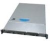
.... Removing Hot-swap Disk Carrier from Drive Carrier 40 Figure 32. Installing an Optical Drive Assembly into the Server System 48 Figure 40. List of Figures Figure 1. Intel® Integrated Server System SR1500AL 3 Figure 2. ChassisComponents 6 Figure 3. Recovery Jumpers ...9 Figure 6. Light Guided Diagnostic LEDs 10 Figure 7. Active Backplane Components 12 Figure 9. Intel® Local Control Panel 16 Figure 12. Optional Peripherals 18 Figure 14. Front View with Bezel supporting the Standard Control Panel 24 Figure 15. Installing the Processor...
.... Removing Hot-swap Disk Carrier from Drive Carrier 40 Figure 32. Installing an Optical Drive Assembly into the Server System 48 Figure 40. List of Figures Figure 1. Intel® Integrated Server System SR1500AL 3 Figure 2. ChassisComponents 6 Figure 3. Recovery Jumpers ...9 Figure 6. Light Guided Diagnostic LEDs 10 Figure 7. Active Backplane Components 12 Figure 9. Intel® Local Control Panel 16 Figure 12. Optional Peripherals 18 Figure 14. Front View with Bezel supporting the Standard Control Panel 24 Figure 15. Installing the Processor...

User Guide
Page 20
... Server System 57 Figure 48. Removing the Intel® Local Control Panel Module 68 Figure 58. I Installing a Fan into the Server System 68 Figure 59. Diagnostic LED Placement Diagram 102 xx Intel® Server System SR1500AL User's Guide Installing Control Panel Module into the Fan Module 70 Figure 61. Replacing the Backup Battery 65 Figure 55. Installing the Backplane into the Server System 60 Figure 51. Removing a Full Height Add-In Card 53 Figure 44. Connecting SATA Cables 80 Figure 67. Removing Power Supply Module from the Fan...
... Server System 57 Figure 48. Removing the Intel® Local Control Panel Module 68 Figure 58. I Installing a Fan into the Server System 68 Figure 59. Diagnostic LED Placement Diagram 102 xx Intel® Server System SR1500AL User's Guide Installing Control Panel Module into the Fan Module 70 Figure 61. Replacing the Backup Battery 65 Figure 55. Installing the Backplane into the Server System 60 Figure 51. Removing a Full Height Add-In Card 53 Figure 44. Connecting SATA Cables 80 Figure 67. Removing Power Supply Module from the Fan...

User Guide
Page 27
... Intel® Local Control Panel: • NIC1 Activity • NIC2 Activity • Power / Sleep • System Status • System Identification • Hard Drive Activity • LCD Display Single 600 W power supply module • Six 4-pin fan headers supporting two processor fans, and four system fans • Two non-redundant fans in power supply • Two front panel USB ports • One internal USB header providing two USB ports Intel® System Management Software Intel® Server System SR1500AL User's Guide 5 Table 2. only 3 SATA connectors are used in the system...
... Intel® Local Control Panel: • NIC1 Activity • NIC2 Activity • Power / Sleep • System Status • System Identification • Hard Drive Activity • LCD Display Single 600 W power supply module • Six 4-pin fan headers supporting two processor fans, and four system fans • Two non-redundant fans in power supply • Two front panel USB ports • One internal USB header providing two USB ports Intel® System Management Software Intel® Server System SR1500AL User's Guide 5 Table 2. only 3 SATA connectors are used in the system...

User Guide
Page 40
...or Serial ATA (SATA) hot-swap drives. Slimline drive bay (drive not included) B. Note: The Intel® Server System SR1500AL does not support all SAS or Serial ATA (SATA) hard drives. A B D C TP02156 . Hard drive bays (drives not included) Figure 13. Note: SAS drives are supported on installing hard drives, see "Installing and Removing a Hot-swap Hard Drive". To use the bay for an Internet link to run at a maximum ambient temperature of supported hardware. 18 Intel® Server System SR1500AL User's Guide Hard Drive Status LEDs D. Control panel (standard control panel...
...or Serial ATA (SATA) hot-swap drives. Slimline drive bay (drive not included) B. Note: The Intel® Server System SR1500AL does not support all SAS or Serial ATA (SATA) hard drives. A B D C TP02156 . Hard drive bays (drives not included) Figure 13. Note: SAS drives are supported on installing hard drives, see "Installing and Removing a Hot-swap Hard Drive". To use the bay for an Internet link to run at a maximum ambient temperature of supported hardware. 18 Intel® Server System SR1500AL User's Guide Hard Drive Status LEDs D. Control panel (standard control panel...

User Guide
Page 88
... Intel® Server System SR1500AL User's Guide A B A AF000366 Figure 55. B A B AF000367 Figure 56. The power supply can be replaced if it fails. Remove the server system cover. Lift the power supply to the system, turn off the system by sliding it clicks into it fails or if one of this book. To replace the power supply, use the following instructions. 1. Replacing the Power Supply Caution: The power supply is integrated into place. Power down the server and unplug all peripheral devices connected...
... Intel® Server System SR1500AL User's Guide A B A AF000366 Figure 55. B A B AF000367 Figure 56. The power supply can be replaced if it fails. Remove the server system cover. Lift the power supply to the system, turn off the system by sliding it clicks into it fails or if one of this book. To replace the power supply, use the following instructions. 1. Replacing the Power Supply Caution: The power supply is integrated into place. Power down the server and unplug all peripheral devices connected...

User Guide
Page 89
... below for replacing the standard control panel and the Intel® Local Control Panel are noted. Plug all peripheral devices and the AC power cable(s). 3. Replacing the Control Panel The steps for both varieties of the control panel. Before removing or replacing the control panel, you must be operated with a control panel installed. For instructions, see "Removing the Front Bezel". 4. Intel® Server System SR1500AL User's Guide 67 6. For instructions, see "Removing the System Cover". 5. Unplug the front panel and USB cables from the system or wall outlet...
... below for replacing the standard control panel and the Intel® Local Control Panel are noted. Plug all peripheral devices and the AC power cable(s). 3. Replacing the Control Panel The steps for both varieties of the control panel. Before removing or replacing the control panel, you must be operated with a control panel installed. For instructions, see "Removing the Front Bezel". 4. Intel® Server System SR1500AL User's Guide 67 6. For instructions, see "Removing the System Cover". 5. Unplug the front panel and USB cables from the system or wall outlet...
User Guide
Page 95
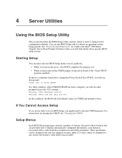
.... 4 Server Utilities Using the BIOS Setup Utility This section describes the BIOS Setup Utility options, which is used to the "Clear CMOS" position (enabled). Starting Setup You can run BIOS Setup with a value field that are not able to access BIOS Setup, you might need to the Intel® 5000 Series Chipsets Server Board Family Datasheet where you have moved the CMOS jumper on the server board to change server configuration defaults. If You Cannot Access Setup If you are provided only to boot. You can enter and start BIOS Setup under...
.... 4 Server Utilities Using the BIOS Setup Utility This section describes the BIOS Setup Utility options, which is used to the "Clear CMOS" position (enabled). Starting Setup You can run BIOS Setup with a value field that are not able to access BIOS Setup, you might need to the Intel® 5000 Series Chipsets Server Board Family Datasheet where you have moved the CMOS jumper on the server board to change server configuration defaults. If You Cannot Access Setup If you are provided only to boot. You can enter and start BIOS Setup under...

User Guide
Page 98
... BIOS image file before a new password(s) can be set. 1. Open the server chassis. 3. The system will reset automatically when the BIOS update process is lost or forgotten, moving the password clear jumper into the "clear" position clears both passwords. See "Server System References" for a link to complete the upgrade. Move the jumper from which you enter Setup, check your settings, save your hard drive. Obtaining the Upgrade Download the BIOS image file to the Password Clear Erase position, covering pins 2 and 3. 76 Intel® Server System SR1500AL User's Guide Note: Review...
... BIOS image file before a new password(s) can be set. 1. Open the server chassis. 3. The system will reset automatically when the BIOS update process is lost or forgotten, moving the password clear jumper into the "clear" position clears both passwords. See "Server System References" for a link to complete the upgrade. Move the jumper from which you enter Setup, check your settings, save your hard drive. Obtaining the Upgrade Download the BIOS image file to the Password Clear Erase position, covering pins 2 and 3. 76 Intel® Server System SR1500AL User's Guide Note: Review...

User Guide
Page 99
... AC power and power up the server. 8. Open the server. 3. Move the jumper from the normal operation position, CMOS Clear by going into BIOS setup. Return the Password Clear jumper to the CMOS Clear Force Erase position, covering pins 2 and 3. Intel® Server System SR1500AL User's Guide 77 BMC Force Update Mode 2 3 J1D2 Password Reset Disable 2 Enable 3 J1D1 2 Clear 3 CMOS J1D3 Figure 63. The password is now cleared and can be used to reset the configuration RAM. 1. Clearing the CMOS If you are not able to access the BIOS setup screens, the CMOS Clear jumper...
... AC power and power up the server. 8. Open the server. 3. Move the jumper from the normal operation position, CMOS Clear by going into BIOS setup. Return the Password Clear jumper to the CMOS Clear Force Erase position, covering pins 2 and 3. Intel® Server System SR1500AL User's Guide 77 BMC Force Update Mode 2 3 J1D2 Password Reset Disable 2 Enable 3 J1D1 2 Clear 3 CMOS J1D3 Figure 63. The password is now cleared and can be used to reset the configuration RAM. 1. Clearing the CMOS If you are not able to access the BIOS setup screens, the CMOS Clear jumper...
User Guide
Page 108
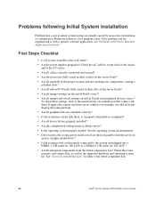
... all add-in PCI boards fully seated in their slots on the server board? • Are all jumper settings on the back of the chassis and at the wall outlet? • Are the power supplies plugged in boards and peripheral devices correct? Check the AC cable(s) on the server board correct? • Are all peripheral devices installed correctly? • If the system has a hard disk drive, is a less frequent cause. See the operating system...
... all add-in PCI boards fully seated in their slots on the server board? • Are all jumper settings on the back of the chassis and at the wall outlet? • Are the power supplies plugged in boards and peripheral devices correct? Check the AC cable(s) on the server board correct? • Are all peripheral devices installed correctly? • If the system has a hard disk drive, is a less frequent cause. See the operating system...

User Guide
Page 109
... bootable device." Hardware Diagnostic Testing This section provides a more detailed approach to identifying a hardware problem and locating its brightness and contrast controls to at least two thirds of their maximum ranges (see the documentation supplied with your video display monitor and keyboard are illuminated, see "Make sure the BIOS is no CD-ROM / DVD disk in the system. Intel® Server System SR1500AL User's Guide 87 Verifying Proper Operation of Key System Lights As POST determines the system configuration, it tests for...
... bootable device." Hardware Diagnostic Testing This section provides a more detailed approach to identifying a hardware problem and locating its brightness and contrast controls to at least two thirds of their maximum ranges (see the documentation supplied with your video display monitor and keyboard are illuminated, see "Make sure the BIOS is no CD-ROM / DVD disk in the system. Intel® Server System SR1500AL User's Guide 87 Verifying Proper Operation of Key System Lights As POST determines the system configuration, it tests for...

User Guide
Page 111
... video monitor signal cable properly installed? • Does this video monitor work correctly if plugged into a different system? • Is the onboard video controller enabled in the BIOS? • Remove all add-in the server board connector. 3. If successful, add the cards back in and turned on? Verify that the video controller board is it by turning the "Num Lock" function on and off to the system requirements. • Remove the memory DIMMs and re-seat them . Intel® Server System SR1500AL User's Guide...
... video monitor signal cable properly installed? • Does this video monitor work correctly if plugged into a different system? • Is the onboard video controller enabled in the BIOS? • Remove all add-in the server board connector. 3. If successful, add the cards back in and turned on? Verify that the video controller board is it by turning the "Num Lock" function on and off to the system requirements. • Remove the memory DIMMs and re-seat them . Intel® Server System SR1500AL User's Guide...
User Guide
Page 113
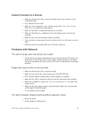
... changing interrupts. See the documentation that came with other adapter supports shared interrupts. The add-in adapter stopped working when an add-in adapter was installed. • Make sure the cable is connected to the port from the onboard network controller. • Make sure your PCI card(s) for a link to the current version. • Make sure the other PCI drivers. Make sure your operating system supports shared interrupts. • Try reseating the add-in a different slot. See "Server System...
... changing interrupts. See the documentation that came with other adapter supports shared interrupts. The add-in adapter stopped working when an add-in adapter was installed. • Make sure the cable is connected to the port from the onboard network controller. • Make sure your PCI card(s) for a link to the current version. • Make sure the other PCI drivers. Make sure your operating system supports shared interrupts. • Try reseating the add-in a different slot. See "Server System...
User Guide
Page 114
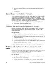
... Software Problems that occur after the system hardware and software have power going to the software configuration. Unauthorized copies often do not work. • If you are running the software from a CD-ROM or DVD-ROM, try a different disk. • Make sure the correct device drivers installed. Check the following : • Make sure the system meets the minimum hardware requirements for the system. Before installing a PCI card, you have turned the system power off the server power by file corruption or changes...
... Software Problems that occur after the system hardware and software have power going to the software configuration. Unauthorized copies often do not work. • If you are running the software from a CD-ROM or DVD-ROM, try a different disk. • Make sure the correct device drivers installed. Check the following : • Make sure the system meets the minimum hardware requirements for the system. Before installing a PCI card, you have turned the system power off the server power by file corruption or changes...

User Guide
Page 115
... random errors in BIOS Setup. • Make sure the drive is connected correctly and that might have not exceeded the power budget for your drive documentation for the Intel® chipsets, onboard NICs, and other random component failures. • If you are set correctly. See your drives. • If using a RAID configuration with SCSI or SATA drives, make sure the RAID card is incorrect), a marginal power supply, or other components. Intel® Server System SR1500AL User's Guide 93...
... random errors in BIOS Setup. • Make sure the drive is connected correctly and that might have not exceeded the power budget for your drive documentation for the Intel® chipsets, onboard NICs, and other random component failures. • If you are set correctly. See your drives. • If using a RAID configuration with SCSI or SATA drives, make sure the RAID card is incorrect), a marginal power supply, or other components. Intel® Server System SR1500AL User's Guide 93...
User Guide
Page 116
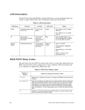
... Beep Codes Number of their use Server Management software to Take Memory error. Fatal error indicating a possible serious system problem. Remove all error conditions are removed, insert the cards one at a time, booting the system between each card addition, until the beeps again occur to system video initialization, the BIOS uses these LEDs with known good modules. LED Information The Intel® Server Board S5000PAL includes LEDs that not all add-in card. Table 8. LED Information LED Name Power ID System Status Function Location Indicates system power Front control...
... Beep Codes Number of their use Server Management software to Take Memory error. Fatal error indicating a possible serious system problem. Remove all error conditions are removed, insert the cards one at a time, booting the system between each card addition, until the beeps again occur to system video initialization, the BIOS uses these LEDs with known good modules. LED Information The Intel® Server Board S5000PAL includes LEDs that not all add-in card. Table 8. LED Information LED Name Power ID System Status Function Location Indicates system power Front control...


