Product Specification
Page 9
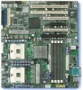
... only 134 Figure 19. Supported DDR-266 DIMM Populations 24 Table 5. Possible Memory Capacities 25 Table 8. Suggested SEC Threashold Prescale Settings 27 Table 9. Interrupt Definitions...33 Table 13. PCI Configuration IDs and Device Numbers 53 Table 20. PCI Interrupt Routing/Sharing 32... Figure 22. Sample BIOS Popup Menu 59 Table 21. BIOS Bank Jumper (J26 160 Figure 21. PCI Bus Segment Characteristics 30 Table 11. I /O GPIO Usage Table 41 Table 16. DIMM Threshold Values by DIMM Size 27 Table 10. Intel® Server Board SE7525GP2 Layout Reference 7 Table...
... only 134 Figure 19. Supported DDR-266 DIMM Populations 24 Table 5. Possible Memory Capacities 25 Table 8. Suggested SEC Threashold Prescale Settings 27 Table 9. Interrupt Definitions...33 Table 13. PCI Configuration IDs and Device Numbers 53 Table 20. PCI Interrupt Routing/Sharing 32... Figure 22. Sample BIOS Popup Menu 59 Table 21. BIOS Bank Jumper (J26 160 Figure 21. PCI Bus Segment Characteristics 30 Table 11. I /O GPIO Usage Table 41 Table 16. DIMM Threshold Values by DIMM Size 27 Table 10. Intel® Server Board SE7525GP2 Layout Reference 7 Table...
Product Specification
Page 10
... 110 Table 52. Contents Intel® Server Boards SE7320SP2 and SE7525GP2 Table 23. BIOS Setup, USB Configuration Sub-menu Selections 69 Table 31. BIOS Setup, Boot Menu Selections 73 Table 35. BIOS Setup, Hard Disk Drive Sub-Menu Selections 74 Table 38. BIOS Setup, CD/DVD Drives Sub... 71 Table 33. BIOS Setup, Boot Settings Configuration Sub-menu Selections 73 Table 36. BIOS Setup, Boot Device Priority Sub-menu Selections 74 Table 37. BIOS Setup, Removable Drives Sub-menu Selections 74 Table 39. BIOS Setup, Security Menu Options 75 Table 41. BIOS Setup, Server Menu ...
... 110 Table 52. Contents Intel® Server Boards SE7320SP2 and SE7525GP2 Table 23. BIOS Setup, USB Configuration Sub-menu Selections 69 Table 31. BIOS Setup, Boot Menu Selections 73 Table 35. BIOS Setup, Hard Disk Drive Sub-Menu Selections 74 Table 38. BIOS Setup, CD/DVD Drives Sub... 71 Table 33. BIOS Setup, Boot Settings Configuration Sub-menu Selections 73 Table 36. BIOS Setup, Boot Device Priority Sub-menu Selections 74 Table 37. BIOS Setup, Removable Drives Sub-menu Selections 74 Table 39. BIOS Setup, Security Menu Options 75 Table 41. BIOS Setup, Server Menu ...

Product Specification
Page 13
...BIOS ƒ Chapter 5: Platform Management ƒ Chapter 6: Error Reporting and Handling ƒ Chapter 7: Connector Definitions and Pin-outs ƒ Chapter 8: General Specifications ƒ Chapter 9: Product Regulatory Compliance 1.2 Server Board Use Disclaimer Intel...for this document apply to the architecture and feature set of these components. Intel Corporation can not be held responsible, if components ... meet the intended thermal requirements of the Intel® Server Board SE7320SP2 and the Intel® Server Board SE7525GP2. Introduction This Technical Product Specification (TPS...
...BIOS ƒ Chapter 5: Platform Management ƒ Chapter 6: Error Reporting and Handling ƒ Chapter 7: Connector Definitions and Pin-outs ƒ Chapter 8: General Specifications ƒ Chapter 9: Product Regulatory Compliance 1.2 Server Board Use Disclaimer Intel...for this document apply to the architecture and feature set of these components. Intel Corporation can not be held responsible, if components ... meet the intended thermal requirements of the Intel® Server Board SE7320SP2 and the Intel® Server Board SE7525GP2. Introduction This Technical Product Specification (TPS...
Product Specification
Page 25
...disabled and an error is responsible for all installed processors, all levels of an Intel supplied data block, i.e., microcode update. Intel® Server Boards SE7320SP2 and SE7525GP2 Functional Architecture 3.1.6.2 Mixed Processor Steppings For optimum system performance, only identical processors should...4.0 13 If there is reported in a system. The BIOS verifies the signature prior to set the processor frequency. If the installed processors are not supported. 3.1.6.6 Jumperless Processor Speed Settings The Intel® Xeon® processor does not utilize jumpers or ...
...disabled and an error is responsible for all installed processors, all levels of an Intel supplied data block, i.e., microcode update. Intel® Server Boards SE7320SP2 and SE7525GP2 Functional Architecture 3.1.6.2 Mixed Processor Steppings For optimum system performance, only identical processors should...4.0 13 If there is reported in a system. The BIOS verifies the signature prior to set the processor frequency. If the installed processors are not supported. 3.1.6.6 Jumperless Processor Speed Settings The Intel® Xeon® processor does not utilize jumpers or ...

Product Specification
Page 35
... List on the support website for a list of supported memory: http://support.intel.com/support/motherboards/server/se7320sp2 http://support.intel.com/support/motherboards/server/se7525gp2 The BIOS reads the Serial Presence Detect (SPD) SEEPROMs on each have four DIMM slots..., or two DIMM banks. For interleaving and RAS to step 3. 3. The memory sizing algorithm determines the size of each row of the installed memory modules. If DIMM dual pair# >= 1, set...
... List on the support website for a list of supported memory: http://support.intel.com/support/motherboards/server/se7320sp2 http://support.intel.com/support/motherboards/server/se7525gp2 The BIOS reads the Serial Presence Detect (SPD) SEEPROMs on each have four DIMM slots..., or two DIMM banks. For interleaving and RAS to step 3. 3. The memory sizing algorithm determines the size of each row of the installed memory modules. If DIMM dual pair# >= 1, set...
Product Specification
Page 38
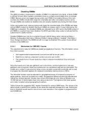
... the next system boot, memory-sizing code reads the recorded state of error count resolution. Functional Architecture Intel® Server Boards SE7320SP2 and SE7525GP2 3.5.4 Disabling DIMMs The BIOS provides a mechanism to disable a DIMM if it is detected to be adjusted for geographical areas of ...middle error number is defined to have shown that the system has no longer be re-enabled through a BIOS Setup option (Advanced Menu | Memory Configuration Sub-menu | Memory Retest | change setting to "enabled" | Exit Menu | Save changes and Exit). The threshold number must be faulty. ...
... the next system boot, memory-sizing code reads the recorded state of error count resolution. Functional Architecture Intel® Server Boards SE7320SP2 and SE7525GP2 3.5.4 Disabling DIMMs The BIOS provides a mechanism to disable a DIMM if it is detected to be adjusted for geographical areas of ...middle error number is defined to have shown that the system has no longer be re-enabled through a BIOS Setup option (Advanced Menu | Memory Configuration Sub-menu | Memory Retest | change setting to "enabled" | Exit Menu | Save changes and Exit). The threshold number must be faulty. ...

Product Specification
Page 39
... be disabled by BIOS. 3.5.5 Memory RASUM Features The Intel® E7320 MCH and Intel E7525 MCH support ...several memory RASUM (Reliability, Availability, Serviceability, Usability, and Manageability) features that can occur on each is also dependent on the DIMM size. If the CME count that occurs on Correctable Errors, Integrated Memory Initialization, and DIMM Sparing. Suggested SEC Threashold Prescale Settings... its counter value is 10h. Intel® Server Boards SE7320SP2 and SE7525GP2 Functional Architecture Table 8.
... be disabled by BIOS. 3.5.5 Memory RASUM Features The Intel® E7320 MCH and Intel E7525 MCH support ...several memory RASUM (Reliability, Availability, Serviceability, Usability, and Manageability) features that can occur on each is also dependent on the DIMM size. If the CME count that occurs on Correctable Errors, Integrated Memory Initialization, and DIMM Sparing. Suggested SEC Threashold Prescale Settings... its counter value is 10h. Intel® Server Boards SE7320SP2 and SE7525GP2 Functional Architecture Table 8.

Product Specification
Page 41
...Sparing Function To provide a more complex. The "drip rate" of the bucket is possible to set the fail-over threshold register to a non-zero value to enable the feature, and if the... The fail-over has been initiated the MCH must execute every write twice; Intel® Server Boards SE7320SP2 and SE7525GP2 Functional Architecture Note that any DIMM exceeds that value, fail-over will not... from service. This function facilitates a limited, very high speed memory test, and provides a BIOS-accessible memory zeroing capability for the size and type of memory devices in use . Only one...
...Sparing Function To provide a more complex. The "drip rate" of the bucket is possible to set the fail-over threshold register to a non-zero value to enable the feature, and if the... The fail-over has been initiated the MCH must execute every write twice; Intel® Server Boards SE7320SP2 and SE7525GP2 Functional Architecture Note that any DIMM exceeds that value, fail-over will not... from service. This function facilitates a limited, very high speed memory test, and provides a BIOS-accessible memory zeroing capability for the size and type of memory devices in use . Only one...

Product Specification
Page 43
...-mode interrupt for the devices that will be allocated to them. PCI bus numbers may change when PCI-PCI bridges are correctly set up to devices in a PCI bus, all subordinate buses are defined. If a bridge is incremented in exception of the legacy...respect to enhance the breadth of x4 (2 GB/s). 3.6.1.4 P64-Express16: x16 PCI Express bus segment Intel® Server Board SE7525GP2 only: The P64-Express16 bus segment supports x16 PCI Express signaling. 3.6.1.5 Scan Order The BIOS assigns PCI bus numbers in a depth-first hierarchy, in the chipsets. Scanning continues on this bus...
...-mode interrupt for the devices that will be allocated to them. PCI bus numbers may change when PCI-PCI bridges are correctly set up to devices in a PCI bus, all subordinate buses are defined. If a bridge is incremented in exception of the legacy...respect to enhance the breadth of x4 (2 GB/s). 3.6.1.4 P64-Express16: x16 PCI Express bus segment Intel® Server Board SE7525GP2 only: The P64-Express16 bus segment supports x16 PCI Express signaling. 3.6.1.5 Scan Order The BIOS assigns PCI bus numbers in a depth-first hierarchy, in the chipsets. Scanning continues on this bus...

Product Specification
Page 48
... that MSI is equivalent to that are independent of UDMA mode settings. The BIOS initializes the embedded IDE controller in combined mode. In the case of Native IDE enabled operating systems, the Intel 6300ESB I /O is done through a register interface that is...(IDE controller) is enabled, all decode of the Intel 6300ESB I/O controller DMA protocol redefines signals on the server board. Functional Architecture Intel® Server Boards SE7320SP2 and SE7525GP2 3.6.4 IDE Support Integrated IDE controllers of the Intel® 6300ESB I/O controller provide two independent IDE channels,...
... that MSI is equivalent to that are independent of UDMA mode settings. The BIOS initializes the embedded IDE controller in combined mode. In the case of Native IDE enabled operating systems, the Intel 6300ESB I /O is done through a register interface that is...(IDE controller) is enabled, all decode of the Intel 6300ESB I/O controller DMA protocol redefines signals on the server board. Functional Architecture Intel® Server Boards SE7320SP2 and SE7525GP2 3.6.4 IDE Support Integrated IDE controllers of the Intel® 6300ESB I/O controller provide two independent IDE channels,...

Product Specification
Page 52
... for additional off - It is the National Semiconductor* PC87427 controller. Functional Architecture Intel® Server Boards SE7320SP2 and SE7525GP2 3.6.8 USB 2.0 Support The USB controller functionality integrated into Intel® 6300ESB I/O controller provides the server board with or without a BMC or... ƒ LPC interface ƒ 8/16-bit fast X-Bus extension for boot flash, memory and I/O. ƒ Two sets of wake-up BIOS. ƒ System health support, including LMPC sensor interface, fan monitor/control, and chassis intrusion detection, for all configurations ...
... for additional off - It is the National Semiconductor* PC87427 controller. Functional Architecture Intel® Server Boards SE7320SP2 and SE7525GP2 3.6.8 USB 2.0 Support The USB controller functionality integrated into Intel® 6300ESB I/O controller provides the server board with or without a BMC or... ƒ LPC interface ƒ 8/16-bit fast X-Bus extension for boot flash, memory and I/O. ƒ Two sets of wake-up BIOS. ƒ System health support, including LMPC sensor interface, fan monitor/control, and chassis intrusion detection, for all configurations ...

Product Specification
Page 60
...to 0FEC0FFFFh) is reserved for the system BIOS, extended BIOS for that memory area are set to read only so that all writes are mapped to the PCI bus. ROM is designated read -only. Functional Architecture Intel® Server Boards SE7320SP2 and SE7525GP2 ƒ Main Memory All installed memory greater... than 1 MB is mapped to local main memory, up to 8 GB of addressable memory. With the chipset only supporting 16 GB of addressable memory, the BIOS uses an extended...
...to 0FEC0FFFFh) is reserved for the system BIOS, extended BIOS for that memory area are set to read only so that all writes are mapped to the PCI bus. ROM is designated read -only. Functional Architecture Intel® Server Boards SE7320SP2 and SE7525GP2 ƒ Main Memory All installed memory greater... than 1 MB is mapped to local main memory, up to 8 GB of addressable memory. With the chipset only supporting 16 GB of addressable memory, the BIOS uses an extended...

Product Specification
Page 71
...the middle section of the screen on the remote text consoles. it simply lists all available boot devices. Intel® Server Boards SE7320SP2 and SE7525GP2 System BIOS 4.2.1.5.1 Quiet Boot / OEM Splash Screen The BIOS implements Quiet Boot, providing minimal startup display during POST. The Quiet Boot process is the OEM splash ... allowed is controlled by the user pressing the key while in BIOS setup; If this option is not the same as the boot order in Quiet Boot mode. The list order in the popup menu is set, the BIOS displays an activity indicator at the top of the screen and ...
...the middle section of the screen on the remote text consoles. it simply lists all available boot devices. Intel® Server Boards SE7320SP2 and SE7525GP2 System BIOS 4.2.1.5.1 Quiet Boot / OEM Splash Screen The BIOS implements Quiet Boot, providing minimal startup display during POST. The Quiet Boot process is the OEM splash ... allowed is controlled by the user pressing the key while in BIOS setup; If this option is not the same as the boot order in Quiet Boot mode. The list order in the popup menu is set, the BIOS displays an activity indicator at the top of the screen and ...

Product Specification
Page 72
... uses the Unicode standard and is provided to perform system configuration changes and to display current settings and environment information. System BIOS Intel® Server Boards SE7320SP2 and SE7525GP2 4.3 BIOS Setup Utility The BIOS Setup utility is capable of pointing devices. 4.3.3 Configuration Reset Setting the Clear CMOS jumper (board location J17) produces a "reset system configuration" request. The...
... uses the Unicode standard and is provided to perform system configuration changes and to display current settings and environment information. System BIOS Intel® Server Boards SE7320SP2 and SE7525GP2 4.3 BIOS Setup Utility The BIOS Setup utility is capable of pointing devices. 4.3.3 Configuration Reset Setting the Clear CMOS jumper (board location J17) produces a "reset system configuration" request. The...

Product Specification
Page 73
...: Save Configuration changes and exit setup? [OK] [Cancel] If "OK" is selected and the Enter key is pressed, all Setup fields are set to their default values. If "Cancel" is selected and the Enter key is pressed, or the ESC key is pressed, the user is returned ...Enter key is pressed, or if the ESC key is pressed, the user is returned to BIOS setup without affecting any settings. The minus key on the keypad is exited. Intel® Server Boards SE7320SP2 and SE7525GP2 System BIOS 4.3.4 Keyboard Commands The Keyboard Command Bar supports the following to appear: Load Optional Defaults? ...
...: Save Configuration changes and exit setup? [OK] [Cancel] If "OK" is selected and the Enter key is pressed, all Setup fields are set to their default values. If "Cancel" is selected and the Enter key is pressed, or the ESC key is pressed, the user is returned ...Enter key is pressed, or if the ESC key is pressed, the user is returned to BIOS setup without affecting any settings. The minus key on the keypad is exited. Intel® Server Boards SE7320SP2 and SE7525GP2 System BIOS 4.3.4 Keyboard Commands The Keyboard Command Bar supports the following to appear: Load Optional Defaults? ...

Product Specification
Page 75
... Settings Manufacturer Intel Brand String N/A Frequency N/A FSB Speed N/A CPU 1 CPUID N/A Cache L1 N/A Cache L2 N/A Cache L3 N/A Help Text N/A N/A N/A N/A N/A N/A N/A N/A CPU 2 CPUID Cache L1 Cache L2 N/A N/A N/A N/A N/A N/A Description Displays processor manufacturer string Displays processor brand ID string Displays the calculated processor speed Displays the processor front side bus speed. Intel® Server Boards SE7320SP2 and SE7525GP2 System BIOS...
... Settings Manufacturer Intel Brand String N/A Frequency N/A FSB Speed N/A CPU 1 CPUID N/A Cache L1 N/A Cache L2 N/A Cache L3 N/A Help Text N/A N/A N/A N/A N/A N/A N/A N/A CPU 2 CPUID Cache L1 Cache L2 N/A N/A N/A N/A N/A N/A Description Displays processor manufacturer string Displays processor brand ID string Displays the calculated processor speed Displays the processor front side bus speed. Intel® Server Boards SE7320SP2 and SE7525GP2 System BIOS...

Product Specification
Page 77
...status of auto detection of IDE devices. Selects submenu with additional device details. Intel® Server Boards SE7320SP2 and SE7525GP2 System BIOS 4.4.2.2 IDE Configuration Sub-menu Table 25. BIOS Setup IDE Configuration Menu Options Feature IDE Configuration Onboard PATA Channels Options Disabled Primary...priority between SATA channels. While entering setup, BIOS auto detects the presence of IDE devices. While entering setup, BIOS auto detects the presence of IDE devices. Controls state of integrated PATA controller. Default set SATA Port0 to fourth IDE Master channel and ...
...status of auto detection of IDE devices. Selects submenu with additional device details. Intel® Server Boards SE7320SP2 and SE7525GP2 System BIOS 4.4.2.2 IDE Configuration Sub-menu Table 25. BIOS Setup IDE Configuration Menu Options Feature IDE Configuration Onboard PATA Channels Options Disabled Primary...priority between SATA channels. While entering setup, BIOS auto detects the presence of IDE devices. While entering setup, BIOS auto detects the presence of IDE devices. Controls state of integrated PATA controller. Default set SATA Port0 to fourth IDE Master channel and ...

Product Specification
Page 79
Intel® Server Boards SE7320SP2 and SE7525GP2 System BIOS Table 27. Display IDE DISK size. CDROM ARMD LBA/Large Mode Disabled Disabled: Disables LBA Mode. Auto: The data transfer from and to the device ...occurs one sector at a time if the device supports it and the device is correct in most cases. Display S.M.A.R.T. The auto setting is...
Intel® Server Boards SE7320SP2 and SE7525GP2 System BIOS Table 27. Display IDE DISK size. CDROM ARMD LBA/Large Mode Disabled Disabled: Disables LBA Mode. Auto: The data transfer from and to the device ...occurs one sector at a time if the device supports it and the device is correct in most cases. Display S.M.A.R.T. The auto setting is...

Product Specification
Page 80
The auto setting is correct in most cases. Note: Intel no longer validates 720 KB or 2.88 MB drives. Enable / disable 32-bit data transfer 4.4.2.3 Floppy Configuration Sub-menu Table 28. System BIOS Intel® Server Boards SE7320SP2 and SE7525GP2 DMA Mode S.M.A.R.T. 32Bit Data Transfer Auto SWDMA0-0 SWDMA0-1 SWDMA0-2 MWDMA0-0 MWDMA0-1 MWDMA0-2 UWDMA0-0 UWDMA0-1 UWDMA0-2 UWDMA0...
The auto setting is correct in most cases. Note: Intel no longer validates 720 KB or 2.88 MB drives. Enable / disable 32-bit data transfer 4.4.2.3 Floppy Configuration Sub-menu Table 28. System BIOS Intel® Server Boards SE7320SP2 and SE7525GP2 DMA Mode S.M.A.R.T. 32Bit Data Transfer Auto SWDMA0-0 SWDMA0-1 SWDMA0-2 MWDMA0-0 MWDMA0-1 MWDMA0-2 UWDMA0-0 UWDMA0-1 UWDMA0-2 UWDMA0...

Product Specification
Page 81
...non-USB aware operating systems. N/A Configures the USB 2.0 controller in HiSpeed (480Mbps) or FullSpeed (12Mbps). Selects submenu with USB device enable. When set to disabled, other serial port is hidden to Select Serial Port B Base Addresses. 2F8/IRQ3 3E8/IRQ4 2E8/IRQ3 Description Option that is used by...legacy support for legacy USB. Configure the USB mass storage class devices. Option that is used by other USB options are connected. Intel® Server Boards SE7320SP2 and SE7525GP2 System BIOS 4.4.2.4 Super I/O Configuration Sub-menu Table 29. Revision 4.0 69
...non-USB aware operating systems. N/A Configures the USB 2.0 controller in HiSpeed (480Mbps) or FullSpeed (12Mbps). Selects submenu with USB device enable. When set to disabled, other serial port is hidden to Select Serial Port B Base Addresses. 2F8/IRQ3 3E8/IRQ4 2E8/IRQ3 Description Option that is used by...legacy support for legacy USB. Configure the USB mass storage class devices. Option that is used by other USB options are connected. Intel® Server Boards SE7320SP2 and SE7525GP2 System BIOS 4.4.2.4 Super I/O Configuration Sub-menu Table 29. Revision 4.0 69


