
Product Specification
Page 1
Intel® Server Boards SE7320SP2 and SE7525GP2 Technical Product Specification Intel reference number D24635-004 Revision 4.0 December, 2005 Enterprise Platforms and Services Division - Marketing
Intel® Server Boards SE7320SP2 and SE7525GP2 Technical Product Specification Intel reference number D24635-004 Revision 4.0 December, 2005 Enterprise Platforms and Services Division - Marketing
Product Specification
Page 2
...or warranties relating to fitness for conflicts or incompatibilities arising from published specifications. Revision History Intel® Server Boards SE7320SP2 and SE7525GP2 Revision History Date June 2004 November 2004 September 2005 December 2005 Revision Number Modifications 1.0 Initial... memory support, removed LX SKU references, added MTBF calculations, performed general grammar and spelling updates. The Intel® Server Boards SE7320SP2 and SE7525GP2 may cause the product to deviate from future changes to specifications and product descriptions at any features or instructions...
...or warranties relating to fitness for conflicts or incompatibilities arising from published specifications. Revision History Intel® Server Boards SE7320SP2 and SE7525GP2 Revision History Date June 2004 November 2004 September 2005 December 2005 Revision Number Modifications 1.0 Initial... memory support, removed LX SKU references, added MTBF calculations, performed general grammar and spelling updates. The Intel® Server Boards SE7320SP2 and SE7525GP2 may cause the product to deviate from future changes to specifications and product descriptions at any features or instructions...

Product Specification
Page 3
Server Board Overview ...2 2.1 Intel® Server Board SE7320SP2 2 2.1.1 Intel® Server Board SE7320SP2 Feature Set 2 2.2 Intel® Server Board SE7525GP2 4 2.2.1 Intel® Server Board SE7525GP2 Feature Set 4 3. Intel® Server Boards SE7320SP2 and SE7525GP2 Contents Table of Contents 1. Introduction ...1 1.1 Chapter Outline...1 1.2 Server Board Use Disclaimer 1 2. Functional Architecture ...8 3.1 Processor Sub-system 9 3.1.1 Processor Voltage Regulator Devices (VRDs 10 3.1.2 Reset Configuration Logic ...
Server Board Overview ...2 2.1 Intel® Server Board SE7320SP2 2 2.1.1 Intel® Server Board SE7320SP2 Feature Set 2 2.2 Intel® Server Board SE7525GP2 4 2.2.1 Intel® Server Board SE7525GP2 Feature Set 4 3. Intel® Server Boards SE7320SP2 and SE7525GP2 Contents Table of Contents 1. Introduction ...1 1.1 Chapter Outline...1 1.2 Server Board Use Disclaimer 1 2. Functional Architecture ...8 3.1 Processor Sub-system 9 3.1.1 Processor Voltage Regulator Devices (VRDs 10 3.1.2 Reset Configuration Logic ...
Product Specification
Page 5
Intel® Server Boards SE7320SP2 and SE7525GP2 Contents 4.3.3 Configuration Reset 60 4.3.4 Keyboard Commands 61 4.4 Entering BIOS Setup 62 4.4.1 Main Menu ...62 4.4.2 Advanced Menu...63 4.4.3 Boot Menu ...73 4.4.4 Security Menu...75 4.4.5 Server Menu ......
Intel® Server Boards SE7320SP2 and SE7525GP2 Contents 4.3.3 Configuration Reset 60 4.3.4 Keyboard Commands 61 4.4 Entering BIOS Setup 62 4.4.1 Main Menu ...62 4.4.2 Advanced Menu...63 4.4.3 Boot Menu ...73 4.4.4 Security Menu...75 4.4.5 Server Menu ......

Product Specification
Page 6
Contents Intel® Server Boards SE7320SP2 and SE7525GP2 5.1.4 Private Management Buses 98 5.1.5 Mini-Baseboard Management Controller 99 5.2 Onboard Platform Instrumentation Features and Functionality 101 5.2.1 mBMC Self-test...102 5.2.2 SMBus Interfaces 102 5.2.3 External Interface ...
Contents Intel® Server Boards SE7320SP2 and SE7525GP2 5.1.4 Private Management Buses 98 5.1.5 Mini-Baseboard Management Controller 99 5.2 Onboard Platform Instrumentation Features and Functionality 101 5.2.1 mBMC Self-test...102 5.2.2 SMBus Interfaces 102 5.2.3 External Interface ...

Product Specification
Page 7
... 159 7.16.2 Rolling BIOS Bank Selection Jumper 160 8. General Specifications...161 8.1 Absolute Maximum Ratings 161 8.2 Mean Time Between Failure (MTBF 161 Revision 4.0 vii Intel® Server Boards SE7320SP2 and SE7525GP2 Contents 6.3 Checkpoints ...133 6.3.1 System ROM BIOS POST Task Test Point (Port 80h Code 133 6.3.2 Diagnostic LEDs 133 6.3.3 POST Code Checkpoints 135 6.3.4 Bootblock Initialization...
... 159 7.16.2 Rolling BIOS Bank Selection Jumper 160 8. General Specifications...161 8.1 Absolute Maximum Ratings 161 8.2 Mean Time Between Failure (MTBF 161 Revision 4.0 vii Intel® Server Boards SE7320SP2 and SE7525GP2 Contents 6.3 Checkpoints ...133 6.3.1 System ROM BIOS POST Task Test Point (Port 80h Code 133 6.3.2 Diagnostic LEDs 133 6.3.3 POST Code Checkpoints 135 6.3.4 Bootblock Initialization...

Product Specification
Page 8
... 162 8.4 Power Supply Specifications 162 8.4.1 Power Timing...162 8.4.2 Voltage Recovery Timing Specifications 166 9. Intel® Server Board SE7525GP2 Block Diagram 9 Figure 5. Interrupt Routing ...35 Figure 9. DIMM Socket Configuration 24 Figure 7. Intel® Server Board SE7320SP2 Layout 3 Figure 2. Interrupt Routing (Intel® 6300ESB Internal 34 Figure 8. Intel® Xeon® Processor Memory address Space 44 Figure 10...
... 162 8.4 Power Supply Specifications 162 8.4.1 Power Timing...162 8.4.2 Voltage Recovery Timing Specifications 166 9. Intel® Server Board SE7525GP2 Block Diagram 9 Figure 5. Interrupt Routing ...35 Figure 9. DIMM Socket Configuration 24 Figure 7. Intel® Server Board SE7320SP2 Layout 3 Figure 2. Interrupt Routing (Intel® 6300ESB Internal 34 Figure 8. Intel® Xeon® Processor Memory address Space 44 Figure 10...
Product Specification
Page 9
... Table ...49 Table 18. BIOS Setup, Main Menu Options 62 Revision 4.0 ix Output Voltage Timing 163 Figure 22. Interrupt Definitions...33 Table 13. Intel® Server Boards SE7320SP2 and SE7525GP2 Contents Figure 15. PCI Configuration IDs and Device Numbers 53 Table 20. BIOS Bank Jumper (J26 160 Figure 21. Supported DDR-333 DIMM...
... Table ...49 Table 18. BIOS Setup, Main Menu Options 62 Revision 4.0 ix Output Voltage Timing 163 Figure 22. Interrupt Definitions...33 Table 13. Intel® Server Boards SE7320SP2 and SE7525GP2 Contents Figure 15. PCI Configuration IDs and Device Numbers 53 Table 20. BIOS Bank Jumper (J26 160 Figure 21. Supported DDR-333 DIMM...
Product Specification
Page 10
..., Removable Drives Sub-menu Selections 74 Table 39. System Reset Sources and Actions 115 Table 55. mBMC Built-in Sensors 122 x Revision 4.0 Contents Intel® Server Boards SE7320SP2 and SE7525GP2 Table 23. BIOS Setup, Processor Configuration Sub-menu Options 63 Table 25. BIOS Setup IDE Configuration Menu Options 65 Table 26. BIOS Setup...
..., Removable Drives Sub-menu Selections 74 Table 39. System Reset Sources and Actions 115 Table 55. mBMC Built-in Sensors 122 x Revision 4.0 Contents Intel® Server Boards SE7320SP2 and SE7525GP2 Table 23. BIOS Setup, Processor Configuration Sub-menu Options 63 Table 25. BIOS Setup IDE Configuration Menu Options 65 Table 26. BIOS Setup...

Product Specification
Page 11
... Code LED Example 134 Table 65. Boot Block Error Beep Codes 132 Table 62. ATA 40-pin Connector Pin-out (J41, J43 153 Table 86. Intel® Server Boards SE7320SP2 and SE7525GP2 Contents Table 58.
... Code LED Example 134 Table 65. Boot Block Error Beep Codes 132 Table 62. ATA 40-pin Connector Pin-out (J41, J43 153 Table 86. Intel® Server Boards SE7320SP2 and SE7525GP2 Contents Table 58.

Product Specification
Page 12
... Table 103. Three-pin Fan Headers Pin-out (J51, J52, J7, J1, J45, J48 157 Table 94. Intel® Xeon® Processor DP TDP Guidelines 162 Table 102. Contents Intel® Server Boards SE7320SP2 and SE7525GP2 Table 93. Transient Load Requirements 166 xii Revision 4.0 Turn On / Off Timing 164 Table 105. Intrusion Cable Connector...
... Table 103. Three-pin Fan Headers Pin-out (J51, J52, J7, J1, J45, J48 157 Table 94. Intel® Xeon® Processor DP TDP Guidelines 162 Table 102. Contents Intel® Server Boards SE7320SP2 and SE7525GP2 Table 93. Transient Load Requirements 166 xii Revision 4.0 Turn On / Off Timing 164 Table 105. Intrusion Cable Connector...

Product Specification
Page 13
... which need adequate airflow to obtain more about the specific features of air flow required for this document apply to both server boards. Intel® Server Boards SE7320SP2 and SE7525GP2 Introduction 1. Introduction This Technical Product Specification (TPS) provides detail to determine the amount of the board. 1.1 Chapter Outline This document is generally made...
... which need adequate airflow to obtain more about the specific features of air flow required for this document apply to both server boards. Intel® Server Boards SE7320SP2 and SE7525GP2 Introduction 1. Introduction This Technical Product Specification (TPS) provides detail to determine the amount of the board. 1.1 Chapter Outline This document is generally made...

Product Specification
Page 14
...-pin video connector Two USB 2.0 ports Internal I/O connectors / headers Onboard USB port headers (capable of the features is available. Server Board Overview The Intel® Server Boards SE7320SP2 and SE7525GP2 are monolithic printed circuit boards with integrated chipset RAID 0/1 support Two ATA100 connectors Floppy connector SSI compliant front panel headers SSI compliant 24...
...-pin video connector Two USB 2.0 ports Internal I/O connectors / headers Onboard USB port headers (capable of the features is available. Server Board Overview The Intel® Server Boards SE7320SP2 and SE7525GP2 are monolithic printed circuit boards with integrated chipset RAID 0/1 support Two ATA100 connectors Floppy connector SSI compliant front panel headers SSI compliant 24...

Product Specification
Page 15
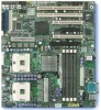
Intel® Server Board SE7320SP2 Layout Revision 4.0 3 Each connector and major component is identified by number and identified in Table 1. 11 19 14 15 10 13 12 1 8 9 8 7 1 17 6 5 2 1 4 3 1 Figure 1. Intel® Server Boards SE7320SP2 and SE7525GP2 Server Board Overview The following figure shows the board layout of the Intel® Server Board SE7320SP2.
Intel® Server Board SE7320SP2 Layout Revision 4.0 3 Each connector and major component is identified by number and identified in Table 1. 11 19 14 15 10 13 12 1 8 9 8 7 1 17 6 5 2 1 4 3 1 Figure 1. Intel® Server Boards SE7320SP2 and SE7525GP2 Server Board Overview The following figure shows the board layout of the Intel® Server Board SE7320SP2.

Product Specification
Page 16
... connector ƒ Two USB 2.0 ports ƒ Internal I/O connectors / headers ƒ Onboard USB port headers (capable of the Server Board SE7525GP2 is available. Server Board Overview Intel® Server Boards SE7320SP2 and SE7525GP2 Table 1. Intel® Server Board SE7320SP2 Layout Reference Ref # 1 2 3 4 5 6 7 8 9 10 Description Processor sockets DIMM connectors (from left to right 2A, 2B, 1A, 1B) Two...
... connector ƒ Two USB 2.0 ports ƒ Internal I/O connectors / headers ƒ Onboard USB port headers (capable of the Server Board SE7525GP2 is available. Server Board Overview Intel® Server Boards SE7320SP2 and SE7525GP2 Table 1. Intel® Server Board SE7320SP2 Layout Reference Ref # 1 2 3 4 5 6 7 8 9 10 Description Processor sockets DIMM connectors (from left to right 2A, 2B, 1A, 1B) Two...
Product Specification
Page 17
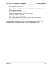
... most FRU devices (processors, memory) ƒ Port-80 diagnostic LEDs displaying POST Codes The following figure shows the board layout of the Intel® Server Board SE7525GP2. Intel® Server Boards SE7320SP2 and SE7525GP2 Server Board Overview ƒ SSI-compliant front panel headers ƒ SSI-compliant 24-pin main power connector (will support ATX-12V...
... most FRU devices (processors, memory) ƒ Port-80 diagnostic LEDs displaying POST Codes The following figure shows the board layout of the Intel® Server Board SE7525GP2. Intel® Server Boards SE7320SP2 and SE7525GP2 Server Board Overview ƒ SSI-compliant front panel headers ƒ SSI-compliant 24-pin main power connector (will support ATX-12V...

Product Specification
Page 18
Intel® Server Board SE7525GP2 Layout 6 Revision 4.0 Server Board Overview 11 19 13 12 1 Intel® Server Boards SE7320SP2 and SE7525GP2 14 15 10 8 9 8 20 7 1 17 6 5 2 1 4 3 1 Figure 2.
Intel® Server Board SE7525GP2 Layout 6 Revision 4.0 Server Board Overview 11 19 13 12 1 Intel® Server Boards SE7320SP2 and SE7525GP2 14 15 10 8 9 8 20 7 1 17 6 5 2 1 4 3 1 Figure 2.

Product Specification
Page 19
Intel® Server Boards SE7320SP2 and SE7525GP2 Server Board Overview Ref # 1 2 3 4 5 6 7 8 9 10 Table 2. Intel® Server Board SE7525GP2 Layout Reference Description Processor sockets Ref # 11 DIMM connectors (from left to right 2A, 2B, 1A, 1B) 12 Two external USB connectors 13 Keyboard and ...
Intel® Server Boards SE7320SP2 and SE7525GP2 Server Board Overview Ref # 1 2 3 4 5 6 7 8 9 10 Table 2. Intel® Server Board SE7525GP2 Layout Reference Description Processor sockets Ref # 11 DIMM connectors (from left to right 2A, 2B, 1A, 1B) 12 Two external USB connectors 13 Keyboard and ...

Product Specification
Page 20
Where appropriate, features that are specific to the similarities between these two products, this chapter discusses all features that make up the server boards. Functional Architecture This chapter provides a high-level description of the functionality associated with the architectural blocks that are present on both products. Note: Due to one product or the other will noted. Functional Architecture Intel® Server Boards SE7320SP2 and SE7525GP2 3. Figure 3. Intel® Server Board SE7320SP2 Block Diagram 8 Revision 4.0
Where appropriate, features that are specific to the similarities between these two products, this chapter discusses all features that make up the server boards. Functional Architecture This chapter provides a high-level description of the functionality associated with the architectural blocks that are present on both products. Note: Due to one product or the other will noted. Functional Architecture Intel® Server Boards SE7320SP2 and SE7525GP2 3. Figure 3. Intel® Server Board SE7320SP2 Block Diagram 8 Revision 4.0

Product Specification
Page 21
Intel® Server Board SE7525GP2 Block Diagram 3.1 Processor Sub-system The support circuitry for the processor sub-system consists of the following: ƒ Dual 604-pin zero insertion force (ZIF) processor sockets ƒ Processor host bus AGTL+ support circuitry ƒ Reset configuration logic ƒ Processor module presence detection logic ƒ BSEL detection capabilities ƒ CPU signal level translation ƒ Common enabling kit (CEK) CPU retention support Revision 4.0 9 Intel® Server Boards SE7320SP2 and SE7525GP2 Functional Architecture Figure 4.
Intel® Server Board SE7525GP2 Block Diagram 3.1 Processor Sub-system The support circuitry for the processor sub-system consists of the following: ƒ Dual 604-pin zero insertion force (ZIF) processor sockets ƒ Processor host bus AGTL+ support circuitry ƒ Reset configuration logic ƒ Processor module presence detection logic ƒ BSEL detection capabilities ƒ CPU signal level translation ƒ Common enabling kit (CEK) CPU retention support Revision 4.0 9 Intel® Server Boards SE7320SP2 and SE7525GP2 Functional Architecture Figure 4.