Product Specification
Page 2
...Disclaimers Information in this document or any patent, copyright or other intellectual property right. Revision History Intel® Server Boards SE7320SP2 and SE7525GP2 Revision History Date June 2004 November 2004 September 2005 December 2005 Revision Number Modifications 1.0 Initial Release ...description, updated the function introduction of any software that may appear in this document. Updated supported processors matrix and BIOS setup options according to specifications and product descriptions at any features or instructions marked "reserved" or "undefined." ...
...Disclaimers Information in this document or any patent, copyright or other intellectual property right. Revision History Intel® Server Boards SE7320SP2 and SE7525GP2 Revision History Date June 2004 November 2004 September 2005 December 2005 Revision Number Modifications 1.0 Initial Release ...description, updated the function introduction of any software that may appear in this document. Updated supported processors matrix and BIOS setup options according to specifications and product descriptions at any features or instructions marked "reserved" or "undefined." ...
Product Specification
Page 5
Platform Management...95 5.1.1 5V Standby ...97 5.1.2 IPMI Messaging, Commands, and Abstractions 97 5.1.3 IPMI Sensor Model 98 Revision 4.0 v Intel® Server Boards SE7320SP2 and SE7525GP2 Contents 4.3.3 Configuration Reset 60 4.3.4 Keyboard Commands 61 4.4 Entering BIOS Setup 62 4.4.1 Main Menu ...62 4.4.2 Advanced Menu...63 4.4.3 Boot Menu ...73 4.4.4 Security Menu...75 4.4.5 Server Menu ...76 4.4.6 Exit Menu...81 4.5 Flash...
Platform Management...95 5.1.1 5V Standby ...97 5.1.2 IPMI Messaging, Commands, and Abstractions 97 5.1.3 IPMI Sensor Model 98 Revision 4.0 v Intel® Server Boards SE7320SP2 and SE7525GP2 Contents 4.3.3 Configuration Reset 60 4.3.4 Keyboard Commands 61 4.4 Entering BIOS Setup 62 4.4.1 Main Menu ...62 4.4.2 Advanced Menu...63 4.4.3 Boot Menu ...73 4.4.4 Security Menu...75 4.4.5 Server Menu ...76 4.4.6 Exit Menu...81 4.5 Flash...

Product Specification
Page 7
... 7.15.3 SCSI LED Header 158 7.16 Configuration Jumpers 159 7.16.1 System Recovery and Update Jumpers 159 7.16.2 Rolling BIOS Bank Selection Jumper 160 8. Intel® Server Boards SE7320SP2 and SE7525GP2 Contents 6.3 Checkpoints ...133 6.3.1 System ROM BIOS POST Task Test Point (Port 80h Code 133 6.3.2 Diagnostic LEDs 133 6.3.3 POST Code Checkpoints 135 6.3.4 Bootblock Initialization Code...
... 7.15.3 SCSI LED Header 158 7.16 Configuration Jumpers 159 7.16.1 System Recovery and Update Jumpers 159 7.16.2 Rolling BIOS Bank Selection Jumper 160 8. Intel® Server Boards SE7320SP2 and SE7525GP2 Contents 6.3 Checkpoints ...133 6.3.1 System ROM BIOS POST Task Test Point (Port 80h Code 133 6.3.2 Diagnostic LEDs 133 6.3.3 POST Code Checkpoints 135 6.3.4 Bootblock Initialization Code...
Product Specification
Page 9
...Table 41 Table 16. Interrupt Definitions...33 Table 13. Intel® Server Boards SE7320SP2 and SE7525GP2 Contents Figure 15. External Interfaces to mBMC 102 Figure 16. System Configuration Jumpers (J17 159 Figure 20. BIOS Bank Jumper (J26 160 Figure 21. Output Voltage Timing... 163 Figure 22. Intel® Server Board SE7320SP2 Layout Reference 4 Table 2. Intel® Server Board SE7525GP2 Layout Reference 7 Table 3. Processor Support Matrix 12 Table...
...Table 41 Table 16. Interrupt Definitions...33 Table 13. Intel® Server Boards SE7320SP2 and SE7525GP2 Contents Figure 15. External Interfaces to mBMC 102 Figure 16. System Configuration Jumpers (J17 159 Figure 20. BIOS Bank Jumper (J26 160 Figure 21. Output Voltage Timing... 163 Figure 22. Intel® Server Board SE7320SP2 Layout Reference 4 Table 2. Intel® Server Board SE7525GP2 Layout Reference 7 Table 3. Processor Support Matrix 12 Table...
Product Specification
Page 10
... 51. Chassis ID LEDs...118 Table 56. Contents Intel® Server Boards SE7320SP2 and SE7525GP2 Table 23. BIOS Setup IDE Configuration Menu Options 65 Table 26. BIOS Setup, Floppy Configuration Sub-menu Selections 68 Table 29. BIOS Setup, USB Configuration Sub-menu Selections 69 Table 31. BIOS Setup, PCI Configuration Sub-menu Selections 71 Table 33...
... 51. Chassis ID LEDs...118 Table 56. Contents Intel® Server Boards SE7320SP2 and SE7525GP2 Table 23. BIOS Setup IDE Configuration Menu Options 65 Table 26. BIOS Setup, Floppy Configuration Sub-menu Selections 68 Table 29. BIOS Setup, USB Configuration Sub-menu Selections 69 Table 31. BIOS Setup, PCI Configuration Sub-menu Selections 71 Table 33...

Product Specification
Page 11
...-out (J41, J43 153 Table 86. Optional USB Connection Header Pin-out (J31 154 Table 89. Intel® Server Boards SE7320SP2 and SE7525GP2 Contents Table 58. POST Error Messages and Handling 129 Table 61. Troubleshooting BIOS Beep Codes 132 Table 64. P32-A 5V 32-bit/33-MHz PCI Slot Pin-out (J10, J11...
...-out (J41, J43 153 Table 86. Optional USB Connection Header Pin-out (J31 154 Table 89. Intel® Server Boards SE7320SP2 and SE7525GP2 Contents Table 58. POST Error Messages and Handling 129 Table 61. Troubleshooting BIOS Beep Codes 132 Table 64. P32-A 5V 32-bit/33-MHz PCI Slot Pin-out (J10, J11...

Product Specification
Page 12
...105. SCSI LED Header Pin-out (J26 158 Table 97. BIOS Bank Jumper Option 160 Table 99. Power Supply Voltage Specification 162 Table 103. Contents Intel® Server Boards SE7320SP2 and SE7525GP2 Table 93. Absolute Maximum Ratings 161 Table 100. Transient Load ...Requirements 166 xii Revision 4.0 Intel® Xeon® Processor DP TDP Guidelines 162 Table 102....
...105. SCSI LED Header Pin-out (J26 158 Table 97. BIOS Bank Jumper Option 160 Table 99. Power Supply Voltage Specification 162 Table 103. Contents Intel® Server Boards SE7320SP2 and SE7525GP2 Table 93. Absolute Maximum Ratings 161 Table 100. Transient Load ...Requirements 166 xii Revision 4.0 Intel® Xeon® Processor DP TDP Guidelines 162 Table 102....

Product Specification
Page 13
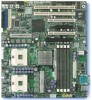
... the following chapters ƒ Chapter 1: Introduction ƒ Chapter 2: Server Board Overview ƒ Chapter 3: Functional Architecture ƒ Chapter 4: System BIOS ƒ Chapter 5: Platform Management ƒ Chapter 6: Error Reporting and Handling ƒ Chapter 7: Connector Definitions and Pin-outs ƒ Chapter... audience for their published operating or non-operating limits. Intel® Server Boards SE7320SP2 and SE7525GP2 Introduction 1. Intel ensures through its own chassis development and testing that when Intel server building blocks are used outside any of high-density...
... the following chapters ƒ Chapter 1: Introduction ƒ Chapter 2: Server Board Overview ƒ Chapter 3: Functional Architecture ƒ Chapter 4: System BIOS ƒ Chapter 5: Platform Management ƒ Chapter 6: Error Reporting and Handling ƒ Chapter 7: Connector Definitions and Pin-outs ƒ Chapter... audience for their published operating or non-operating limits. Intel® Server Boards SE7320SP2 and SE7525GP2 Introduction 1. Intel ensures through its own chassis development and testing that when Intel server building blocks are used outside any of high-density...

Product Specification
Page 22
...higher speed. 3.1.3 Processor Module Presence Detection The server boards provide logic to detect the presence and identity of installed processors. Functional Architecture Intel® Server Boards SE7320SP2 and SE7525GP2 3.1.1 Processor Voltage Regulator Devices (VRDs) The server board has two voltage regulator devices (VRDs) that require up to a sustained .... No mixing of product families is a sustained maximum of a 105 amps and peak support of 120 amps. 3.1.2 Reset Configuration Logic The BIOS determines the processor stepping, cache size, etc through the CPUID instruction.
...higher speed. 3.1.3 Processor Module Presence Detection The server boards provide logic to detect the presence and identity of installed processors. Functional Architecture Intel® Server Boards SE7320SP2 and SE7525GP2 3.1.1 Processor Voltage Regulator Devices (VRDs) The server board has two voltage regulator devices (VRDs) that require up to a sustained .... No mixing of product families is a sustained maximum of a 105 amps and peak support of 120 amps. 3.1.2 Reset Configuration Logic The BIOS determines the processor stepping, cache size, etc through the CPUID instruction.
Product Specification
Page 24
... Functional Architecture Intel® Server Boards SE7320SP2 and SE7525GP2 3.1.6 Processor Support The server boards are not supported. Processor Support Matrix Processor Family Intel® Xeon® Intel Xeon Intel Xeon Intel Xeon Intel Xeon Intel Xeon Intel Xeon Intel Xeon Intel Xeon FSB ...Frequency 533 MHz 533 MHz 533 MHz 800 MHz 800 MHz 800 MHz 800 MHz 800 MHz 800 MHz Frequency 2.8 GHz 3.06 GHz 3.2 GHz 2.8 GHz 3.0 GHz 3.2 GHz 3.4 GHz 3.6 GHz 3.8 GHz Support No No No Yes Yes Yes Yes Yes Yes Note: The latest BIOS...
... Functional Architecture Intel® Server Boards SE7320SP2 and SE7525GP2 3.1.6 Processor Support The server boards are not supported. Processor Support Matrix Processor Family Intel® Xeon® Intel Xeon Intel Xeon Intel Xeon Intel Xeon Intel Xeon Intel Xeon Intel Xeon Intel Xeon FSB ...Frequency 533 MHz 533 MHz 533 MHz 800 MHz 800 MHz 800 MHz 800 MHz 800 MHz 800 MHz Frequency 2.8 GHz 3.06 GHz 3.2 GHz 2.8 GHz 3.0 GHz 3.2 GHz 3.4 GHz 3.6 GHz 3.8 GHz Support No No No Yes Yes Yes Yes Yes Yes Note: The latest BIOS...
Product Specification
Page 25
... mixed cache sizes, error 8192 will be mixed in a system provided that works for storing the update in a system. The BIOS supports variable size microcode updates. Intel® Server Boards SE7320SP2 and SE7525GP2 Functional Architecture 3.1.6.2 Mixed Processor Steppings For optimum system performance, only identical processors should be mixed in a system. If this condition...
... mixed cache sizes, error 8192 will be mixed in a system provided that works for storing the update in a system. The BIOS supports variable size microcode updates. Intel® Server Boards SE7320SP2 and SE7525GP2 Functional Architecture 3.1.6.2 Mixed Processor Steppings For optimum system performance, only identical processors should be mixed in a system. If this condition...
Product Specification
Page 26
...® Technology. All APs execute a halt instruction with the TM1 or TM2 feature. Functional Architecture Intel® Server Boards SE7320SP2 and SE7525GP2 3.1.6.9 Hyper-Threading Technology Intel® Xeon® processors support Hyper-Threading Technology. The BIOS Setup utility provides an option to accept local interrupts (INTR driven by the hardware as an application processor...
...® Technology. All APs execute a halt instruction with the TM1 or TM2 feature. Functional Architecture Intel® Server Boards SE7320SP2 and SE7525GP2 3.1.6.9 Hyper-Threading Technology Intel® Xeon® processors support Hyper-Threading Technology. The BIOS Setup utility provides an option to accept local interrupts (INTR driven by the hardware as an application processor...

Product Specification
Page 35
... Memory List on the support website for a list of supported memory: http://support.intel.com/support/motherboards/server/se7320sp2 http://support.intel.com/support/motherboards/server/se7525gp2 The BIOS reads the Serial Presence Detect (SPD) SEEPROMs on Server Board SE7320SP2 and Server Board SE7525GP2. Otherwise, go to be treated as a bank. Otherwise, memory configuration error.
... Memory List on the support website for a list of supported memory: http://support.intel.com/support/motherboards/server/se7320sp2 http://support.intel.com/support/motherboards/server/se7525gp2 The BIOS reads the Serial Presence Detect (SPD) SEEPROMs on Server Board SE7320SP2 and Server Board SE7525GP2. Otherwise, go to be treated as a bank. Otherwise, memory configuration error.
Product Specification
Page 37
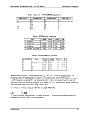
... program the MCH memory registers. Possible Memory Capacities # of unused memory above the 4 GB address, but this memory is not be accessible for BIOS, APIC configuration space, PCI adapter interface, and virtual video memory space. The chipset should allow the remapping of DIMMS 1 2 2 4 4... 8 GB 1 Gb 2 GB 4 GB 8 GB 8 GB Note: Memory between 4 GB and 4 GB minus 512 MB is usable. Intel® Server Boards SE7320SP2 and SE7525GP2 Functional Architecture Table 5. Revision 4.0 25 DIMM Module Capacities Parts X8, single row X8, double row X4, single row X4, Stacked, double row...
... program the MCH memory registers. Possible Memory Capacities # of unused memory above the 4 GB address, but this memory is not be accessible for BIOS, APIC configuration space, PCI adapter interface, and virtual video memory space. The chipset should allow the remapping of DIMMS 1 2 2 4 4... 8 GB 1 Gb 2 GB 4 GB 8 GB 8 GB Note: Memory between 4 GB and 4 GB minus 512 MB is usable. Intel® Server Boards SE7320SP2 and SE7525GP2 Functional Architecture Table 5. Revision 4.0 25 DIMM Module Capacities Parts X8, single row X8, double row X4, single row X4, Stacked, double row...
Product Specification
Page 38
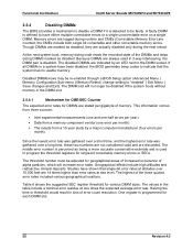
... in loss of the three quoted error rates included various geographical locations. Functional Architecture Intel® Server Boards SE7320SP2 and SE7525GP2 3.5.4 Disabling DIMMs The BIOS provides a mechanism to disable a DIMM if it is detected to be re-enabled through a BIOS Setup option (Advanced Menu | Memory Configuration Sub-menu | Memory Retest | change setting to "enabled...
... in loss of the three quoted error rates included various geographical locations. Functional Architecture Intel® Server Boards SE7320SP2 and SE7525GP2 3.5.4 Disabling DIMMs The BIOS provides a mechanism to disable a DIMM if it is detected to be re-enabled through a BIOS Setup option (Advanced Menu | Memory Configuration Sub-menu | Memory Retest | change setting to "enabled...

Product Specification
Page 39
...08h, then the DIMM 1A LED will be lit and the CME logging and detection will be disabled by BIOS. 3.5.5 Memory RASUM Features The Intel® E7320 MCH and Intel E7525 MCH support several memory RASUM (Reliability, Availability, Serviceability, Usability, and Manageability) features that have traditionally ..., and DIMM Sparing. The counter for memory error detection and correction, Memory Scrubbing, Retry on these server boards. Intel® Server Boards SE7320SP2 and SE7525GP2 Functional Architecture Table 8. The following sections describe how each individual DIMM.
...08h, then the DIMM 1A LED will be lit and the CME logging and detection will be disabled by BIOS. 3.5.5 Memory RASUM Features The Intel® E7320 MCH and Intel E7525 MCH support several memory RASUM (Reliability, Availability, Serviceability, Usability, and Manageability) features that have traditionally ..., and DIMM Sparing. The counter for memory error detection and correction, Memory Scrubbing, Retry on these server boards. Intel® Server Boards SE7320SP2 and SE7525GP2 Functional Architecture Table 8. The following sections describe how each individual DIMM.

Product Specification
Page 41
...on any given read request will be removed from service. This function facilitates a limited, very high speed memory test, and provides a BIOS-accessible memory zeroing capability for use by the operating system. 3.5.5.5 DIMM Sparing Function To provide a more complex. This RASUM feature may... software, so it is repeated it and its corresponding partner in the other machine initialization and configuration tasks. Intel® Server Boards SE7320SP2 and SE7525GP2 Functional Architecture Note that will never be reached by a "healthy" memory subsystem experiencing the rate of errors ...
...on any given read request will be removed from service. This function facilitates a limited, very high speed memory test, and provides a BIOS-accessible memory zeroing capability for use by the operating system. 3.5.5.5 DIMM Sparing Function To provide a more complex. This RASUM feature may... software, so it is repeated it and its corresponding partner in the other machine initialization and configuration tasks. Intel® Server Boards SE7320SP2 and SE7525GP2 Functional Architecture Note that will never be reached by a "healthy" memory subsystem experiencing the rate of errors ...

Product Specification
Page 43
... resources will support the INT 1Ah PCI BIOS interface calls. 3.6.1.7 Automatic IRQ Assignment The BIOS automatically assigns IRQs to match the behavior of x4 (2 GB/s). 3.6.1.4 P64-Express16: x16 PCI Express bus segment Intel® Server Board SE7525GP2 only: The P64-Express16 bus segment supports... x16 PCI Express signaling. 3.6.1.5 Scan Order The BIOS assigns PCI bus numbers in a depth-first hierarchy, in exception of supported...
... resources will support the INT 1Ah PCI BIOS interface calls. 3.6.1.7 Automatic IRQ Assignment The BIOS automatically assigns IRQs to match the behavior of x4 (2 GB/s). 3.6.1.4 P64-Express16: x16 PCI Express bus segment Intel® Server Board SE7525GP2 only: The P64-Express16 bus segment supports... x16 PCI Express signaling. 3.6.1.5 Scan Order The BIOS assigns PCI bus numbers in a depth-first hierarchy, in exception of supported...
Product Specification
Page 44
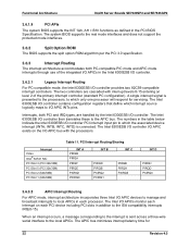
... APIC bus minimizes interrupt latency time for servicing. Functional Architecture Intel® Server Boards SE7320SP2 and SE7525GP2 3.6.1.9 PCI APIs The system BIOS supports the INT 1Ah, AH = B1h functions as defined in the Intel 6300ESB I/O controller. 3.6.3.1 Legacy Interrupt Routing For PC-compatible mode, the Intel 6300ESB I/O controller provides two 82C59-compatible interrupt controllers. The two...
... APIC bus minimizes interrupt latency time for servicing. Functional Architecture Intel® Server Boards SE7320SP2 and SE7525GP2 3.6.1.9 PCI APIs The system BIOS supports the INT 1Ah, AH = B1h functions as defined in the Intel 6300ESB I/O controller. 3.6.3.1 Legacy Interrupt Routing For PC-compatible mode, the Intel 6300ESB I/O controller provides two 82C59-compatible interrupt controllers. The two...

Product Specification
Page 48
.... When sharing is enabled, all decode of up to indicate that the operating system can use PIO mode, but the BIOS will program the necessary Ultra DMA registers in combined mode. The host software follows existing standards and conventions when accessing the ... 40-pin IDE connector on the IDE cable to support different operating system conditions. Functional Architecture Intel® Server Boards SE7320SP2 and SE7525GP2 3.6.4 IDE Support Integrated IDE controllers of the Intel® 6300ESB I/O controller provide two independent IDE channels, each capable of UDMA mode settings. ...
.... When sharing is enabled, all decode of up to indicate that the operating system can use PIO mode, but the BIOS will program the necessary Ultra DMA registers in combined mode. The host software follows existing standards and conventions when accessing the ... 40-pin IDE connector on the IDE cable to support different operating system conditions. Functional Architecture Intel® Server Boards SE7320SP2 and SE7525GP2 3.6.4 IDE Support Integrated IDE controllers of the Intel® 6300ESB I/O controller provide two independent IDE channels, each capable of UDMA mode settings. ...


