User Guide
Page 13
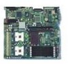
... Error Beep Codes 49 Error Beep Codes Provided by Intel® Management Modules 49 Product Certification Markings 52 Intel® Server Board SE7520JR2 User Guide xiii Contents Figures Figure 1. Configuration Jumper Location 19 Figure 4. Table 5. Intel® Server Board SE7520JR2 15 Figure 2. Password Recovery Jumper 37 Figure 13. Table 2. Opening Socket Lever 28 Figure 7. Installing Memory...26 Figure 6. Inserting Processor...
... Error Beep Codes 49 Error Beep Codes Provided by Intel® Management Modules 49 Product Certification Markings 52 Intel® Server Board SE7520JR2 User Guide xiii Contents Figures Figure 1. Configuration Jumper Location 19 Figure 4. Table 5. Intel® Server Board SE7520JR2 15 Figure 2. Password Recovery Jumper 37 Figure 13. Table 2. Opening Socket Lever 28 Figure 7. Installing Memory...26 Figure 6. Inserting Processor...
User Guide
Page 21
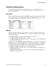
... Software." Processor Support Processor Family FSB Frequency Intel® Xeon™ 800 MHz Intel® Xeon™ 800 MHz Intel® Xeon™ 800 MHz Intel® Xeon™ 800 MHz Intel® Xeon™ 800 MHz Frequency 2.8 GHz 3.0 GHz 3.2 GHz 3.4 GHz 3.6 GHz Memory The Server Board SE7520JR2 provides six DIMM sockets across two channels, Channel A and Channel B. Channel...
... Software." Processor Support Processor Family FSB Frequency Intel® Xeon™ 800 MHz Intel® Xeon™ 800 MHz Intel® Xeon™ 800 MHz Intel® Xeon™ 800 MHz Intel® Xeon™ 800 MHz Frequency 2.8 GHz 3.0 GHz 3.2 GHz 3.4 GHz 3.6 GHz Memory The Server Board SE7520JR2 provides six DIMM sockets across two channels, Channel A and Channel B. Channel...
User Guide
Page 23
... is used with identical singleranked DIMMs in Banks 2 and 3. When all of the Server Board SE7520JR2 that channel. ✏ NOTE Memory mirroring and memory sparing are used as the memory spare. Intel® Server Board SE7520JR2 User Guide 23 If the DIMM in socket 1A fails, the DIMM in that channel. Only one DIMM per channel is copied...
... is used with identical singleranked DIMMs in Banks 2 and 3. When all of the Server Board SE7520JR2 that channel. ✏ NOTE Memory mirroring and memory sparing are used as the memory spare. Intel® Server Board SE7520JR2 User Guide 23 If the DIMM in socket 1A fails, the DIMM in that channel. Only one DIMM per channel is copied...
User Guide
Page 25
... options. DDR DIMMs will not physically fit into a server board designed to support DDR2 DIMMs. DDR2 DIMMs will not physically fit into a server board designed to the processor socket. Disconnect the AC power cord from the edge of the board. Intel® Server Board SE7520JR2 User Guide 25 DIMM3A is the socket closest to support DDR DIMMs. Installing DIMMs To install...
... options. DDR DIMMs will not physically fit into a server board designed to support DDR2 DIMMs. DDR2 DIMMs will not physically fit into a server board designed to the processor socket. Disconnect the AC power cord from the edge of the board. Intel® Server Board SE7520JR2 User Guide 25 DIMM3A is the socket closest to support DDR DIMMs. Installing DIMMs To install...

User Guide
Page 26
... 5. The arrow in the inset in the socket. 9. Position the DIMM above the socket. When the DIMM is inserted, push down on the bottom edge of the DIMM socket(s) are firmly in the DIMM socket. See the documentation that accompanied your server chassis for instructions on installing the server's cover. 26 See the documentation that accompanied...
... 5. The arrow in the inset in the socket. 9. Position the DIMM above the socket. When the DIMM is inserted, push down on the bottom edge of the DIMM socket(s) are firmly in the DIMM socket. See the documentation that accompanied your server chassis for instructions on installing the server's cover. 26 See the documentation that accompanied...
User Guide
Page 27
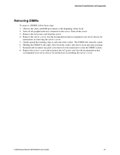
...the DIMM sockets. 8. See the documentation that accompanied your server chassis for instructions on removing the server's cover. 5. Gently spread the retaining clips at the beginning of the socket. Replace the server's cover and reconnect the AC power cord. Intel® Server Board SE7520JR2 User ...Guide 27 Remove the AC power cord from the socket. 6. Remove the server's cover. Observe the safety and ESD precautions at...
...the DIMM sockets. 8. See the documentation that accompanied your server chassis for instructions on removing the server's cover. 5. Gently spread the retaining clips at the beginning of the socket. Replace the server's cover and reconnect the AC power cord. Intel® Server Board SE7520JR2 User ...Guide 27 Remove the AC power cord from the socket. 6. Remove the server's cover. Observe the safety and ESD precautions at...
User Guide
Page 28
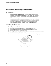
... that is inappropriate for your server. Opening Socket Lever 28 Turn off the server. 3. Remove the server's cover. Hardware Installations and Upgrades Installing or Replacing the Processor CAUTIONS Processor must be appropriate: You may damage the server board if you install a processor that accompanied your server chassis for instructions on removing the server's cover 5. ESD and handling processors...
... that is inappropriate for your server. Opening Socket Lever 28 Turn off the server. 3. Remove the server's cover. Hardware Installations and Upgrades Installing or Replacing the Processor CAUTIONS Processor must be appropriate: You may damage the server board if you install a processor that accompanied your server chassis for instructions on removing the server's cover 5. ESD and handling processors...
User Guide
Page 29
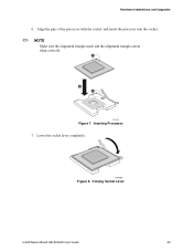
Align the pins of the processor with the socket, and insert the processor into the socket. ✏ NOTE Make sure the alignment triangle mark and the alignment triangle cutout align correctly. Inserting Processor 7. Lower the socket lever completely. A B A TP00764 Figure 7. TP00765 Figure 8. Hardware Installations and Upgrades 6. Closing Socket Lever Intel® Server Board SE7520JR2 User Guide 29
Align the pins of the processor with the socket, and insert the processor into the socket. ✏ NOTE Make sure the alignment triangle mark and the alignment triangle cutout align correctly. Inserting Processor 7. Lower the socket lever completely. A B A TP00764 Figure 7. TP00765 Figure 8. Hardware Installations and Upgrades 6. Closing Socket Lever Intel® Server Board SE7520JR2 User Guide 29

User Guide
Page 30
.... Remove the AC power cord from the processor. See the documentation that accompanied your server chassis for instructions on the corners of this book. 2. Do not force the heat sink from the server board. 6. Removing a Processor 1. Unplug the processor fan cable from the processor. If... it . Installing Heat Sink 5. Use caution when you unpack the heat sink so you removed or disconnected to reach the processor sockets. 6. Doing so could damage the...
.... Remove the AC power cord from the processor. See the documentation that accompanied your server chassis for instructions on the corners of this book. 2. Do not force the heat sink from the server board. 6. Removing a Processor 1. Unplug the processor fan cable from the processor. If... it . Installing Heat Sink 5. Use caution when you unpack the heat sink so you removed or disconnected to reach the processor sockets. 6. Doing so could damage the...

User Guide
Page 33
... or an equivalent, under the tab in the battery socket. 9. Gently push down on removing the server's cover. 5. Remove the new lithium battery from its socket. See the documentation that accompanied your server chassis for instructions on the screwdriver to observe the correct... the battery from the server. 4. Remove the server's cover and locate the battery. Replacing the Backup Battery 7. Run Setup to restore the configuration settings to the server. Turn off all peripheral devices connected to the RTC. Intel® Server Board SE7520JR2 User Guide 33 Hardware ...
... or an equivalent, under the tab in the battery socket. 9. Gently push down on removing the server's cover. 5. Remove the new lithium battery from its socket. See the documentation that accompanied your server chassis for instructions on the screwdriver to observe the correct... the battery from the server. 4. Remove the server's cover and locate the battery. Replacing the Backup Battery 7. Run Setup to restore the configuration settings to the server. Turn off all peripheral devices connected to the RTC. Intel® Server Board SE7520JR2 User Guide 33 Hardware ...

User Guide
Page 40
...power available at the AC source. ‰ Are all cables correctly connected and secured? ‰ Are the processors fully seated in their sockets on the server board? ‰ Are all standoffs in the proper location and not touching any components, causing a potential short? ‰ Are all add-in ...PCI boards fully seated in their slots on the server board? ‰ Are all jumper settings on add-in Setup correct? ‰ Is the operating system properly loaded? To check ...
...power available at the AC source. ‰ Are all cables correctly connected and secured? ‰ Are the processors fully seated in their sockets on the server board? ‰ Are all standoffs in the proper location and not touching any components, causing a potential short? ‰ Are all add-in ...PCI boards fully seated in their slots on the server board? ‰ Are all jumper settings on add-in Setup correct? ‰ Is the operating system properly loaded? To check ...

User Guide
Page 44
...sockets the wrong way? If not, see "Power Light Does Not Light" ‰ If your fans speeded up in response to "Enabled." If so, the signal cable may be plugged in diskette controller, make sure that has failed? ‰ Are the fan power connectors properly connected to the server board...? ‰ Is the cable from the control panel board connected to the both the control panel board and to the server board? ‰ Are the power supply cables properly connected to the server board? ‰ Are there any of the fan motors ...
...sockets the wrong way? If not, see "Power Light Does Not Light" ‰ If your fans speeded up in response to "Enabled." If so, the signal cable may be plugged in diskette controller, make sure that has failed? ‰ Are the fan power connectors properly connected to the server board...? ‰ Is the cable from the control panel board connected to the both the control panel board and to the server board? ‰ Are the power supply cables properly connected to the server board? ‰ Are there any of the fan motors ...

User Guide
Page 48
... of these LEDs with a description of board Amber Each LED can aid in server identification from the back panel Visible fault warning Location Control panel and board rear left corner Control panel and board rear left board Amber Amber Control Panel Green Notes Press ... ID System fault Function Aid in troubleshooting your system. Troubleshooting LED Information The Intel® Server Board SE7520JR2 includes LEDs that can be Off, Green, Amber, Red Front center board Amber 1" behind processor socket Front left corner Color Blue Green or Amber ATA drive activity Memory fault 1-6...
... of these LEDs with a description of board Amber Each LED can aid in server identification from the back panel Visible fault warning Location Control panel and board rear left corner Control panel and board rear left board Amber Amber Control Panel Green Notes Press ... ID System fault Function Aid in troubleshooting your system. Troubleshooting LED Information The Intel® Server Board SE7520JR2 includes LEDs that can be Off, Green, Amber, Red Front center board Amber 1" behind processor socket Front left corner Color Blue Green or Amber ATA drive activity Memory fault 1-6...

User Guide
Page 49
...socket is bing used, the server board may be faulty. Reseat the memory or replace the DIMMs with known good modules. 4 - 7 or 9 - 11 Fatal error indicating a possible serious system problem. Error Beep Codes Provided by BIOS beep codes. Reseat or replace the failed processor. Intel® Server Board SE7520JR2... User Guide 49 Please note that not all add-in cards are supported by Intel® Management Modules Beep Code Reason for the beeps and action to reveal...
...socket is bing used, the server board may be faulty. Reseat the memory or replace the DIMMs with known good modules. 4 - 7 or 9 - 11 Fatal error indicating a possible serious system problem. Error Beep Codes Provided by BIOS beep codes. Reseat or replace the failed processor. Intel® Server Board SE7520JR2... User Guide 49 Please note that not all add-in cards are supported by Intel® Management Modules Beep Code Reason for the beeps and action to reveal...

