User Guide
Page 1
Intel® Server Board SE7520BD2 User Guide A Guide for Technically Qualified Assemblers of Intel® Identified Subassemblies/Products Order Number: C51518-007
Intel® Server Board SE7520BD2 User Guide A Guide for Technically Qualified Assemblers of Intel® Identified Subassemblies/Products Order Number: C51518-007

User Guide
Page 2
...to any time, without notice. Intel server boards contain a number of high-density VLSI and power delivery components that chooses not to use Intel developed server building blocks to consult vendor datasheets and operating parameters to determine the amount of Intel products including liability or warranties relating..., life saving, or life sustaining applications or for a particular purpose, merchantability, or infringement of others. Intel may be held responsible if components fail or the server board does not operate correctly when used together. Copyright © 2004 - 2005...
...to any time, without notice. Intel server boards contain a number of high-density VLSI and power delivery components that chooses not to use Intel developed server building blocks to consult vendor datasheets and operating parameters to determine the amount of Intel products including liability or warranties relating..., life saving, or life sustaining applications or for a particular purpose, merchantability, or infringement of others. Intel may be held responsible if components fail or the server board does not operate correctly when used together. Copyright © 2004 - 2005...
User Guide
Page 3
..., and how to add and replace components on the Intel® Server Board SE7520BD2. Intel® Server Board SE7520BD2 User Guide iii These boards have the following product codes: ƒ Product code SE7520BD2 ƒ Product code SE7520BD2SCSI ƒ Product code SE7520BD2V ƒ Product code SE7520BD2SCSID2 ƒ Product code SE7520BD2VD2 ƒ Product code SE7520BD2SATAD2 This manual applies to help...
..., and how to add and replace components on the Intel® Server Board SE7520BD2. Intel® Server Board SE7520BD2 User Guide iii These boards have the following product codes: ƒ Product code SE7520BD2 ƒ Product code SE7520BD2SCSI ƒ Product code SE7520BD2V ƒ Product code SE7520BD2SCSID2 ƒ Product code SE7520BD2VD2 ƒ Product code SE7520BD2SATAD2 This manual applies to help...
User Guide
Page 4
... and Configuration Guide Document Tested Hardware and Operating System List Reference Chassis List iv Preface Product Accessories These server boards are compatible with this product Obtain this document / software Intel® Server Board SE7520BD2 Technical Product Specification Intel® Server Board SE7520BD2 Quick Start User's Guide located in -depth technical information about this product, including BIOS settings and...
... and Configuration Guide Document Tested Hardware and Operating System List Reference Chassis List iv Preface Product Accessories These server boards are compatible with this product Obtain this document / software Intel® Server Board SE7520BD2 Technical Product Specification Intel® Server Board SE7520BD2 Quick Start User's Guide located in -depth technical information about this product, including BIOS settings and...
User Guide
Page 5
...The suitability of your end system product may require additional EMC compliance testing. Warnings Heed safety information: Before working with your local Intel Representative. Intended Uses This product was evaluated as : medical, industrial, telecommunications, NEBS, residential, alarm systems, test equipment, etc...Technology Equipment (ITE), which the product is an FCC Class A device. v For more information please contact your server product, whether you are using a server board with a microprocessor from the same family (or higher) and operating at the same (or higher) speed as ...
...The suitability of your end system product may require additional EMC compliance testing. Warnings Heed safety information: Before working with your local Intel Representative. Intended Uses This product was evaluated as : medical, industrial, telecommunications, NEBS, residential, alarm systems, test equipment, etc...Technology Equipment (ITE), which the product is an FCC Class A device. v For more information please contact your server product, whether you are using a server board with a microprocessor from the same family (or higher) and operating at the same (or higher) speed as ...
User Guide
Page 6
...mtliche Warn- After removing a board from its protective wrapper or from the wall outlet. Gripping the wide sides can grip with the function controlled by wearing an antistatic wrist strap attached to ESD. See also Intel Server Boards and Server Chassis Safety Information on your... fingertips or with the pliers, never the wide sides. Hold boards only by their edges. und Sicherheitshinweise in this document before performing any...
...mtliche Warn- After removing a board from its protective wrapper or from the wall outlet. Gripping the wide sides can grip with the function controlled by wearing an antistatic wrist strap attached to ESD. See also Intel Server Boards and Server Chassis Safety Information on your... fingertips or with the pliers, never the wide sides. Hold boards only by their edges. und Sicherheitshinweise in this document before performing any...
User Guide
Page 9
Contents 1 Server Board Features 13 Connector and Header Locations 18 Product Codes SE7520BD2, SE7520BD2SCSI, SE7520BD2V 18 Product Codes SE7520BD2SCSID2, SE7520BD2VD2, SE7520BD2SATAD2 20 Configuration Jumpers ...22 Back Panel Connectors...23 Hardware Requirements ...24 Server Chassis ...24 Processor ...24 Memory ...25 2 Hardware Installations and Upgrades 28 Before You Begin ...28 Tools and Supplies ... Testing 47 Confirming Loading of the Operating System 48 Specific Problems and Corrective Actions 48 Power Light Does Not Light 48 Intel® Server Board SE7520BD2 User Guide ix
Contents 1 Server Board Features 13 Connector and Header Locations 18 Product Codes SE7520BD2, SE7520BD2SCSI, SE7520BD2V 18 Product Codes SE7520BD2SCSID2, SE7520BD2VD2, SE7520BD2SATAD2 20 Configuration Jumpers ...22 Back Panel Connectors...23 Hardware Requirements ...24 Server Chassis ...24 Processor ...24 Memory ...25 2 Hardware Installations and Upgrades 28 Before You Begin ...28 Tools and Supplies ... Testing 47 Confirming Loading of the Operating System 48 Specific Problems and Corrective Actions 48 Power Light Does Not Light 48 Intel® Server Board SE7520BD2 User Guide ix
User Guide
Page 11
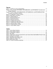
... Figures Figure 1. Inserting Processor...31 Figure 9. Replacing the Backup Battery 36 Figure 12. Server Board Varieties 14 Table 2. Intel® Server Chassis Supported for each Server Board SE7520BD2 Product Code.. 24 Table 6. Product Codes SE7520BD2, SE7520BD2SCSI, and SE7520BD2V Connector and ... Figure 5. Back Panel Connectors 23 Figure 6. Closing Socket Lever 32 Figure 10. Server Board Features 17 Table 3. Product Codes SE7520BD2SCSID2, SE7520BD2VD2, and SE7520BD2SATAD2 Connector and Header Locations 21 Figure 4. Intel® Server Board SE7520BD2 13 Figure 2.
... Figures Figure 1. Inserting Processor...31 Figure 9. Replacing the Backup Battery 36 Figure 12. Server Board Varieties 14 Table 2. Intel® Server Chassis Supported for each Server Board SE7520BD2 Product Code.. 24 Table 6. Product Codes SE7520BD2, SE7520BD2SCSI, and SE7520BD2V Connector and ... Figure 5. Back Panel Connectors 23 Figure 6. Closing Socket Lever 32 Figure 10. Server Board Features 17 Table 3. Product Codes SE7520BD2SCSID2, SE7520BD2VD2, and SE7520BD2SATAD2 Connector and Header Locations 21 Figure 4. Intel® Server Board SE7520BD2 13 Figure 2.
User Guide
Page 13
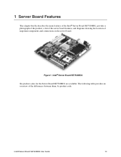
The following table provides an overview of important components and connections on the server board. Figure 1. 1 Server Board Features This chapter briefly describes the main features of the Intel® Server Board SE7520BD2, provides a photograph of the product, a list of the server board features, and diagrams showing the location of the differences between them, by product code. Intel® Server Board SE7520BD2 User Guide 13 Intel® Server Board SE7520BD2 Six product codes for the Server Board SE7520BD2 are available.
The following table provides an overview of important components and connections on the server board. Figure 1. 1 Server Board Features This chapter briefly describes the main features of the Intel® Server Board SE7520BD2, provides a photograph of the product, a list of the server board features, and diagrams showing the location of the differences between them, by product code. Intel® Server Board SE7520BD2 User Guide 13 Intel® Server Board SE7520BD2 Six product codes for the Server Board SE7520BD2 are available.
User Guide
Page 14
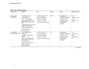
Server Board Varieties Product Code Memory PCI SCSI Product code SE7520BD2 Product code SE7520BD2SATAD2 Six DIMM sockets DDR 266/333 72-bit, 184-pin DIMMs Supported DIMM ... 0 and 1. One IDE connector supporting two ATA/100 IDE channels. Four: - Five: - Three at front of board - Two at rear of board Continued 14 One IDE connector supporting two ATA/100 IDE channels. Two at rear of board Dual serial ATA channels with support for RAID 0 and 1. Two at front of board - Server Board Features Table 1.
Server Board Varieties Product Code Memory PCI SCSI Product code SE7520BD2 Product code SE7520BD2SATAD2 Six DIMM sockets DDR 266/333 72-bit, 184-pin DIMMs Supported DIMM ... 0 and 1. One IDE connector supporting two ATA/100 IDE channels. Four: - Five: - Three at front of board - Two at rear of board Continued 14 One IDE connector supporting two ATA/100 IDE channels. Two at rear of board Dual serial ATA channels with support for RAID 0 and 1. Two at front of board - Server Board Features Table 1.
User Guide
Page 15
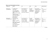
One IDE connector supporting two ATA/100 IDE channels. Four: - Two at rear of board - Three at rear of board - Two at front of board One PCI Express* x8 One PCI Express x4 One PCI-X* 133MHz Two PCI-X 100MHz One PCI 32-bit / ... controller Dual serial ATA channels with support for RAID 0 and 1. Two at front of board Continued 15 Five: - One IDE connector supporting two ATA/100 IDE channels. Server Board Features Table 1. Server Board Varieties (continued) Product Code Memory PCI SCSI SATA USB Connections Product code SE7520BD2SCSI Product code ...
One IDE connector supporting two ATA/100 IDE channels. Four: - Two at rear of board - Three at rear of board - Two at front of board One PCI Express* x8 One PCI Express x4 One PCI-X* 133MHz Two PCI-X 100MHz One PCI 32-bit / ... controller Dual serial ATA channels with support for RAID 0 and 1. Two at front of board Continued 15 Five: - One IDE connector supporting two ATA/100 IDE channels. Server Board Features Table 1. Server Board Varieties (continued) Product Code Memory PCI SCSI SATA USB Connections Product code SE7520BD2SCSI Product code ...
User Guide
Page 16
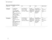
One IDE connector supporting two ATA/100 IDE channels. Four: - Server Board Varieties (continued) Product Code Memory PCI SCSI SATA USB Connections Product code SE7520BD2V Product code SE7520BD2VD2 Six DIMM sockets DDR 266/333 72-bit, 184-pin DIMMs Supported DIMM sizes: 256MB, 512MB, 1GB, 2GB, 4GB 24 GB Maximum (when 4 GB DIMMs ...
One IDE connector supporting two ATA/100 IDE channels. Four: - Server Board Varieties (continued) Product Code Memory PCI SCSI SATA USB Connections Product code SE7520BD2V Product code SE7520BD2VD2 Six DIMM sockets DDR 266/333 72-bit, 184-pin DIMMs Supported DIMM sizes: 256MB, 512MB, 1GB, 2GB, 4GB 24 GB Maximum (when 4 GB DIMMs ...
User Guide
Page 17
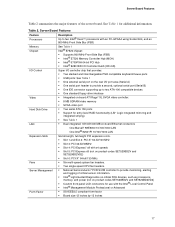
...) ƒ See Table 1 ƒ Dual integrated 10/100/1000 MB on product codes SE7520BD2V and SE7520BD2VD2) ƒ Custom front panel LCD connectors for additional information. Server Board Features Table 2 summarizes the major features of critical sensor information. ƒ Intel® Light-Guided Diagnostics on critical FRU devices, such as processors, memory, and power (not...
...) ƒ See Table 1 ƒ Dual integrated 10/100/1000 MB on product codes SE7520BD2V and SE7520BD2VD2) ƒ Custom front panel LCD connectors for additional information. Server Board Features Table 2 summarizes the major features of critical sensor information. ƒ Intel® Light-Guided Diagnostics on critical FRU devices, such as processors, memory, and power (not...
User Guide
Page 18
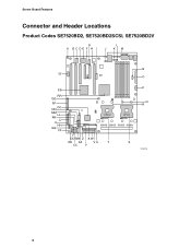
Server Board Features Connector and Header Locations Product Codes SE7520BD2, SE7520BD2SCSI, SE7520BD2V G A BCDE F H I L J KM TT SS RR QQ PP NN OO MM LL KK JJ II HH GG FF CPU 2 DD BB Z X W EE AA VU T CC Y N O P Q R CPU 1 S TP00718 18
Server Board Features Connector and Header Locations Product Codes SE7520BD2, SE7520BD2SCSI, SE7520BD2V G A BCDE F H I L J KM TT SS RR QQ PP NN OO MM LL KK JJ II HH GG FF CPU 2 DD BB Z X W EE AA VU T CC Y N O P Q R CPU 1 S TP00718 18
User Guide
Page 19
Server Board Features A Chassis Intrusion B, Left PCI-X* 100 Slot B, Right PCI-X 100 Slot (MROMB) C Super I/O D PCI Slot 32/33 E ATI* Rage XL Graphics Controller F, Left x8 (x4speed) PCI-Express* Slot F, Right x8 PCI-Express Slot G Intel® 82541P1 (10/100/1000) H PCI-X 133 Slot I Battery P CPU ...Power Connector Q DIMM Sockets R CPU 1 Fan Header S CPU 1 T CPU 2 U Intel® Management Module Connector V IDE Connector W Floppy Connector X System Fan 2 (3-pin) Y System Fan 2 (2-pin) Z System Fan 1 (2-pin) J ICMB Connector K System...
Server Board Features A Chassis Intrusion B, Left PCI-X* 100 Slot B, Right PCI-X 100 Slot (MROMB) C Super I/O D PCI Slot 32/33 E ATI* Rage XL Graphics Controller F, Left x8 (x4speed) PCI-Express* Slot F, Right x8 PCI-Express Slot G Intel® 82541P1 (10/100/1000) H PCI-X 133 Slot I Battery P CPU ...Power Connector Q DIMM Sockets R CPU 1 Fan Header S CPU 1 T CPU 2 U Intel® Management Module Connector V IDE Connector W Floppy Connector X System Fan 2 (3-pin) Y System Fan 2 (2-pin) Z System Fan 1 (2-pin) J ICMB Connector K System...
User Guide
Page 21
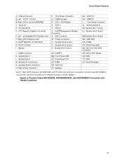
Figure 3. Server Board Features A Chassis Intrusion B, Left PCI-X* 100 Slot B, Right PCI-X 100 Slot (MROMB) C Super I/O D PCI Slot 32/33 E ATI* Rage XL Graphics Controller F, Left x8 (x4speed) PCI-Express* Slot F, Right x8 PCI-Express Slot G Intel® 82541P1 (10/100/1000) H PCI-X 133 Slot I Battery J ICMB Connector K System Fan 5 L ... (SCSI Channel B) are not available on product code SE7520BD2SATAD2. QQ (LSI* 53C1030 SCSI Controller) is not available on product codes SE7520BD2VD2. Product Codes SE7520BD2SCSID2, SE7520BD2VD2, and SE7520BD2SATAD2 Connector and Header Locations 21
Figure 3. Server Board Features A Chassis Intrusion B, Left PCI-X* 100 Slot B, Right PCI-X 100 Slot (MROMB) C Super I/O D PCI Slot 32/33 E ATI* Rage XL Graphics Controller F, Left x8 (x4speed) PCI-Express* Slot F, Right x8 PCI-Express Slot G Intel® 82541P1 (10/100/1000) H PCI-X 133 Slot I Battery J ICMB Connector K System Fan 5 L ... (SCSI Channel B) are not available on product code SE7520BD2SATAD2. QQ (LSI* 53C1030 SCSI Controller) is not available on product codes SE7520BD2VD2. Product Codes SE7520BD2SCSID2, SE7520BD2VD2, and SE7520BD2SATAD2 Connector and Header Locations 21
User Guide
Page 22
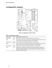
... pins are jumpered, administrator and user passwords will attempt to recover the BIOS by loading the BIOS code into the flash device from a floppy disk. Server Board Features Configuration Jumpers BIOS SEL Normal 3 J1B1 Bank 0 CMOS CLR RECOVERY BOOT J4H1 FRB HALT 3 J2H1 3 J4H3 J4H2 PASSWORD CLEAR TP00723 Figure 4. Configuration Jumpers Jumper...
... pins are jumpered, administrator and user passwords will attempt to recover the BIOS by loading the BIOS code into the flash device from a floppy disk. Server Board Features Configuration Jumpers BIOS SEL Normal 3 J1B1 Bank 0 CMOS CLR RECOVERY BOOT J4H1 FRB HALT 3 J2H1 3 J4H3 J4H2 PASSWORD CLEAR TP00723 Figure 4. Configuration Jumpers Jumper...
User Guide
Page 23
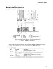
Back Panel Connectors Server Board Features D F H A B CE G A USB3 (see note)* B USB2 C USB1 D Mouse E Keyboard F Serial A I TP00719 G Video H NIC1 (Management port) I NIC2 Note: USB3 is in place Network connection is available ... Description No network connection is in place Transmit/receive activity 10 Mbps connection (if left of the NICs provide the following information. Table 4. See the Intel® Server Board SE7520BD2 Technical Product Specification for POST code errors.
Back Panel Connectors Server Board Features D F H A B CE G A USB3 (see note)* B USB2 C USB1 D Mouse E Keyboard F Serial A I TP00719 G Video H NIC1 (Management port) I NIC2 Note: USB3 is in place Network connection is available ... Description No network connection is in place Transmit/receive activity 10 Mbps connection (if left of the NICs provide the following information. Table 4. See the Intel® Server Board SE7520BD2 Technical Product Specification for POST code errors.
User Guide
Page 24
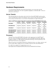
... Supported Supported Supported Not supported Not supported SE7520BD2SATAD2 Supported Supported Supported Supported Supported Supported SE7520BD2SCSID2 Supported Supported Supported Supported Supported Supported SE7520BD2VD2 Supported Supported Supported Supported Supported Supported Processor The Intel® Server Board SE7520BD2 (all product codes) supports up to the complete list of identical revision, core voltage, cache size, and bus/core...
... Supported Supported Supported Not supported Not supported SE7520BD2SATAD2 Supported Supported Supported Supported Supported Supported SE7520BD2SCSID2 Supported Supported Supported Supported Supported Supported SE7520BD2VD2 Supported Supported Supported Supported Supported Supported Processor The Intel® Server Board SE7520BD2 (all product codes) supports up to the complete list of identical revision, core voltage, cache size, and bus/core...
User Guide
Page 25
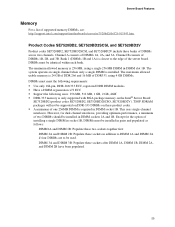
... when only a single DIMM is installed. Bank 1 (DIMMs 1B and 1A) is closest to be supported on DDR-333 DIMMs on the Intel® Server Board SE7520BD2 (product codes SE7520BD2, SE7520BD2SCSO, SE7520BD2V). However, for the option of installing a single DIMM in socket 1B, DIMMs must be identical within... each bank. Channel A consists of the server board. The minimum allowed memory is 256 MB, using 4 GB DIMMs. DIMMs must be installed in pairs and populated as follows: DIMM1A and DIMM 1B...
... when only a single DIMM is installed. Bank 1 (DIMMs 1B and 1A) is closest to be supported on DDR-333 DIMMs on the Intel® Server Board SE7520BD2 (product codes SE7520BD2, SE7520BD2SCSO, SE7520BD2V). However, for the option of installing a single DIMM in socket 1B, DIMMs must be identical within... each bank. Channel A consists of the server board. The minimum allowed memory is 256 MB, using 4 GB DIMMs. DIMMs must be installed in pairs and populated as follows: DIMM1A and DIMM 1B...


