User Guide
Page 2
... create a situation where personal injury or death may be held responsible if components fail or the server board does not operate correctly when used together. Intel server boards contain a number of their specific application and environmental conditions. Intel, Intel Pentium, and Intel Xeon are trademarks or registered trademarks of these components when the fully integrated system is provided...
... create a situation where personal injury or death may be held responsible if components fail or the server board does not operate correctly when used together. Intel server boards contain a number of their specific application and environmental conditions. Intel, Intel Pentium, and Intel Xeon are trademarks or registered trademarks of these components when the fully integrated system is provided...

User Guide
Page 3
... that may be used with the following Intel® Server Chassis: ƒ Intel® Server Chassis SR2400 ƒ Intel® Server Platform SR1435VP2 You may need , troubleshooting information, and instructions on how to add and replace components on the Intel Server Board SE7320VP2. Chapter 3 provides instructions on using the Intel® Server Board SE7320VP2. Intel® Server Board SE7320VP2 User Guide iii Chapter 2 provides instructions on adding and...
... that may be used with the following Intel® Server Chassis: ƒ Intel® Server Chassis SR2400 ƒ Intel® Server Platform SR1435VP2 You may need , troubleshooting information, and instructions on how to add and replace components on the Intel Server Board SE7320VP2. Chapter 3 provides instructions on using the Intel® Server Board SE7320VP2. Intel® Server Board SE7320VP2 User Guide iii Chapter 2 provides instructions on adding and...

User Guide
Page 4
..." (for operating system drivers) For firmware and BIOS updates Search for "Firmware Update" For diagnostics test software Search for "Technical Product Specification" See the Intel® Server Board SE7320VP2 Quick Start User's Guide in -depth technical information about this product, including BIOS settings and chipset information If you need to search "This Product." These...
..." (for operating system drivers) For firmware and BIOS updates Search for "Firmware Update" For diagnostics test software Search for "Technical Product Specification" See the Intel® Server Board SE7320VP2 Quick Start User's Guide in -depth technical information about this product, including BIOS settings and chipset information If you need to search "This Product." These...

User Guide
Page 5
...alarm systems, test equipment, etc.), other than an ITE application, may require additional EMC compliance testing. Integration of your local Intel Representative. v For more information please contact your end system product may require further evaluation EMC Testing Before computer integration, make ... offices, schools, computer rooms, and similar commercial type locations. Preface Safety Information WARNING Before working with your server product, whether you are using a server board with a microprocessor from the same family (or higher) and operating at the same (or higher) speed ...
...alarm systems, test equipment, etc.), other than an ITE application, may require additional EMC compliance testing. Integration of your local Intel Representative. v For more information please contact your end system product may require further evaluation EMC Testing Before computer integration, make ... offices, schools, computer rooms, and similar commercial type locations. Preface Safety Information WARNING Before working with your server product, whether you are using a server board with a microprocessor from the same family (or higher) and operating at the same (or higher) speed ...

User Guide
Page 7
...Beachten Sie hierzu auch die Sicherheitshinweise zu IntelServerplatinen und -Servergehäusen auf der Ressourcen-CD oder unter http://support.intel.com/support/motherboards/server/. Schalten Sie alle an Ihr System angeschlossenen Peripheriegeräte aus. 2. when handling components. 6. A microprocessor ... Gehäuseteile scharfe Spitzen und Kanten aufweisen. Schalten Sie das System mit dem Hauptschalter aus. 3. See also Intel Server Boards and Server Chassis Safety Information on the back of the system, follow these steps: 1. Label and disconnect all caution and ...
...Beachten Sie hierzu auch die Sicherheitshinweise zu IntelServerplatinen und -Servergehäusen auf der Ressourcen-CD oder unter http://support.intel.com/support/motherboards/server/. Schalten Sie alle an Ihr System angeschlossenen Peripheriegeräte aus. 2. when handling components. 6. A microprocessor ... Gehäuseteile scharfe Spitzen und Kanten aufweisen. Schalten Sie das System mit dem Hauptschalter aus. 3. See also Intel Server Boards and Server Chassis Safety Information on the back of the system, follow these steps: 1. Label and disconnect all caution and ...
User Guide
Page 11
Contents Contents 1 Server Board Features 15 Connector and Header Locations 17 Configuration Jumpers ...18 Back Panel Connectors...21 Hardware Requirements ...22 Processor ...22 Memory ...22 Optional Hardware ...24 Storage ... Processor 28 Removing a Processor 30 RJ45 Serial Port Configuration 31 Installing a PCI, PCI-X, or PCI-Express* Add-in Card 32 Replacing the Backup Battery 32 3 Server Utilities 34 Using the BIOS Setup Utility 34 Starting Setup ...34 If You Cannot Access Setup 34 Setup Menus ...34 Upgrading the BIOS ...36 Preparing...
Contents Contents 1 Server Board Features 15 Connector and Header Locations 17 Configuration Jumpers ...18 Back Panel Connectors...21 Hardware Requirements ...22 Processor ...22 Memory ...22 Optional Hardware ...24 Storage ... Processor 28 Removing a Processor 30 RJ45 Serial Port Configuration 31 Installing a PCI, PCI-X, or PCI-Express* Add-in Card 32 Replacing the Backup Battery 32 3 Server Utilities 34 Using the BIOS Setup Utility 34 Starting Setup ...34 If You Cannot Access Setup 34 Setup Menus ...34 Upgrading the BIOS ...36 Preparing...

User Guide
Page 12
... Configuration Jumper Location 19 Figure 5. Opening Socket Lever 28 Figure 9. Password Recovery Jumper 37 Figure 15. Intel® Server Board SE7320VP2 15 Figure 2. BIOS Select Jumper Location 20 Figure 6. Inserting Processor...29 Figure 10. Replacing the Backup ...Bootable CD-ROM Is Not Detected 47 LED Information ...48 Product Regulatory Compliance 49 Product Safety Compliance 49 Product EMC Compliance - Server Board Connector and Header Locations 17 Figure 3. Installing Memory...26 Figure 8. Class A Compliance 49 Certifications / Registrations / Declarations 50...
... Configuration Jumper Location 19 Figure 5. Opening Socket Lever 28 Figure 9. Password Recovery Jumper 37 Figure 15. Intel® Server Board SE7320VP2 15 Figure 2. BIOS Select Jumper Location 20 Figure 6. Inserting Processor...29 Figure 10. Replacing the Backup ...Bootable CD-ROM Is Not Detected 47 LED Information ...48 Product Regulatory Compliance 49 Product Safety Compliance 49 Product EMC Compliance - Server Board Connector and Header Locations 17 Figure 3. Installing Memory...26 Figure 8. Class A Compliance 49 Certifications / Registrations / Declarations 50...

User Guide
Page 13
Table 5. Table 9. Table 3. Table 6. Table 8. Table 10. Tables Table 1. Table 2. Table 4. Table 11. Contents Server Board Features 16 Recovery Jumper [J1H2, J1H3, J1H5 18 Serial Port Configuration Jumper [J8A3 19 BIOS Select Jumper [J1A4 20 NIC LEDs...21 Processor Support 22 Memory Capacity Support 23 Keyboard Commands 35 Keyboard Commands 48 Product Certification Markings 50 Customer Support Telephone Numbers 53 xiii Table 7.
Table 5. Table 9. Table 3. Table 6. Table 8. Table 10. Tables Table 1. Table 2. Table 4. Table 11. Contents Server Board Features 16 Recovery Jumper [J1H2, J1H3, J1H5 18 Serial Port Configuration Jumper [J8A3 19 BIOS Select Jumper [J1A4 20 NIC LEDs...21 Processor Support 22 Memory Capacity Support 23 Keyboard Commands 35 Keyboard Commands 48 Product Certification Markings 50 Customer Support Telephone Numbers 53 xiii Table 7.
User Guide
Page 15
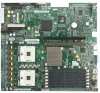
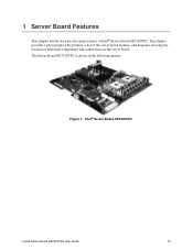
1 Server Board Features This chapter briefly describes the main features of important components and connections on the server board. The Server Board SE7320VP2 is shown in the following picture. Intel® Server Board SE7320VP2 Intel® Server Board SE7320VP2 User Guide 15 This chapter provides a photograph of the product, a list of the server board features, and diagrams showing the location of Intel® Server Board SE7320VP2. Figure 1.
1 Server Board Features This chapter briefly describes the main features of important components and connections on the server board. The Server Board SE7320VP2 is shown in the following picture. Intel® Server Board SE7320VP2 Intel® Server Board SE7320VP2 User Guide 15 This chapter provides a photograph of the product, a list of the server board features, and diagrams showing the location of Intel® Server Board SE7320VP2. Figure 1.
User Guide
Page 16
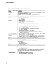
...-pin fan connector to 66 MHz. ƒ One full-height riser connector, utilizing Intel® Adaptive Slot technology. Server Board Features Table 1 summarizes the major features of system fans in the Intel® Server Chassis SR2400 and in PCI, PCI-X, PCIExpress* Cards (riser(s) required) External connections:... ƒ Two IDE channels that is capable of speeds up to two Intel® Xeon™ processors with an 800 MT/s MHz front side bus and frequencies starting at 2.8 GHz. Server Board Features Feature Description Processors Support for 10/100/1000 Mb connections ƒ ...
...-pin fan connector to 66 MHz. ƒ One full-height riser connector, utilizing Intel® Adaptive Slot technology. Server Board Features Table 1 summarizes the major features of system fans in the Intel® Server Chassis SR2400 and in PCI, PCI-X, PCIExpress* Cards (riser(s) required) External connections:... ƒ Two IDE channels that is capable of speeds up to two Intel® Xeon™ processors with an 800 MT/s MHz front side bus and frequencies starting at 2.8 GHz. Server Board Features Feature Description Processors Support for 10/100/1000 Mb connections ƒ ...

User Guide
Page 17
... Header Locations 17 Connector and Header Locations A BC D E CC BB Server Board Features F AA Z G Y X H W V U T SR QP N L J I OM K A Serial Port A header K Processor 2 fan header TP00941 U Configuration jumpers B Battery L +12V processor power connector V SATA 1 connector C Full-height PCI slot M Fan board connector W SATA 0 connector D Low-profile PCI slot N Floppy connector Z Power supply connector E Back panel...
... Header Locations 17 Connector and Header Locations A BC D E CC BB Server Board Features F AA Z G Y X H W V U T SR QP N L J I OM K A Serial Port A header K Processor 2 fan header TP00941 U Configuration jumpers B Battery L +12V processor power connector V SATA 1 connector C Full-height PCI slot M Fan board connector W SATA 0 connector D Low-profile PCI slot N Floppy connector Z Power supply connector E Back panel...

User Guide
Page 18
... Pins What happens at system reset... J1H3: Recovery Boot 1-2 If these pins are jumpered, the CMOS settings will be cleared on the Clear next reset. Server Board Features Configuration Jumpers Recovery Jumpers J1H2, J1H3, J1H5 J1H2 Pass Clr 3 Protect 2 Erase J1H3 Rcvr Boot Recovery Boot 2 Normal Boot 3 J1H5 CMOS Clr 3 BMC Control...
... Pins What happens at system reset... J1H3: Recovery Boot 1-2 If these pins are jumpered, the CMOS settings will be cleared on the Clear next reset. Server Board Features Configuration Jumpers Recovery Jumpers J1H2, J1H3, J1H5 J1H2 Pass Clr 3 Protect 2 Erase J1H3 Rcvr Boot Recovery Boot 2 Normal Boot 3 J1H5 CMOS Clr 3 BMC Control...

User Guide
Page 19
Serial Port Configuration Jumper [J8A3] Pins What happens at system reset... 1-3 Serial port is configured for DCD to DTR (default) 2-4 Serial port is configured for DSR to DTR 2 TP00944 Figure 4. Serial Port Configuration Jumper Location Table 3. Server Board Features Serial Port Configuration Jumper J8A3 34 1-3: DCD to DTR (Default) 2-4: DSR to DTR. 19
Serial Port Configuration Jumper [J8A3] Pins What happens at system reset... 1-3 Serial port is configured for DCD to DTR (default) 2-4 Serial port is configured for DSR to DTR 2 TP00944 Figure 4. Serial Port Configuration Jumper Location Table 3. Server Board Features Serial Port Configuration Jumper J8A3 34 1-3: DCD to DTR (Default) 2-4: DSR to DTR. 19

User Guide
Page 20
Server Board Features BIOS Select Jumper J1A4 BIOS Select 1-2: Normal Operation (Default) 3 2-3: Force to lower bank 20 BIOS Select Jumper [J1A4] Pins What happens at system reset... 1-2 System is configured for normal operation 2-3 Force BIOS to 3 Lower Bank TP00949 Figure 5. BIOS Select Jumper Location Table 4.
Server Board Features BIOS Select Jumper J1A4 BIOS Select 1-2: Normal Operation (Default) 3 2-3: Force to lower bank 20 BIOS Select Jumper [J1A4] Pins What happens at system reset... 1-2 System is configured for normal operation 2-3 Force BIOS to 3 Lower Bank TP00949 Figure 5. BIOS Select Jumper Location Table 4.

User Guide
Page 21
Table 5. NIC LEDs LED Color LED State Off Left LED Solid Amber Blinking Amber Off Right LED Solid Amber Solid Green Description No network connection Network connection in place Transmit/receive activity 10 Mbps connection (if left of each NIC provide the following information. Back Panel Connectors H TP00943 The NIC LEDs at the right and left LED is on or blinking) 100 Mbps connection 1000 Mbps connection 21 Back Panel Connectors Server Board Features A B C D E F G A Mouse B Keyboard C Serial Port B D NIC1 (1 Gb) E NIC2 (1 Gb) F Video G USB1 H USB2 Figure 6.
Table 5. NIC LEDs LED Color LED State Off Left LED Solid Amber Blinking Amber Off Right LED Solid Amber Solid Green Description No network connection Network connection in place Transmit/receive activity 10 Mbps connection (if left of each NIC provide the following information. Back Panel Connectors H TP00943 The NIC LEDs at the right and left LED is on or blinking) 100 Mbps connection 1000 Mbps connection 21 Back Panel Connectors Server Board Features A B C D E F G A Mouse B Keyboard C Serial Port B D NIC1 (1 Gb) E NIC2 (1 Gb) F Video G USB1 H USB2 Figure 6.
User Guide
Page 22
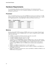
Server Board Features Hardware Requirements To avoid integration difficulties and possible board damage, your system must be installed in pairs and populated as follows: ƒ DIMM1A and DIMM 1B: Populate these two sockets together ...Software." Processor Support Processor Family FSB Frequency Intel® Xeon™ 800 MHz Intel® Xeon™ 800 MHz Intel® Xeon™ 800 MHz Intel® Xeon™ 800 MHz Intel® Xeon™ 800 MHz Frequency 2.8 GHz 3.0 GHz 3.2 GHz 3.4 GHz 3.6 GHz Memory The Server Board SE7320VP2 provides six DIMM sockets across two channels...
Server Board Features Hardware Requirements To avoid integration difficulties and possible board damage, your system must be installed in pairs and populated as follows: ƒ DIMM1A and DIMM 1B: Populate these two sockets together ...Software." Processor Support Processor Family FSB Frequency Intel® Xeon™ 800 MHz Intel® Xeon™ 800 MHz Intel® Xeon™ 800 MHz Intel® Xeon™ 800 MHz Intel® Xeon™ 800 MHz Frequency 2.8 GHz 3.0 GHz 3.2 GHz 3.4 GHz 3.6 GHz Memory The Server Board SE7320VP2 provides six DIMM sockets across two channels...

User Guide
Page 23
... be mixed on -line sparing. For a complete list of all data in the memory subsystem. Memory Sparing and Mirroring The Intel® E7320 chipset supports memory mirroring and memory on the server board, but when mixing DIMM types, DDR333 memory will not fail due to prevent data loss in the opposite channel. With...
... be mixed on -line sparing. For a complete list of all data in the memory subsystem. Memory Sparing and Mirroring The Intel® E7320 chipset supports memory mirroring and memory on the server board, but when mixing DIMM types, DDR333 memory will not fail due to prevent data loss in the opposite channel. With...

User Guide
Page 24
... ATA connection supports one can be used , the spare DIMMs must provide a minimum of 1.2 A of 5 V standby current or the board will not boot. When all installed components. Refer to the Intel® Server Board SE7320VP2 Technical Product Specification for additional drive information and drive installation instructions. 24 A floppy drive connection is removed from service and...
... ATA connection supports one can be used , the spare DIMMs must provide a minimum of 1.2 A of 5 V standby current or the board will not boot. When all installed components. Refer to the Intel® Server Board SE7320VP2 Technical Product Specification for additional drive information and drive installation instructions. 24 A floppy drive connection is removed from service and...

User Guide
Page 25
...) Installing and Removing Memory The silkscreen on the board for a discussion of the memory requirements and options. Intel® Server Board SE7320VP2 User Guide 25 2 Hardware Installations and Upgrades Before You Begin Before working with your server product, pay close attention to the Safety Information at...tested DIMMs. Installing DIMMs To install DIMMs, follow these steps: 1. Observe the safety and ESD precautions at the beginning of the board. Turn off the server. 3. Disconnect the AC power cord from the edge of this book. 2. Tools and Supplies Needed ƒ Phillips* (cross ...
...) Installing and Removing Memory The silkscreen on the board for a discussion of the memory requirements and options. Intel® Server Board SE7320VP2 User Guide 25 2 Hardware Installations and Upgrades Before You Begin Before working with your server product, pay close attention to the Safety Information at...tested DIMMs. Installing DIMMs To install DIMMs, follow these steps: 1. Observe the safety and ESD precautions at the beginning of the board. Turn off the server. 3. Disconnect the AC power cord from the edge of this book. 2. Tools and Supplies Needed ƒ Phillips* (cross ...

User Guide
Page 28
... processor by doing the following: (1) Touch the metal chassis before touching the processor or server board. See "Additional Information and Software" for instructions on removing the server's cover 5. Opening Socket Lever 28 Disconnect the AC power cord from the server. 4. TP00763 Figure 8. Hardware Installations and Upgrades Installing or Replacing the Processor CAUTIONS Processor must...
... processor by doing the following: (1) Touch the metal chassis before touching the processor or server board. See "Additional Information and Software" for instructions on removing the server's cover 5. Opening Socket Lever 28 Disconnect the AC power cord from the server. 4. TP00763 Figure 8. Hardware Installations and Upgrades Installing or Replacing the Processor CAUTIONS Processor must...


