
User Guide
Page 12
...CE Declaration of Conformity 54 Taiwan Declaration of Conformity (BSMI 54 Korean Compliance (RRL 54 Getting Help ...55 Intel® Server Issue Report Form 57 Intel Server Board SE7320SP2 / SE7525GP2 User Guide 12 Problems with Network 43 System Boots when Installing PCI Card 43 Problems with Newly ... Recognized under Device Manager (Windows* Operating System).. 45 Hard Drive(s) are not Recognized 45 Bootable CD-ROM Is Not Detected 45 LED Information ...46 BIOS Error Messages ...47 BIOS POST Beep Codes 48 BIOS Recovery Beep Codes 49 Regulatory and Compliance Information 51 Product ...
...CE Declaration of Conformity 54 Taiwan Declaration of Conformity (BSMI 54 Korean Compliance (RRL 54 Getting Help ...55 Intel® Server Issue Report Form 57 Intel Server Board SE7320SP2 / SE7525GP2 User Guide 12 Problems with Network 43 System Boots when Installing PCI Card 43 Problems with Newly ... Recognized under Device Manager (Windows* Operating System).. 45 Hard Drive(s) are not Recognized 45 Bootable CD-ROM Is Not Detected 45 LED Information ...46 BIOS Error Messages ...47 BIOS POST Beep Codes 48 BIOS Recovery Beep Codes 49 Regulatory and Compliance Information 51 Product ...

User Guide
Page 13
...9. Configuration and BIOS Select Jumper Locations 19 Figure 4. Making Connections to the Server Board 21 Figure 6. Table 8. Table 10. Intel Server Board SE7320SP2 / SE7525GP2 Layout 18 Figure 3. Opening Socket Lever and Attaching Processor 26 Figure 8. Contents Figures Figure 1. Back Panel Connectors 20 ... Jumper [J29 19 NIC LEDs...20 Keyboard Commands 31 BIOS Error Messages 47 Beep Codes 48 BIOS Recovery Beep Codes 49 Product Certification Markings 52 Intel Server Board SE7320SP2 / SE7525GP2 User Guide 13 Intel® Server Board SE7320SP2 15 Figure 2. Table ...
...9. Configuration and BIOS Select Jumper Locations 19 Figure 4. Making Connections to the Server Board 21 Figure 6. Table 8. Table 10. Intel Server Board SE7320SP2 / SE7525GP2 Layout 18 Figure 3. Opening Socket Lever and Attaching Processor 26 Figure 8. Contents Figures Figure 1. Back Panel Connectors 20 ... Jumper [J29 19 NIC LEDs...20 Keyboard Commands 31 BIOS Error Messages 47 Beep Codes 48 BIOS Recovery Beep Codes 49 Product Certification Markings 52 Intel Server Board SE7320SP2 / SE7525GP2 User Guide 13 Intel® Server Board SE7320SP2 15 Figure 2. Table ...

User Guide
Page 16
.... ƒ Intel® Light-Guided Diagnostics on some FRU devices (processors, power) ƒ Port-80 Diagnostic LEDs displaying POST Codes Intel Server Board SE7320SP2 / SE7525GP2 User...SE7320SP2 Features Feature Description Processors Memory Chipset Support for two Intel® Xeon™ processors in two 604-pin Intel Xeon processor sockets with an 800 MHz system bus ƒ Four 184-pin DDR... ECC system memory ƒ Support for single-sided or double-sided DIMMs (DDR266/333) Intel® E7320 chipset, consisting of: ƒ Intel® 827320 Memory Controller Hub (MCH) ƒ Intel&#...
.... ƒ Intel® Light-Guided Diagnostics on some FRU devices (processors, power) ƒ Port-80 Diagnostic LEDs displaying POST Codes Intel Server Board SE7320SP2 / SE7525GP2 User...SE7320SP2 Features Feature Description Processors Memory Chipset Support for two Intel® Xeon™ processors in two 604-pin Intel Xeon processor sockets with an 800 MHz system bus ƒ Four 184-pin DDR... ECC system memory ƒ Support for single-sided or double-sided DIMMs (DDR266/333) Intel® E7320 chipset, consisting of: ƒ Intel® 827320 Memory Controller Hub (MCH) ƒ Intel&#...

User Guide
Page 17
...604-pin Intel Xeon processor sockets with an 800 MHz system bus ƒ Four 184-pin DDR SDRAM Dual Inline Memory Module (DIMM) sockets ƒ Support for up to 8 GB Registered ECC system memory ƒ Support for single-sided or double-sided DIMMs (DDR266/333) Intel® E7525...Interfaces National* PC87427 I/O controller chip ƒ Two external USB 2.0 ports on some FRU devices (Processors, Power) ƒ Port-80 Diagnostic LEDs displaying POST Codes Intel Server Board SE7320SP2 / SE7525GP2 User Guide 17 one 32-bit/33 MHz PCI, 5 V) with six bus connectors: ƒ One x 4 PCI-Express ...
...604-pin Intel Xeon processor sockets with an 800 MHz system bus ƒ Four 184-pin DDR SDRAM Dual Inline Memory Module (DIMM) sockets ƒ Support for up to 8 GB Registered ECC system memory ƒ Support for single-sided or double-sided DIMMs (DDR266/333) Intel® E7525...Interfaces National* PC87427 I/O controller chip ƒ Two external USB 2.0 ports on some FRU devices (Processors, Power) ƒ Port-80 Diagnostic LEDs displaying POST Codes Intel Server Board SE7320SP2 / SE7525GP2 User Guide 17 one 32-bit/33 MHz PCI, 5 V) with six bus connectors: ƒ One x 4 PCI-Express ...

User Guide
Page 18
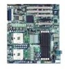
Intel Server Board SE7320SP2 / SE7525GP2 Layout Intel Server Board SE7320SP2 / SE7525GP2 User Guide 18 AB CD E G F MM LL KK JJ II H I : Auxiliary Power Connector CC: Front Panel Connector J: System Fan Header 1 DD: SATA Backplane ... BIOS Select Jumper D: x4 PCI-Express Slot 4, X: Floppy Drive Connector E: PCI Slot 5, 32-bit / 33 MHz Y: SATA A1, A2 Connectors F: x16 PCI-Express Slot 6; SE7320SP2 LX server board only O: Processor 1 Fan Header II: Battery P: Processor Socket 2 JJ: Jumper Block Q: System Fan Header 6 KK: Chassis Intrusion Header R: System Fan Header 5 LL...
Intel Server Board SE7320SP2 / SE7525GP2 Layout Intel Server Board SE7320SP2 / SE7525GP2 User Guide 18 AB CD E G F MM LL KK JJ II H I : Auxiliary Power Connector CC: Front Panel Connector J: System Fan Header 1 DD: SATA Backplane ... BIOS Select Jumper D: x4 PCI-Express Slot 4, X: Floppy Drive Connector E: PCI Slot 5, 32-bit / 33 MHz Y: SATA A1, A2 Connectors F: x16 PCI-Express Slot 6; SE7320SP2 LX server board only O: Processor 1 Fan Header II: Battery P: Processor Socket 2 JJ: Jumper Block Q: System Fan Header 6 KK: Chassis Intrusion Header R: System Fan Header 5 LL...

User Guide
Page 20
Mouse D. Video G. NIC 1 (1Gbit) Figure 4. NIC LEDs NIC NIC1 / NIC2 (Gigabit) LED Color Left LED Right LED LED State Off Solid Amber Blinking Amber Off Solid Amber Solid Green Description No network connection Network ... of each NIC provide the following information. NIC 2 (1Gbit. Back Panel Connectors The NIC LEDs at the right and left LED is on or blinking) 100 Mbps connection 1000 Mbps connection Intel Server Board SE7320SP2 / SE7525GP2 User Guide 20 Table 5. USB 2 C. SE7320SP2 LX server board only) H. Serial port A F. Back Panel Connectors C E A GH...
Mouse D. Video G. NIC 1 (1Gbit) Figure 4. NIC LEDs NIC NIC1 / NIC2 (Gigabit) LED Color Left LED Right LED LED State Off Solid Amber Blinking Amber Off Solid Amber Solid Green Description No network connection Network ... of each NIC provide the following information. NIC 2 (1Gbit. Back Panel Connectors The NIC LEDs at the right and left LED is on or blinking) 100 Mbps connection 1000 Mbps connection Intel Server Board SE7320SP2 / SE7525GP2 User Guide 20 Table 5. USB 2 C. SE7320SP2 LX server board only) H. Serial port A F. Back Panel Connectors C E A GH...

User Guide
Page 21
...make depend on the chassis you are installing the board into the Server Chassis SC5275-E, install the hard drive cage before making your Server Board SE7320SP2 / SE7525GP2 into and the components you are installing. Server Board Features Making Connections to the Server Board The connections you make all of ...the front system fans. Front Panel USB Header G. SATA Connectors I CPU 1 Socket G A. You may not need to the Server Board Intel Server Board SE7320SP2 / SE7525GP2 User Guide 21 SCSI LED Connector K. Floppy Drive Connector C.
...make depend on the chassis you are installing the board into the Server Chassis SC5275-E, install the hard drive cage before making your Server Board SE7320SP2 / SE7525GP2 into and the components you are installing. Server Board Features Making Connections to the Server Board The connections you make all of ...the front system fans. Front Panel USB Header G. SATA Connectors I CPU 1 Socket G A. You may not need to the Server Board Intel Server Board SE7320SP2 / SE7525GP2 User Guide 21 SCSI LED Connector K. Floppy Drive Connector C.

User Guide
Page 38
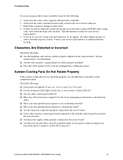
... devices before disconnecting cables: Before disconnecting any external peripheral devices. Make sure your video display monitor). 4. If the power LED does not light, see the documentation supplied with your video display monitor and keyboard are correctly connected to turn off switch on... or configured? ‰ Are all device drivers properly installed? ‰ Are the configuration settings made in the CD-ROM drive. 5. Intel Server Board SE7320SP2 / SE7525GP2 User Guide 38 ‰ Are all peripheral devices installed correctly? ‰ If the system has a hard disk drive, is...
... devices before disconnecting cables: Before disconnecting any external peripheral devices. Make sure your video display monitor). 4. If the power LED does not light, see the documentation supplied with your video display monitor and keyboard are correctly connected to turn off switch on... or configured? ‰ Are all device drivers properly installed? ‰ Are the configuration settings made in the CD-ROM drive. 5. Intel Server Board SE7320SP2 / SE7525GP2 User Guide 38 ‰ Are all peripheral devices installed correctly? ‰ If the system has a hard disk drive, is...

User Guide
Page 39
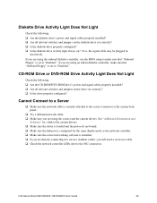
...on button? ‰ Is the system operating normally? If not, see "Diskette Drive Activity Light Does Not Light." ‰ If system LEDs are problems with application software. ƒ The bootable CD-ROM is checked, its activity light should turn on briefly? The prompt varies ...according to 110V or 235V, depending on your service representative or authorized dealer for help. Intel Server Board SE7320SP2 / SE7525GP2 User Guide 39 Check for the following : ‰ Did you cannot correct the problem, contact your power output? ‰...
...on button? ‰ Is the system operating normally? If not, see "Diskette Drive Activity Light Does Not Light." ‰ If system LEDs are problems with application software. ƒ The bootable CD-ROM is checked, its activity light should turn on briefly? The prompt varies ...according to 110V or 235V, depending on your service representative or authorized dealer for help. Intel Server Board SE7320SP2 / SE7525GP2 User Guide 39 Check for the following : ‰ Did you cannot correct the problem, contact your power output? ‰...
User Guide
Page 41
... no characters on light lit? This information is useful for your system has LED lights for changes to the server board? ‰ Are there any of these LEDs lit? ‰ Are any other control panel LEDs lit? ‰ Have any shorted wires caused by pinched-cables or have ...using an add-in the server board connector. 3. If not, see "Power Light Does Not Light" ‰ If your service representative. 5. Intel Server Board SE7320SP2 / SE7525GP2 User Guide 41 Verify that the video controller board is one or more of the fan motors stopped? See the manufacturer's documentation. ...
... no characters on light lit? This information is useful for your system has LED lights for changes to the server board? ‰ Are there any of these LEDs lit? ‰ Are any other control panel LEDs lit? ‰ Have any shorted wires caused by pinched-cables or have ...using an add-in the server board connector. 3. If not, see "Power Light Does Not Light" ‰ If your service representative. 5. Intel Server Board SE7320SP2 / SE7525GP2 User Guide 41 Verify that the video controller board is one or more of the fan motors stopped? See the manufacturer's documentation. ...
User Guide
Page 42
... is securely attached to the NIC connectors. Cannot Connect to a Server ‰ Make sure the network cable is set to "Enabled." Intel Server Board SE7320SP2 / SE7525GP2 User Guide 42 If you are using the onboard diskette controller, use the BIOS setup to make sure that "Onboard Floppy"... is installed. ‰ If you are directly connecting two servers (without a hub), you will need a crossover cable. ‰ Check the network controller LEDs...
... is securely attached to the NIC connectors. Cannot Connect to a Server ‰ Make sure the network cable is set to "Enabled." Intel Server Board SE7320SP2 / SE7525GP2 User Guide 42 If you are using the onboard diskette controller, use the BIOS setup to make sure that "Onboard Floppy"... is installed. ‰ If you are directly connecting two servers (without a hub), you will need a crossover cable. ‰ Check the network controller LEDs...

User Guide
Page 46
... failure Identify 5v standby power on or S0) ƒ Slow Blink = Low power state (S1 - LED Name ID System fault Function Aid in troubleshooting your system. No action required. LED Information The Intel® Server Board SE7320SP2 / SE7525GP2 includes LEDs that can aid in server identification from the back panel Visible fault warning Location Control...
... failure Identify 5v standby power on or S0) ƒ Slow Blink = Low power state (S1 - LED Name ID System fault Function Aid in troubleshooting your system. No action required. LED Information The Intel® Server Board SE7320SP2 / SE7525GP2 includes LEDs that can aid in server identification from the back panel Visible fault warning Location Control...


