User Guide
Page 13
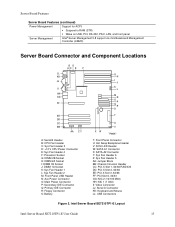
...Server Management Intel® Server Management 5.8 support via mini Baseboard Management Controller (mBMC) Server Board Connector and Component Locations BD AC E F ILIL HKHK GJJG FIIF EHEH DGDG CFFC EE DD CC BB AA Z Y A: Serial B Header B: CPU Fan Header C: Sys Fan Header 3 D: +12 V CPU Power Connector E: Sys Fan Header 4 F: Processor Socket G: DIMM 2B Socket H: DIMM 2A Socket I: DIMM 1B Socket... NIC 1 (1 Gbit) II: Video Connector JJ: Serial A Connector KK: Keyboard and Mouse LL: USB Connectors Figure 2. Intel Server Board SE7210TP1-E Layout Intel Server Board SE7210TP1-E User Guide 13
...Server Management Intel® Server Management 5.8 support via mini Baseboard Management Controller (mBMC) Server Board Connector and Component Locations BD AC E F ILIL HKHK GJJG FIIF EHEH DGDG CFFC EE DD CC BB AA Z Y A: Serial B Header B: CPU Fan Header C: Sys Fan Header 3 D: +12 V CPU Power Connector E: Sys Fan Header 4 F: Processor Socket G: DIMM 2B Socket H: DIMM 2A Socket I: DIMM 1B Socket... NIC 1 (1 Gbit) II: Video Connector JJ: Serial A Connector KK: Keyboard and Mouse LL: USB Connectors Figure 2. Intel Server Board SE7210TP1-E Layout Intel Server Board SE7210TP1-E User Guide 13
User Guide
Page 14
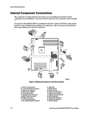
...shown in Figure 3. You may not need to the Server Board A: CPU1 Fan Connector B: +12V CPU Power Connector C: System Fan Header 2 D: System Fan Header 1 E: Front USB Header F: Auxiliary Power Connector G: Main Power Connector H: Floppy Connector I JU K TP00507 Figure 3. If your connections. Server Board Features Internal Component Connections The connections you make ...A1 M: SATA Port A2 N: System Fan Header 6 O: System Fan Header 5 P: Chassis Intrusion Header Q: IDE Connectors R: System Fan Header 4 S: System Fan Header 3 T: Serial B Header 14 Intel Server Board SE7210TP1-E User Guide
...shown in Figure 3. You may not need to the Server Board A: CPU1 Fan Connector B: +12V CPU Power Connector C: System Fan Header 2 D: System Fan Header 1 E: Front USB Header F: Auxiliary Power Connector G: Main Power Connector H: Floppy Connector I JU K TP00507 Figure 3. If your connections. Server Board Features Internal Component Connections The connections you make ...A1 M: SATA Port A2 N: System Fan Header 6 O: System Fan Header 5 P: Chassis Intrusion Header Q: IDE Connectors R: System Fan Header 4 S: System Fan Header 3 T: Serial B Header 14 Intel Server Board SE7210TP1-E User Guide
User Guide
Page 40
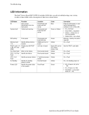
... = Fault On = Fault On = Fault On = 5v standby power on ƒ Off = Power is listed below. Troubleshooting LED Information The Intel® Server Board SE7210TP1-E includes LEDs that can be Off, Green, Amber, Red Amber Amber Amber Amber Green Correction Press ID LED button or user... SE7210TP1-E User Guide LED Name ID System fault Function Aid in troubleshooting your system. A table of these LEDs with a description of board Front center board Front center board 1" behind processor socket Front left board Front Panel Green Amber Each LED can aid in server identification from the back...
... = Fault On = Fault On = Fault On = 5v standby power on ƒ Off = Power is listed below. Troubleshooting LED Information The Intel® Server Board SE7210TP1-E includes LEDs that can be Off, Green, Amber, Red Amber Amber Amber Amber Green Correction Press ID LED button or user... SE7210TP1-E User Guide LED Name ID System fault Function Aid in troubleshooting your system. A table of these LEDs with a description of board Front center board Front center board 1" behind processor socket Front left board Front Panel Green Amber Each LED can aid in server identification from the back...


