
User Guide
Page 2
...Reserved. Disclaimers Disclaimer Information in this document. Intel products are designed and tested to meet the intended thermal requirements of airflow required for a particular purpose, merchantability, or infringement of others. Intel server boards contain a number of high-density VLSI and ...power delivery components that chooses not to use of Intel products including liability or warranties relating to any patent, copyright or other...
...Reserved. Disclaimers Disclaimer Information in this document. Intel products are designed and tested to meet the intended thermal requirements of airflow required for a particular purpose, merchantability, or infringement of others. Intel server boards contain a number of high-density VLSI and ...power delivery components that chooses not to use of Intel products including liability or warranties relating to any patent, copyright or other...
User Guide
Page 3
... a brief overview of this manual, refer to the Technical Product Specification. See "Additional Information and Software" for Intel products, see http://www.support.intel.com/support/motherboards/server/SE7210TP1-E/compat.htm. Chapter 3 provides instructions on the Intel Entry Server Board SE7210TP1-E. For information about the specific BIOS settings and screens is available in the Technical Product Specification. Preface Preface...
... a brief overview of this manual, refer to the Technical Product Specification. See "Additional Information and Software" for Intel products, see http://www.support.intel.com/support/motherboards/server/SE7210TP1-E/compat.htm. Chapter 3 provides instructions on the Intel Entry Server Board SE7210TP1-E. For information about the specific BIOS settings and screens is available in the Technical Product Specification. Preface Preface...
User Guide
Page 4
... you need more information about this product or information about the accessories that can be used with this server board, go to this link to find the information below: http://www.support.intel.com/support/motherboards/server/SE7210TP1-E/index.htm ƒ In-depth technical information about this product, including BIOS settings and chipset information in the...
... you need more information about this product or information about the accessories that can be used with this server board, go to this link to find the information below: http://www.support.intel.com/support/motherboards/server/SE7210TP1-E/index.htm ƒ In-depth technical information about this product, including BIOS settings and chipset information in the...

User Guide
Page 5
... chassis, power supply, and other modules have passed EMC testing using this guide or any components. for use in this server board. Integration of your local regional rules and regulations, the final configuration of it . EMC Testing Before computer integration, make ... electrical conditions may require additional EMC compliance testing. They can be installed in a Class B device. Do not slide board over any unpainted metal surface on your local Intel Representative. See "Error! This is unplugged before opening it into a Class B chassis does not result in offices, ...
... chassis, power supply, and other modules have passed EMC testing using this guide or any components. for use in this server board. Integration of your local regional rules and regulations, the final configuration of it . EMC Testing Before computer integration, make ... electrical conditions may require additional EMC compliance testing. They can be installed in a Class B device. Do not slide board over any unpainted metal surface on your local Intel Representative. See "Error! This is unplugged before opening it into a Class B chassis does not result in offices, ...
User Guide
Page 6
... by that slips over two jumper pins. Resource CD http://www.support.intel.com/support/motherboards/server/SE7210TP1E. 上的 Intel Server Boards and Server Chassis Safety Information(《Intel Consignes de sécurité Lisez attention toutes les consignes de s&#... instruction. vi grip the narrow sides of the instructions. Vea Intel Server Boards and Server Chassis Safety Information en el CD Resource y/o en http://www.support.intel.com/support/motherboards/server/SE7210TP1-E. Wichtige Sicherheitshinweise Lesen Sie zunächst sämtliche Warn-...
... by that slips over two jumper pins. Resource CD http://www.support.intel.com/support/motherboards/server/SE7210TP1E. 上的 Intel Server Boards and Server Chassis Safety Information(《Intel Consignes de sécurité Lisez attention toutes les consignes de s&#... instruction. vi grip the narrow sides of the instructions. Vea Intel Server Boards and Server Chassis Safety Information en el CD Resource y/o en http://www.support.intel.com/support/motherboards/server/SE7210TP1-E. Wichtige Sicherheitshinweise Lesen Sie zunächst sämtliche Warn-...
User Guide
Page 7
... and Component Locations 13 Internal Component Connections 14 Configuration Jumpers ...15 Back Panel Connectors...16 Hardware Requirements ...17 2 Server Board Installations and Upgrades 19 Before You Begin ...19 Tools and Supplies Needed 19 Installing and Removing Memory 19 Installing DIMMs...... or Replacing the Processor 21 Installing the Processor 21 Removing the Processor 24 Installing a PCI Card ...24 Replacing the Backup Battery 24 3 Server Utilities 27 BIOS Setup ...27 Upgrading the BIOS ...28 Preparing for the Upgrade 28 Upgrading the BIOS ...29 Changing the BIOS Language 30...
... and Component Locations 13 Internal Component Connections 14 Configuration Jumpers ...15 Back Panel Connectors...16 Hardware Requirements ...17 2 Server Board Installations and Upgrades 19 Before You Begin ...19 Tools and Supplies Needed 19 Installing and Removing Memory 19 Installing DIMMs...... or Replacing the Processor 21 Installing the Processor 21 Removing the Processor 24 Installing a PCI Card ...24 Replacing the Backup Battery 24 3 Server Utilities 27 BIOS Setup ...27 Upgrading the BIOS ...28 Preparing for the Upgrade 28 Upgrading the BIOS ...29 Changing the BIOS Language 30...
User Guide
Page 9
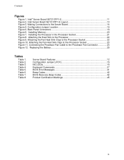
... Figure 1. Connecting the Processor Fan Cable to the Processor Socket 23 Figure 11. Attaching the Fan Heat Sink Clips to the Server Board 14 Figure 4. Making Connections to the Processor Socket 22 Figure 10. Attaching the Heat Sink to the Processor 22 Figure 9. Table 4. Table 2. Intel Server Board SE7210TP1-E Layout 13 Figure 3. Table 5. Table 3. Installing Memory 20 Figure...
... Figure 1. Connecting the Processor Fan Cable to the Processor Socket 23 Figure 11. Attaching the Fan Heat Sink Clips to the Server Board 14 Figure 4. Making Connections to the Processor Socket 22 Figure 10. Attaching the Heat Sink to the Processor 22 Figure 9. Table 4. Table 2. Intel Server Board SE7210TP1-E Layout 13 Figure 3. Table 5. Table 3. Installing Memory 20 Figure...

User Guide
Page 11
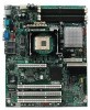
... Serial ATA, and dual-channel Parallel ATA support. The Server Board SE7210TP1-E is provided for Serial ATA drives. ƒ The server board SE7210TP1SCSI includes a single channel, Ultra320 SCSI controller: Adaptec* AIC-7901. Figure 1. Intel® Server Board SE7210TP1-E Intel Server Board SE7210TP1-E User Guide 11 This server board is available in the following picture. Server Board Features 1 Server Board Features This chapter briefly describes the main features of important...
... Serial ATA, and dual-channel Parallel ATA support. The Server Board SE7210TP1-E is provided for Serial ATA drives. ƒ The server board SE7210TP1SCSI includes a single channel, Ultra320 SCSI controller: Adaptec* AIC-7901. Figure 1. Intel® Server Board SE7210TP1-E Intel Server Board SE7210TP1-E User Guide 11 This server board is available in the following picture. Server Board Features 1 Server Board Features This chapter briefly describes the main features of important...
User Guide
Page 12
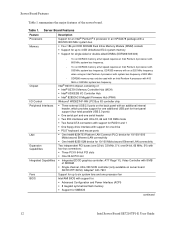
... sockets ƒ Support for up to 4 GB Unbuffered ECC system memory ƒ Support for single-sided or double-sided DIMMs (DDR266/333/400) Chipset I /O controller chip ƒ Three external USB 2.0 ports on server board SE7210TP1SCSI): Adaptec* AIC-7901 Support for an Intel®...second Ethernet LAN connectivity ƒ One Intel® 82551QM device for SMBIOS continued 12 Intel Server Board SE7210TP1-E User Guide To run at full speed requires an Intel Pentium 4 processor with 400 MHz or 533 MHz system bus frequency. Server Board Features Table 1 summarizes the major features...
... sockets ƒ Support for up to 4 GB Unbuffered ECC system memory ƒ Support for single-sided or double-sided DIMMs (DDR266/333/400) Chipset I /O controller chip ƒ Three external USB 2.0 ports on server board SE7210TP1SCSI): Adaptec* AIC-7901 Support for an Intel®...second Ethernet LAN connectivity ƒ One Intel® 82551QM device for SMBIOS continued 12 Intel Server Board SE7210TP1-E User Guide To run at full speed requires an Intel Pentium 4 processor with 400 MHz or 533 MHz system bus frequency. Server Board Features Table 1 summarizes the major features...
User Guide
Page 13
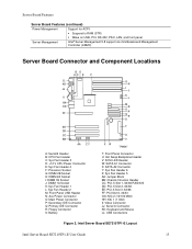
Intel Server Board SE7210TP1-E Layout Intel Server Board SE7210TP1-E User Guide 13 Server Board Features Server Board Features (continued) Power Management Support for ACPI: ƒ Suspend to RAM (STR) ƒ Wake on USB, PCI, RS-232, PS/2, LAN, and front panel Server Management Intel® Server Management 5.8 support via mini Baseboard Management Controller (mBMC) Server Board Connector and Component Locations BD AC E F ILIL HKHK GJJG FIIF EHEH DGDG...
Intel Server Board SE7210TP1-E Layout Intel Server Board SE7210TP1-E User Guide 13 Server Board Features Server Board Features (continued) Power Management Support for ACPI: ƒ Suspend to RAM (STR) ƒ Wake on USB, PCI, RS-232, PS/2, LAN, and front panel Server Management Intel® Server Management 5.8 support via mini Baseboard Management Controller (mBMC) Server Board Connector and Component Locations BD AC E F ILIL HKHK GJJG FIIF EHEH DGDG...
User Guide
Page 14
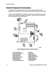
... Port A1 M: SATA Port A2 N: System Fan Header 6 O: System Fan Header 5 P: Chassis Intrusion Header Q: IDE Connectors R: System Fan Header 4 S: System Fan Header 3 T: Serial B Header 14 Intel Server Board SE7210TP1-E User Guide This is necessary because the hard drive cage contains one of the connections shown in Figure 3. You may not need to the...
... Port A1 M: SATA Port A2 N: System Fan Header 6 O: System Fan Header 5 P: Chassis Intrusion Header Q: IDE Connectors R: System Fan Header 4 S: System Fan Header 3 T: Serial B Header 14 Intel Server Board SE7210TP1-E User Guide This is necessary because the hard drive cage contains one of the connections shown in Figure 3. You may not need to the...
User Guide
Page 15
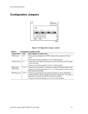
... 13-14 for normal operation. These pins should be jumpered on 5-6 for normal operation. Configuration Jumper [J1D1] Jumper Name Pins What happens at system reset... Server Board Features Configuration Jumpers J1D1 15 14 13 11 10 9 765 3 21 TP00630 Figure 4. Intel Server Board SE7210TP1-E User Guide 15
... 13-14 for normal operation. These pins should be jumpered on 5-6 for normal operation. Configuration Jumper [J1D1] Jumper Name Pins What happens at system reset... Server Board Features Configuration Jumpers J1D1 15 14 13 11 10 9 765 3 21 TP00630 Figure 4. Intel Server Board SE7210TP1-E User Guide 15

User Guide
Page 16
... Mbit) Figure 5. Back Panel Connectors The NIC LEDs at the right and left LED is on or blinking) 100 Mbps connection 1000 Mbps connection 16 Intel Server Board SE7210TP1-E User Guide Table 3. NIC LEDs NIC NIC2 (10/100 Mbit) LED Color Left LED NIC1 (Gigabit) Right LED Left LED Right LED LED State Off...
... Mbit) Figure 5. Back Panel Connectors The NIC LEDs at the right and left LED is on or blinking) 100 Mbps connection 1000 Mbps connection 16 Intel Server Board SE7210TP1-E User Guide Table 3. NIC LEDs NIC NIC2 (10/100 Mbit) LED Color Left LED NIC1 (Gigabit) Right LED Left LED Right LED LED State Off...
User Guide
Page 17
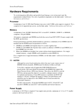
...; DIMM 2A and DIMM 2B: Populate these sockets in socket DIMM 1A. For single- This allows the BIOS to read the SPD data and program the chipset to mix various sizes of 450 Watts is installed, the BIOS will not boot. Intel Server Board SE7210TP1-E User Guide 17 Server Board Features Hardware Requirements To avoid integration difficulties and...
...; DIMM 2A and DIMM 2B: Populate these sockets in socket DIMM 1A. For single- This allows the BIOS to read the SPD data and program the chipset to mix various sizes of 450 Watts is installed, the BIOS will not boot. Intel Server Board SE7210TP1-E User Guide 17 Server Board Features Hardware Requirements To avoid integration difficulties and...
User Guide
Page 19
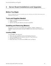
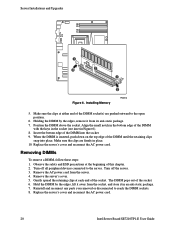
... Information at the beginning of this manual. Installing DIMMs To install DIMMs, follow these steps: 1. Turn off the server. 3. Disconnect the AC power cord. 4. Remove the chassis cover and locate the DIMM sockets (see Figure 6). Intel Server Board SE7210TP1-E User Guide 19 Tools and Supplies Needed ƒ Phillips* (cross head) screwdriver (#1 bit and #2 bit) ƒ Needle...
... Information at the beginning of this manual. Installing DIMMs To install DIMMs, follow these steps: 1. Turn off the server. 3. Disconnect the AC power cord. 4. Remove the chassis cover and locate the DIMM sockets (see Figure 6). Intel Server Board SE7210TP1-E User Guide 19 Tools and Supplies Needed ƒ Phillips* (cross head) screwdriver (#1 bit and #2 bit) ƒ Needle...
User Guide
Page 20
... DIMM into place. Position the DIMM above the socket. Remove the AC power cord from its anti-static package. 7. The DIMM pops out of the socket. Replace the server's cover and reconnect the AC power cord. 20 Intel Server Board SE7210TP1-E User Guide Holding the DIMM by the edges,... lift it away from the socket, and store it from the server. 4. Reinstall and reconnect any parts you removed ...
... DIMM into place. Position the DIMM above the socket. Remove the AC power cord from its anti-static package. 7. The DIMM pops out of the socket. Replace the server's cover and reconnect the AC power cord. 20 Intel Server Board SE7210TP1-E User Guide Holding the DIMM by the edges,... lift it away from the socket, and store it from the server. 4. Reinstall and reconnect any parts you removed ...
User Guide
Page 21
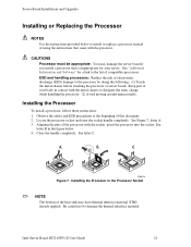
... chassis before touching the processor or server board. Intel Server Board SE7210TP1-E User Guide 21 Keep part of electrostatic discharge (ESD) damage to the list of this document. 2. See Figure 7, letter A. 3. Be careful not to install or replace a processor instead of the processor with the socket, insert the processor into the socket. CAUTIONS Processor must be appropriate: You...
... chassis before touching the processor or server board. Intel Server Board SE7210TP1-E User Guide 21 Keep part of electrostatic discharge (ESD) damage to the list of this document. 2. See Figure 7, letter A. 3. Be careful not to install or replace a processor instead of the processor with the socket, insert the processor into the socket. CAUTIONS Processor must be appropriate: You...
User Guide
Page 22
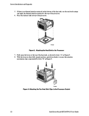
Attaching the Fan Heat Sink Clips to the Processor 7. Attaching the Heat Sink to the Processor Socket 22 Intel Server Board SE7210TP1-E User Guide Fully open the levers at the top of the processor. 6. With the levers in their fully opened position, push down firmly to the ... secure the retention mechanism clips, represented by letter "A" in Figure 9. TP00520 Figure 8. B B B B A A C TP00521 Figure 9. Place the fan heat sink on the bottom of the processor. Server Installations and Upgrades 5.
Attaching the Fan Heat Sink Clips to the Processor 7. Attaching the Heat Sink to the Processor Socket 22 Intel Server Board SE7210TP1-E User Guide Fully open the levers at the top of the processor. 6. With the levers in their fully opened position, push down firmly to the ... secure the retention mechanism clips, represented by letter "A" in Figure 9. TP00520 Figure 8. B B B B A A C TP00521 Figure 9. Place the fan heat sink on the bottom of the processor. Server Installations and Upgrades 5.
User Guide
Page 23
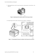
Firmly push the levers closed. TP00522 Figure 10. TP00523 Figure 11. See Figure 11. It may be necessary to exert pressure to the processor fan connector. Connect the processor fan cable to close the levers. See Figure 10. Connecting the Processor Fan Cable to the Processor Socket 10. Attaching the Fan Heat Sink Clips to the Processor Fan Connector Intel Server Board SE7210TP1-E User Guide 23 Server Board Installations and Upgrades 9.
Firmly push the levers closed. TP00522 Figure 10. TP00523 Figure 11. See Figure 11. It may be necessary to exert pressure to the processor fan connector. Connect the processor fan cable to close the levers. See Figure 10. Connecting the Processor Fan Cable to the Processor Socket 10. Attaching the Fan Heat Sink Clips to the Processor Fan Connector Intel Server Board SE7210TP1-E User Guide 23 Server Board Installations and Upgrades 9.

User Guide
Page 24
...3. When the battery starts to remove the shield. Eksplosionsfare ved fejlagtig håndtering. Levér det brugte batteri tilbage til leverandøren. 24 Intel Server Board SE7210TP1-E User Guide Remove the processor. If a low profile card is incorrectly replaced. WARNING Danger of the heat sink. 5. Lift the processor lever. 7.... card or slot. 3. Lithiumbatteri - Contact your system and must be wrong. ADVARSEL! Retain the screw. 2. Open the levers on the server board powers the RTC for up to 10 years in step 1 to secure the PCI card to manufacturer's instructions.
...3. When the battery starts to remove the shield. Eksplosionsfare ved fejlagtig håndtering. Levér det brugte batteri tilbage til leverandøren. 24 Intel Server Board SE7210TP1-E User Guide Remove the processor. If a low profile card is incorrectly replaced. WARNING Danger of the heat sink. 5. Lift the processor lever. 7.... card or slot. 3. Lithiumbatteri - Contact your system and must be wrong. ADVARSEL! Retain the screw. 2. Open the levers on the server board powers the RTC for up to 10 years in step 1 to secure the PCI card to manufacturer's instructions.


