
User Guide
Page 2
... or the server board does not operate correctly when used together. Intel products are not designed, intended or authorized for use Intel developed server building blocks to consult vendor datasheets and operating parameters to meet the intended thermal requirements of their specific application and environmental conditions. All Rights Reserved ii Intel® Server System SC5400RA User's Guide Intel's own chassis...
... or the server board does not operate correctly when used together. Intel products are not designed, intended or authorized for use Intel developed server building blocks to consult vendor datasheets and operating parameters to meet the intended thermal requirements of their specific application and environmental conditions. All Rights Reserved ii Intel® Server System SC5400RA User's Guide Intel's own chassis...
User Guide
Page 3
... Intel Server Boards and Server Chassis Safety Information en el Intel® Server Deployment Toolkit 2.0 CD y/o en http:// support.intel.com/support/motherboards/server/sb/cs-010770.htm. Beachten Sie hierzu auch die Sicherheitshinweise zu Intel-Serverplatinen und Servergehäusen auf der Intel® Server Deployment Toolkit 2.0 CD oder unter http://support.intel.com/support/motherboards/server/sb/cs-010770.htm. Intel® Server System SC5400RA...
... Intel Server Boards and Server Chassis Safety Information en el Intel® Server Deployment Toolkit 2.0 CD y/o en http:// support.intel.com/support/motherboards/server/sb/cs-010770.htm. Beachten Sie hierzu auch die Sicherheitshinweise zu Intel-Serverplatinen und Servergehäusen auf der Intel® Server Deployment Toolkit 2.0 CD oder unter http://support.intel.com/support/motherboards/server/sb/cs-010770.htm. Intel® Server System SC5400RA...
User Guide
Page 8
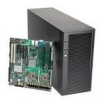
... can be used with the following items: • One Intel® server board SC5400RA, installed in the chassis • One 830-watt power supply, installed in the chassis • One box of hardware components, referred to purchase one or more of system management software: - One Intel® Deployment Assistant CD In addition, you may need or...
... can be used with the following items: • One Intel® server board SC5400RA, installed in the chassis • One 830-watt power supply, installed in the chassis • One box of hardware components, referred to purchase one or more of system management software: - One Intel® Deployment Assistant CD In addition, you may need or...

User Guide
Page 11
...ix Chapter 1: Server System Features 1 Component Identification 4 Front Control Panel 5 Intel® Local Control Panel (optional component 7 Back Panel Features 8 Peripheral Devices 10 Server Board Connector and Header Locations 11 Configuration Jumpers 13 Intel® Light-Guided Diagnostics 15 Intel® Remote ...23 System References 23 Removing and Installing the Chassis Cover 24 Removing the Chassis Cover 24 Installing the Chassis Cover 25 Removing and Installing the Front Bezel 26 Removing the Bezel Assembly (Pedestal Only 26 Intel® Server System SC5400RA User...
...ix Chapter 1: Server System Features 1 Component Identification 4 Front Control Panel 5 Intel® Local Control Panel (optional component 7 Back Panel Features 8 Peripheral Devices 10 Server Board Connector and Header Locations 11 Configuration Jumpers 13 Intel® Light-Guided Diagnostics 15 Intel® Remote ...23 System References 23 Removing and Installing the Chassis Cover 24 Removing the Chassis Cover 24 Installing the Chassis Cover 25 Removing and Installing the Front Bezel 26 Removing the Bezel Assembly (Pedestal Only 26 Intel® Server System SC5400RA User...
User Guide
Page 12
... 83 Replacing a System Fan 84 Installing an Additional Hot-swap Power Supply Module 85 Replacing a Hot-swap Power Supply 86 Replacing the Power Distribution Board 88 Replacing the CMOS Battery 97 Replacing the Server Board 99 Removing the Server Board 99 Installing a Server Board 102 Chapter 3: System Utilities 105 Using the BIOS Setup Utility 105 xii Intel® Server System SC5400RA User's Guide
... 83 Replacing a System Fan 84 Installing an Additional Hot-swap Power Supply Module 85 Replacing a Hot-swap Power Supply 86 Replacing the Power Distribution Board 88 Replacing the CMOS Battery 97 Replacing the Server Board 99 Removing the Server Board 99 Installing a Server Board 102 Chapter 3: System Utilities 105 Using the BIOS Setup Utility 105 xii Intel® Server System SC5400RA User's Guide

User Guide
Page 17
Intel® Server System SC5400RA 1 Figure 2. Server System Back 8 Figure 6. Optional Peripherals 10 Figure 8. Server Board Connector and Component Locations 12 Figure 9. DIMM Sockets...20 Figure 12. Removing the Chassis ...Drive Cage 34 Figure 27. Removing Drive Carrier from Hot-swap Cage 40 Figure 38. List of Figures Figure 1. System LEDs ...16 Figure 11. Installing the Chassis Cover 25 Figure 14. Removing Six-drive Fixed Drive Cage 28 Figure 17.... Tightening Thumb Screw 37 Figure 33. Removing Cage Top from Drive Cage 43 Intel® Server System SC5400RA User's Guide xvii
Intel® Server System SC5400RA 1 Figure 2. Server System Back 8 Figure 6. Optional Peripherals 10 Figure 8. Server Board Connector and Component Locations 12 Figure 9. DIMM Sockets...20 Figure 12. Removing the Chassis ...Drive Cage 34 Figure 27. Removing Drive Carrier from Hot-swap Cage 40 Figure 38. List of Figures Figure 1. System LEDs ...16 Figure 11. Installing the Chassis Cover 25 Figure 14. Removing Six-drive Fixed Drive Cage 28 Figure 17.... Tightening Thumb Screw 37 Figure 33. Removing Cage Top from Drive Cage 43 Intel® Server System SC5400RA User's Guide xvii

User Guide
Page 24
...of 64 MB memory • Quad-channel memory architecture • Intel® 6321ESB I/O Controller Hub • Intel® 5000P Memory Controller Hub 2 Intel® Server System SC5400RA User's Guide Upgradable to 830-W redundant power by the Intel® RAID Activation Key AXXRAKSW5. • Front Control Panel • Intel® Local... USB ports • One internal USB port on the server board • On-board ATI* ES1000 video controller with 16-MB DDR SDRAM • One rear panel video port Support for up to two Quad-Core Intel® Xeon® processors with a 677-, 1066-, ...
...of 64 MB memory • Quad-channel memory architecture • Intel® 6321ESB I/O Controller Hub • Intel® 5000P Memory Controller Hub 2 Intel® Server System SC5400RA User's Guide Upgradable to 830-W redundant power by the Intel® RAID Activation Key AXXRAKSW5. • Front Control Panel • Intel® Local... USB ports • One internal USB port on the server board • On-board ATI* ES1000 video controller with 16-MB DDR SDRAM • One rear panel video port Support for up to two Quad-Core Intel® Xeon® processors with a 677-, 1066-, ...

User Guide
Page 34
... (see Figure 6 on page 15) M. Diagnostic and Identify LEDs (see "Intel® Light-Guided Diagnostics" on page 15) N. Intel® Local Control Panel header LL. Chassis intrusion header Figure 8. Server Board Connector and Component Locations 12 Intel® Server System SC5400RA User's Guide RMM connector (connector for Intel® Remote Management Module) K. USB header Z. Main power connector X. SATA_Key: SATA...
... (see Figure 6 on page 15) M. Diagnostic and Identify LEDs (see "Intel® Light-Guided Diagnostics" on page 15) N. Intel® Local Control Panel header LL. Chassis intrusion header Figure 8. Server Board Connector and Component Locations 12 Intel® Server System SC5400RA User's Guide RMM connector (connector for Intel® Remote Management Module) K. USB header Z. Main power connector X. SATA_Key: SATA...

User Guide
Page 37
...LED AF001420 Function POST LED. The sequence of lit POST LEDs is used to help you identify the server from among several servers. Intel® Light-Guided Diagnostics The server board contains diagnostic LEDs to help you identify failed and failing components and to identify specific errors that might... these LEDs. The sequence of lit POST LEDs is used to identify specific errors that might occur during the boot process. Intel® Server System SC5400RA User's Guide 15 B C A D E F J K A1 C1 A2 C2 A3 C3 A4 C4 B1 D1 G B2 D2 B3 D3 H...
...LED AF001420 Function POST LED. The sequence of lit POST LEDs is used to help you identify the server from among several servers. Intel® Light-Guided Diagnostics The server board contains diagnostic LEDs to help you identify failed and failing components and to identify specific errors that might... these LEDs. The sequence of lit POST LEDs is used to identify specific errors that might occur during the boot process. Intel® Server System SC5400RA User's Guide 15 B C A D E F J K A1 C1 A2 C2 A3 C3 A4 C4 B1 D1 G B2 D2 B3 D3 H...

User Guide
Page 39
...Installation Options Your Intel® Server System SC5400RA can insert a CD-ROM disk in the second position from the bottom of the server board, not as its own CD-ROM drive. When installing the server system into a rack, Intel recommends you to view and operate the server remotely, in ...-less rail kit, ARIGRACK) Storage Device Options The Intel® Server System SC5400RA supports the following drive options: • Optical hard disk drives • Six SATA ports at 3 GB/s • Parallel ATA (IDE): The server board includes one IDE connector. This provides remote control. ...
...Installation Options Your Intel® Server System SC5400RA can insert a CD-ROM disk in the second position from the bottom of the server board, not as its own CD-ROM drive. When installing the server system into a rack, Intel recommends you to view and operate the server remotely, in ...-less rail kit, ARIGRACK) Storage Device Options The Intel® Server System SC5400RA supports the following drive options: • Optical hard disk drives • Six SATA ports at 3 GB/s • Parallel ATA (IDE): The server board includes one IDE connector. This provides remote control. ...
User Guide
Page 41
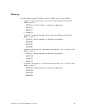
...DIMM_A4 • Channel B is in the right riser card, nearest to the right side of the server board. This channel consists of - DIMM_C2 - Memory The Intel® Server System SC5400RA provides 16 DIMM sockets in four channels: • Channel A is in the right riser card, nearest... to the right side of the server board. DIMM_B1 (must be populated for minimum configuration) - DIMM_D1 (must be populated ...
...DIMM_A4 • Channel B is in the right riser card, nearest to the right side of the server board. This channel consists of - DIMM_C2 - Memory The Intel® Server System SC5400RA provides 16 DIMM sockets in four channels: • Channel A is in the right riser card, nearest... to the right side of the server board. DIMM_B1 (must be populated for minimum configuration) - DIMM_D1 (must be populated ...
User Guide
Page 44
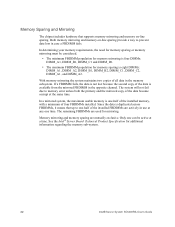
...system, the maximum usable memory is eight DIMMs: DIMM_A1, DIMM_A2, DIMM_B1, DIMM_B2, DIMM_C1, DIMM_C2, DIMM_A1, and DIMM_A2. Memory mirroring and memory sparing are used for memory sparing is one-half of the installed memory, with a minimum of the data become corrupt at a time. See the Intel® Server Board... FBDIMM fails. In determining your memory requirements, the need for additional information regarding the memory sub-system. 22 Intel® Server System SC5400RA User's Guide The system will not fail due to memory error unless both the primary and the mirrored copy of four ...
...system, the maximum usable memory is eight DIMMs: DIMM_A1, DIMM_A2, DIMM_B1, DIMM_B2, DIMM_C1, DIMM_C2, DIMM_A1, and DIMM_A2. Memory mirroring and memory sparing are used for memory sparing is one-half of the installed memory, with a minimum of the data become corrupt at a time. See the Intel® Server Board... FBDIMM fails. In determining your memory requirements, the need for additional information regarding the memory sub-system. 22 Intel® Server System SC5400RA User's Guide The system will not fail due to memory error unless both the primary and the mirrored copy of four ...
User Guide
Page 70
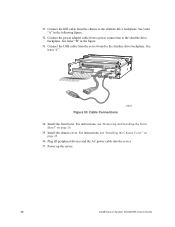
... AC power cable into the server. 37. Power up the server. 48 Intel® Server System SC5400RA User's Guide Install the front bezel. For instructions, see "Removing and Installing the Front Bezel" on page 25. 36. Install the chassis cover. A B C Figure 53. Cable Connections AF000491 34. Connect the IDE cable from the server board to the slimline drive...
... AC power cable into the server. 37. Power up the server. 48 Intel® Server System SC5400RA User's Guide Install the front bezel. For instructions, see "Removing and Installing the Front Bezel" on page 25. 36. Install the chassis cover. A B C Figure 53. Cable Connections AF000491 34. Connect the IDE cable from the server board to the slimline drive...
User Guide
Page 76
... following figure. 7. Turn off the server. 3. Install the chassis cover. Add-in boards that draw excessive current. Turn off all peripheral devices and the AC power cable into the server. 12. Remove the chassis cover. Install the front bezel. See letter "A" in cards. See letter "C". 54 Intel® Server System SC5400RA User's Guide For instructions, see "Removing...
... following figure. 7. Turn off the server. 3. Install the chassis cover. Add-in boards that draw excessive current. Turn off all peripheral devices and the AC power cable into the server. 12. Remove the chassis cover. Install the front bezel. See letter "A" in cards. See letter "C". 54 Intel® Server System SC5400RA User's Guide For instructions, see "Removing...
User Guide
Page 78
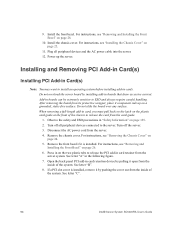
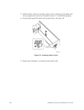
Hold the add-in the following figure. 12. See letter "A" in card by its top edge or upper corners. Installing Add-in cards. 56 Intel® Server System SC5400RA User's Guide See letter "B". A B AF000599 Figure 61. Repeat steps 6 through 12 to install any other add-in Card 13. Close the back panel PCI add-in card into an expansion slot on the server board. Firmly press the add-in card retention device. 11.
Hold the add-in the following figure. 12. See letter "A" in card by its top edge or upper corners. Installing Add-in cards. 56 Intel® Server System SC5400RA User's Guide See letter "B". A B AF000599 Figure 61. Repeat steps 6 through 12 to install any other add-in Card 13. Close the back panel PCI add-in card into an expansion slot on the server board. Firmly press the add-in card retention device. 11.
User Guide
Page 81
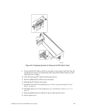
...corners and lift it from the expansion slot on the server board. Plug all peripheral devices and the AC power cable into the server. 16. Remove additional PCI add-in Card 9. For instructions, see "Installing the Chassis Cover" on page 26. 14. Preparing System for Removal of PCI Add-in card as necessary.... and Installing the Front Bezel" on page 25. 15. Close the back panel PCI add-in an antistatic protective wrapper. 10. Power up the server. Install the chassis cover. Intel® Server System SC5400RA User's Guide 59 A A B AF000600 Figure 63. Place the removed PCI add-in...
...corners and lift it from the expansion slot on the server board. Plug all peripheral devices and the AC power cable into the server. 16. Remove additional PCI add-in Card 9. For instructions, see "Installing the Chassis Cover" on page 26. 14. Preparing System for Removal of PCI Add-in card as necessary.... and Installing the Front Bezel" on page 25. 15. Close the back panel PCI add-in an antistatic protective wrapper. 10. Power up the server. Install the chassis cover. Intel® Server System SC5400RA User's Guide 59 A A B AF000600 Figure 63. Place the removed PCI add-in...
User Guide
Page 82
The server board includes two memory riser cards that are sensitive to the server. Disconnect the AC power cord from the system, place it with the component side facing up on page 129. 2. Loosen the thumbscrew on riser card 1; See letter "B"...on page ix for this installation. Observe the safety and ESD precautions in the figure. 60 Intel® Server System SC5400RA User's Guide Turn off the server. 3. After removing a memory riser card from the server. 4. DIMM numbering starts from the inside of the memory requirements and options. See "Additional ...
The server board includes two memory riser cards that are sensitive to the server. Disconnect the AC power cord from the system, place it with the component side facing up on page 129. 2. Loosen the thumbscrew on riser card 1; See letter "B"...on page ix for this installation. Observe the safety and ESD precautions in the figure. 60 Intel® Server System SC5400RA User's Guide Turn off the server. 3. After removing a memory riser card from the server. 4. DIMM numbering starts from the inside of the memory requirements and options. See "Additional ...

User Guide
Page 87
Intel® Server System SC5400RA User's Guide 65 Figure 68. Reconnect the AC power cord. 15. Close the door on the server board. 17. Be sure to insert each side edge of the memory riser cards to seat them into the memory cage. Push firmly on the top ...
Intel® Server System SC5400RA User's Guide 65 Figure 68. Reconnect the AC power cord. 15. Close the door on the server board. 17. Be sure to insert each side edge of the memory riser cards to seat them into the memory cage. Push firmly on the top ...

User Guide
Page 89
..." on the cage. 11. Store the FBDIMM in sockets DIMM_C1 and DIMM_D1 on the server board. 10. Replace the chassis cover. Reconnect the AC power cord. Insert the memory board into the socket on memory riser card 2. 9. Intel® Server System SC5400RA User's Guide 67 Close the door on the memory cage and tighten the thumbscrew on...
..." on the cage. 11. Store the FBDIMM in sockets DIMM_C1 and DIMM_D1 on the server board. 10. Replace the chassis cover. Reconnect the AC power cord. Insert the memory board into the socket on memory riser card 2. 9. Intel® Server System SC5400RA User's Guide 67 Close the door on the memory cage and tighten the thumbscrew on...

User Guide
Page 92
... for a link to the processor by doing the following: (1) Touch the metal chassis before touching the processor or server board. Observe the safety and ESD precautions in contact with the metal chassis to the server. Remove the chassis cover. For instructions, see "Removing the Chassis Cover" on either the processor or the processor...) damage to the list of compatible processor(s). See "Additional Information and Software" on page ix for your body in "Safety Information" on page 68. 70 Intel® Server System SC5400RA User's Guide
... for a link to the processor by doing the following: (1) Touch the metal chassis before touching the processor or server board. Observe the safety and ESD precautions in contact with the metal chassis to the server. Remove the chassis cover. For instructions, see "Removing the Chassis Cover" on either the processor or the processor...) damage to the list of compatible processor(s). See "Additional Information and Software" on page ix for your body in "Safety Information" on page 68. 70 Intel® Server System SC5400RA User's Guide

