
User Guide
Page 5
... fingertips or with a pair of the jumper with the function controlled by that jumper. Intel® Server System SC5400RA User's Guide v Take care to grip with, but not squeeze, the pliers or other tool you use to remove or install a jumper; Installing or removing jumpers: A jumper is a small plastic encased conductor that you can damage the contacts inside the jumper, causing intermittent problems with the pliers, never the wide sides...
... fingertips or with a pair of the jumper with the function controlled by that jumper. Intel® Server System SC5400RA User's Guide v Take care to grip with, but not squeeze, the pliers or other tool you use to remove or install a jumper; Installing or removing jumpers: A jumper is a small plastic encased conductor that you can damage the contacts inside the jumper, causing intermittent problems with the pliers, never the wide sides...
User Guide
Page 7
... about the specific BIOS settings and screens is written for system technicians who are responsible for purchasing and using the utilities that are shipped with the board or that may need, troubleshooting information, and instructions on how to add and replace components on page ix for installing or replacing components such as the fans, power supply, drives, and other components you for troubleshooting, upgrading, and repairing this manual, see http:// support.intel.com/support/motherboards/server/SC5400RA/. Preface About...
... about the specific BIOS settings and screens is written for system technicians who are responsible for purchasing and using the utilities that are shipped with the board or that may need, troubleshooting information, and instructions on how to add and replace components on page ix for installing or replacing components such as the fans, power supply, drives, and other components you for troubleshooting, upgrading, and repairing this manual, see http:// support.intel.com/support/motherboards/server/SC5400RA/. Preface About...
User Guide
Page 8
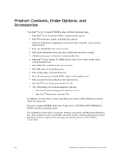
... list as the "server system hardware box" • Fans, pre-installed in your server system • One chassis intrusion switch and cable, installed in your server: Processor, memory DIMMs, hard drive, floppy drive, CD-ROM or DVD-ROM drive, RAID controller, operating system. One Intel® System Management Software 1.5 CD - For information about which accessories, memory, processors, and third-party hardware have been tested and can be used with the following items: • One Intel® server board SC5400RA, installed in the chassis • One 830-watt power supply, installed...
... list as the "server system hardware box" • Fans, pre-installed in your server system • One chassis intrusion switch and cable, installed in your server: Processor, memory DIMMs, hard drive, floppy drive, CD-ROM or DVD-ROM drive, RAID controller, operating system. One Intel® System Management Software 1.5 CD - For information about which accessories, memory, processors, and third-party hardware have been tested and can be used with the following items: • One Intel® server board SC5400RA, installed in the chassis • One 830-watt power supply, installed...

User Guide
Page 11
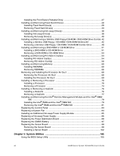
...Panel Features 8 Peripheral Devices 10 Server Board Connector and Header Locations 11 Configuration Jumpers 13 Intel® Light-Guided Diagnostics 15 Intel® Remote Management Module and RMM NIC Accessory 17 Rack-mount Installation Options 17 Storage Device Options 17 Hard Disk Drives ...18 Floppy / CD-ROM / DVD-ROM Slimline Carriers 18 Processor and Memory Requirements 18 Processor ...18 Memory ...19 Chapter 2: Hardware Installations and Upgrades 23 Before You Begin ...23 Tools and Supplies Needed 23 System References 23 Removing and Installing the Chassis Cover 24 Removing...
...Panel Features 8 Peripheral Devices 10 Server Board Connector and Header Locations 11 Configuration Jumpers 13 Intel® Light-Guided Diagnostics 15 Intel® Remote Management Module and RMM NIC Accessory 17 Rack-mount Installation Options 17 Storage Device Options 17 Hard Disk Drives ...18 Floppy / CD-ROM / DVD-ROM Slimline Carriers 18 Processor and Memory Requirements 18 Processor ...18 Memory ...19 Chapter 2: Hardware Installations and Upgrades 23 Before You Begin ...23 Tools and Supplies Needed 23 System References 23 Removing and Installing the Chassis Cover 24 Removing...
User Guide
Page 12
... Intel® RMM NIC ...79 Installing the Intel® RMM and the Intel® RMM NIC 79 Removing the Intel® RMM and the Intel® RMM NIC 81 Replacing the Control Panel 83 Replacing a System Fan 84 Installing an Additional Hot-swap Power Supply Module 85 Replacing a Hot-swap Power Supply 86 Replacing the Power Distribution Board 88 Replacing the CMOS Battery 97 Replacing the Server Board 99 Removing the Server Board 99 Installing a Server Board 102 Chapter 3: System Utilities 105 Using the BIOS Setup Utility 105 xii Intel® Server System SC5400RA User's Guide
... Intel® RMM NIC ...79 Installing the Intel® RMM and the Intel® RMM NIC 79 Removing the Intel® RMM and the Intel® RMM NIC 81 Replacing the Control Panel 83 Replacing a System Fan 84 Installing an Additional Hot-swap Power Supply Module 85 Replacing a Hot-swap Power Supply 86 Replacing the Power Distribution Board 88 Replacing the CMOS Battery 97 Replacing the Server Board 99 Removing the Server Board 99 Installing a Server Board 102 Chapter 3: System Utilities 105 Using the BIOS Setup Utility 105 xii Intel® Server System SC5400RA User's Guide
User Guide
Page 13
... Cannot Access Setup 105 Setup Menus ...106 Upgrading the BIOS 107 Preparing for the Upgrade 108 Upgrading the BIOS 108 Reverting to the Previous BIOS 109 Clearing the Password 110 Clearing the CMOS 112 Chapter 4: Technical Reference 113 Power Cable Routing to Fixed Drives 113 Data Cable Routing to Fixed Drives 114 Power Supply Specifications 115 830-W Single Power Input Voltages 115 830-W Single Power Supply Output Voltages 115 System Environmental Specifications 116 Appendix A: Installation/Assembly Safety Instructions 117...
... Cannot Access Setup 105 Setup Menus ...106 Upgrading the BIOS 107 Preparing for the Upgrade 108 Upgrading the BIOS 108 Reverting to the Previous BIOS 109 Clearing the Password 110 Clearing the CMOS 112 Chapter 4: Technical Reference 113 Power Cable Routing to Fixed Drives 113 Data Cable Routing to Fixed Drives 114 Power Supply Specifications 115 830-W Single Power Input Voltages 115 830-W Single Power Supply Output Voltages 115 System Environmental Specifications 116 Appendix A: Installation/Assembly Safety Instructions 117...

User Guide
Page 24
...-port SATA with BIOS-enabled embedded RAID 0, 1, and 10 with a 1066-, or 1333MHz front side bus • DDR2-533 and DDR2-667 FBDIMM sockets that is standard. The table below summarizes the features of 64 MB memory • Quad-channel memory architecture • Intel® 6321ESB I/O Controller Hub • Intel® 5000P Memory Controller Hub 2 Intel® Server System SC5400RA User's Guide Server System Features Feature Dimensions Hard Drives Peripherals RAID support Control Panel (dependent on option selected) LEDs...
...-port SATA with BIOS-enabled embedded RAID 0, 1, and 10 with a 1066-, or 1333MHz front side bus • DDR2-533 and DDR2-667 FBDIMM sockets that is standard. The table below summarizes the features of 64 MB memory • Quad-channel memory architecture • Intel® 6321ESB I/O Controller Hub • Intel® 5000P Memory Controller Hub 2 Intel® Server System SC5400RA User's Guide Server System Features Feature Dimensions Hard Drives Peripherals RAID support Control Panel (dependent on option selected) LEDs...

User Guide
Page 25
...USB 2.0 ports • One internal USB port that supports a peripheral, such as a floppy drive • One DH10 serial port B header • One ATA-100 40-pin connector • One SSI-compliant 24-pin front control panel header • Support for the Intel® Local Control Panel (optional component sold separately) • Support for the Intel® Remote Management Module (optional component sold separately) • Support for Intel® System Management software • Intel® Light-Guided Diagnostics on field replaceable units Intel® Server System SC5400RA User's Guide...
...USB 2.0 ports • One internal USB port that supports a peripheral, such as a floppy drive • One DH10 serial port B header • One ATA-100 40-pin connector • One SSI-compliant 24-pin front control panel header • Support for the Intel® Local Control Panel (optional component sold separately) • Support for the Intel® Remote Management Module (optional component sold separately) • Support for Intel® System Management software • Intel® Light-Guided Diagnostics on field replaceable units Intel® Server System SC5400RA User's Guide...

User Guide
Page 35
... Password Clear Protect Clear 2 3 J1D2 BMC Force Update Disable Enable 2 3 J1E3 AF001419 Jumper Name BIOS Bank Select (J1C3) CMOS Clear (J1D1) Pins 1 - 2 2 - 3 1 - 2 2 - 3 What Happens at System Reset Bank 0: Boot to pins 1 - 2. Erase CMOS: If these pins should not be jumpered for normal operation. Place the jumper on the next server reset. Protect CMOS: these pins are jumpered for 5 to 10 seconds, the CMOS settings will be jumpered for normal operation. These pins should be jumpered for 5 to 10 seconds. Intel® Server System SC5400RA User's Guide 13 Power...
... Password Clear Protect Clear 2 3 J1D2 BMC Force Update Disable Enable 2 3 J1E3 AF001419 Jumper Name BIOS Bank Select (J1C3) CMOS Clear (J1D1) Pins 1 - 2 2 - 3 1 - 2 2 - 3 What Happens at System Reset Bank 0: Boot to pins 1 - 2. Erase CMOS: If these pins should not be jumpered for normal operation. Place the jumper on the next server reset. Protect CMOS: these pins are jumpered for 5 to 10 seconds, the CMOS settings will be jumpered for normal operation. These pins should be jumpered for 5 to 10 seconds. Intel® Server System SC5400RA User's Guide 13 Power...

User Guide
Page 39
...) Storage Device Options The Intel® Server System SC5400RA supports the following drive options: • Optical hard disk drives • Six SATA ports at 3 GB/s • Parallel ATA (IDE): The server board includes one IDE connector. This provides remote control. USB media redirection allows you to a managing system. When installing the server system into a rack. The order numbers are included in the second position from the bottom of the rack, the second system in the rail kit. Keyboard, video, and mouse control (KVM...
...) Storage Device Options The Intel® Server System SC5400RA supports the following drive options: • Optical hard disk drives • Six SATA ports at 3 GB/s • Parallel ATA (IDE): The server board includes one IDE connector. This provides remote control. USB media redirection allows you to a managing system. When installing the server system into a rack. The order numbers are included in the second position from the bottom of the rack, the second system in the rail kit. Keyboard, video, and mouse control (KVM...
User Guide
Page 40
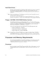
... and Software" on page ix. For instructions on installing hard drives, see "Installing and Removing a Slimline USB Floppy/CD-ROM / DVD-ROM Drive Combo" on page 38. Hard Disk Drives One drive cage that supports six cabled drives ships with the server system. The Intel® Server System SC5400RA does not support all slimline floppy, CD-ROM or DVD-ROM hard drives. To use one of supported hardware. For a list of supported processors, see "Installing and Removing a DVD-ROM or CD-ROM Drive" on page ix. 18 Intel® Server System SC5400RA User's Guide For a list of...
... and Software" on page ix. For instructions on installing hard drives, see "Installing and Removing a Slimline USB Floppy/CD-ROM / DVD-ROM Drive Combo" on page 38. Hard Disk Drives One drive cage that supports six cabled drives ships with the server system. The Intel® Server System SC5400RA does not support all slimline floppy, CD-ROM or DVD-ROM hard drives. To use one of supported hardware. For a list of supported processors, see "Installing and Removing a DVD-ROM or CD-ROM Drive" on page ix. 18 Intel® Server System SC5400RA User's Guide For a list of...
User Guide
Page 76
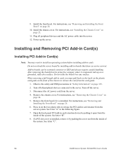
... the inside of the system. Open the back panel PCI add-in card retention device by installing add-in boards that draw excessive current. If a PCI slot cover is installed. For instructions, see "Removing and Installing the Front Bezel" on a grounded, static-free surface. Remove the chassis cover. For instructions, see "Removing and Installing the Front Bezel" on page 129. 2. For instructions, see "Removing the Chassis Cover" on page 25. 11. See letter "B". 8. See letter "C". 54 Intel® Server System SC5400RA User's Guide Power...
... the inside of the system. Open the back panel PCI add-in card retention device by installing add-in boards that draw excessive current. If a PCI slot cover is installed. For instructions, see "Removing and Installing the Front Bezel" on a grounded, static-free surface. Remove the chassis cover. For instructions, see "Removing and Installing the Front Bezel" on page 129. 2. For instructions, see "Removing the Chassis Cover" on page 25. 11. See letter "B". 8. See letter "C". 54 Intel® Server System SC5400RA User's Guide Power...

User Guide
Page 80
... "B". 58 Intel® Server System SC5400RA User's Guide Observe the safety and ESD precautions in "Safety Information" on the two plastic tabs to the server. Turn off all peripheral devices connected to release the PCI add-in card retainer from the card guide. 1. Open the back panel PCI add-in card retention device by pulling it is installed. Turn off the server. 3. For instructions, see "Removing and Installing the Front Bezel" on page 26. 6. Removing PCI Add-in Card(s) Caution: When removing...
... "B". 58 Intel® Server System SC5400RA User's Guide Observe the safety and ESD precautions in "Safety Information" on the two plastic tabs to the server. Turn off all peripheral devices connected to release the PCI add-in card retainer from the card guide. 1. Open the back panel PCI add-in card retention device by pulling it is installed. Turn off the server. 3. For instructions, see "Removing and Installing the Front Bezel" on page 26. 6. Removing PCI Add-in Card(s) Caution: When removing...

User Guide
Page 101
... AC power cord from the inside of Intel® RMM NIC 7. See letter "B". 6. A B AF001527 Figure 85. Observe the safety and ESD precautions in the figure. Open the back panel PCI add-in the figure below . 9. Intel® Server System SC5400RA User's Guide 79 Turn off all peripheral devices connected to the server. See letter "C". See letter "A" in card retention device by pushing the cover out from the server. 4. Installing and Removing the Intel® Remote Management...
... AC power cord from the inside of Intel® RMM NIC 7. See letter "B". 6. A B AF001527 Figure 85. Observe the safety and ESD precautions in the figure. Open the back panel PCI add-in the figure below . 9. Intel® Server System SC5400RA User's Guide 79 Turn off all peripheral devices connected to the server. See letter "C". See letter "A" in card retention device by pushing the cover out from the server. 4. Installing and Removing the Intel® Remote Management...

User Guide
Page 105
... rear of the control panel. Turn off the system by pressing the power button, and unplug the AC power cord from the server. 4. Power up the server. For instructions, see "Removing and Installing the Front Bezel" on page 24. 5. For instructions, see "Installing the Chassis Cover" on page 129. 2. Intel® Server System SC5400RA User's Guide 83 Caution: The control panel is installed. Plug all peripheral devices and the AC power cable into the server system. 10. Turn off all peripheral devices connected to the system, turn...
... rear of the control panel. Turn off the system by pressing the power button, and unplug the AC power cord from the server. 4. Power up the server. For instructions, see "Removing and Installing the Front Bezel" on page 24. 5. For instructions, see "Installing the Chassis Cover" on page 129. 2. Intel® Server System SC5400RA User's Guide 83 Caution: The control panel is installed. Plug all peripheral devices and the AC power cable into the server system. 10. Turn off all peripheral devices connected to the system, turn...

User Guide
Page 110
... latch.while pulling on page 129. 2. Removing Hot Swap Power Supply 9. Replacing the Power Distribution Board Warning: Hazardous voltage, current, and energy levels are no user-serviceable parts inside the power supply. servicing should be done by technically qualified personnel. 1. Turn off all internal power cables from server system components and from the server. 4. Disconnect the AC power cord from the server board. 88 Intel® Server System SC5400RA User's Guide Remove the air duct. Disconnect all peripheral devices connected to the chassis.
... latch.while pulling on page 129. 2. Removing Hot Swap Power Supply 9. Replacing the Power Distribution Board Warning: Hazardous voltage, current, and energy levels are no user-serviceable parts inside the power supply. servicing should be done by technically qualified personnel. 1. Turn off all internal power cables from server system components and from the server. 4. Disconnect the AC power cord from the server board. 88 Intel® Server System SC5400RA User's Guide Remove the air duct. Disconnect all peripheral devices connected to the chassis.

User Guide
Page 119
... vid felaktigt batteribyte. Install the chassis cover. Discard used batteries according to weaken, it loses voltage, and the system settings stored in CMOS RAM in the absence of power. Remove the chassis cover. Power up the server. Levér det brugte batteri tilbage til leverandøren. Replacing the CMOS Battery The lithium CMOS battery on page 129. 2. When the battery starts to manufacturer's instructions. Kassera använt batteri enligt fabrikantens instruktion...
... vid felaktigt batteribyte. Install the chassis cover. Discard used batteries according to weaken, it loses voltage, and the system settings stored in CMOS RAM in the absence of power. Remove the chassis cover. Power up the server. Levér det brugte batteri tilbage til leverandøren. Replacing the CMOS Battery The lithium CMOS battery on page 129. 2. When the battery starts to manufacturer's instructions. Kassera använt batteri enligt fabrikantens instruktion...

User Guide
Page 130
... release notes contain critical information regarding jumper settings, specific fixes, or other problem after reboot. When the update completes, remove the bootable media from which you enter Setup, check your settings, save your settings, and exit Setup. 108 Intel® Server System SC5400RA User's Guide CMOS checksum errors require that came with the BIOS image file before attempting a BIOS upgrade. Preparing for a link to the update software. Write down the current settings in the readme file that you...
... release notes contain critical information regarding jumper settings, specific fixes, or other problem after reboot. When the update completes, remove the bootable media from which you enter Setup, check your settings, save your settings, and exit Setup. 108 Intel® Server System SC5400RA User's Guide CMOS checksum errors require that came with the BIOS image file before attempting a BIOS upgrade. Preparing for a link to the update software. Write down the current settings in the readme file that you...

User Guide
Page 134
... BIOS setup screens, the CMOS Clear jumper will need to be used to the CMOS Clear position, covering pins 2 and 3, as shown by the diagram. Move the jumper from the normal operation position, covering pins 1 and 2, to reset the configuration RAM. 1. Power up the server system. 112 Intel® Server System SC5400RA User's Guide CMOS CLR Default 2 Clear 3 CMOS J1D1 AF001428 Figure 112. Wait 10 seconds. 6. For instrucstions, see "Installing the Chassis Cover" on page 24. 3. See Figure 112. 4. Install the chassis cover. For instructions, see "Removing the Chassis Cover...
... BIOS setup screens, the CMOS Clear jumper will need to be used to the CMOS Clear position, covering pins 2 and 3, as shown by the diagram. Move the jumper from the normal operation position, covering pins 1 and 2, to reset the configuration RAM. 1. Power up the server system. 112 Intel® Server System SC5400RA User's Guide CMOS CLR Default 2 Clear 3 CMOS J1D1 AF001428 Figure 112. Wait 10 seconds. 6. For instrucstions, see "Installing the Chassis Cover" on page 24. 3. See Figure 112. 4. Install the chassis cover. For instructions, see "Removing the Chassis Cover...

User Guide
Page 154
... when removing access cover(s). Return to prevent it . 132 Intel® Server System SC5400RA User's Guide Unless you are adding or removing a hot-plug component, allow the system to the system. • Retain all cables and telecommunication lines that are no serviceable parts in it from tipping when a server or piece of equipment is supplied with hot component(s) during a hot-plug installation, be hot. There are connected to cool before adding or replacing any installed processor...
... when removing access cover(s). Return to prevent it . 132 Intel® Server System SC5400RA User's Guide Unless you are adding or removing a hot-plug component, allow the system to the system. • Retain all cables and telecommunication lines that are no serviceable parts in it from tipping when a server or piece of equipment is supplied with hot component(s) during a hot-plug installation, be hot. There are connected to cool before adding or replacing any installed processor...


