User Guide
Page 1
Intel® Entry Server Chassis SC5275-E User Guide A Guide for Technically Qualified Assemblers of Intel® Identified Subassemblies/Products Order Number: C50277-001
Intel® Entry Server Chassis SC5275-E User Guide A Guide for Technically Qualified Assemblers of Intel® Identified Subassemblies/Products Order Number: C50277-001
User Guide
Page 2
... other countries. * Other names and brands may make changes to them. Intel, Intel Pentium, and Intel Xeon are not designed, intended or authorized for use of the Intel product could create a situation where personal injury or death may occur. Intel® Entry Server Chassis SC5275-E User Guide ii Intel products are trademarks or registered trademarks of high-density VLSI and...
... other countries. * Other names and brands may make changes to them. Intel, Intel Pentium, and Intel Xeon are not designed, intended or authorized for use of the Intel product could create a situation where personal injury or death may occur. Intel® Entry Server Chassis SC5275-E User Guide ii Intel products are trademarks or registered trademarks of high-density VLSI and...

User Guide
Page 3
... this server chassis. In this Manual Thank you may need, troubleshooting information, and instructions on maintaining your chassis, and for ordering information for purchasing and using the Intel® Entry Server Chassis SC5275-E. Use this manual, refer to add and replace components on adding and replacing components. Intel® Entry Server Chassis SC5275-E User Guide iii For the latest version of the Entry Server Chassis SC5275-E. Chapter...
... this server chassis. In this Manual Thank you may need, troubleshooting information, and instructions on maintaining your chassis, and for ordering information for purchasing and using the Intel® Entry Server Chassis SC5275-E. Use this manual, refer to add and replace components on adding and replacing components. Intel® Entry Server Chassis SC5275-E User Guide iii For the latest version of the Entry Server Chassis SC5275-E. Chapter...

User Guide
Page 4
... can be used with this product and need to spares, parts, and config guide) http://www.support.intel/com/support/mothterboards/server/S C5275E/tested_hwos.htm http://support.intel.com/support/motherboards/server/SC5275 E/os.htm http://www.support.intel/com/support/mothterboards/server/S C5275E/chassis_list.htm http://developer.intel.com/design/servers/smarttool/index.htm Intel® Entry Server Chassis SC5275-E User Guide iv
... can be used with this product and need to spares, parts, and config guide) http://www.support.intel/com/support/mothterboards/server/S C5275E/tested_hwos.htm http://support.intel.com/support/motherboards/server/SC5275 E/os.htm http://www.support.intel/com/support/mothterboards/server/S C5275E/chassis_list.htm http://developer.intel.com/design/servers/smarttool/index.htm Intel® Entry Server Chassis SC5275-E User Guide iv

User Guide
Page 5
... the AC power cord is not available, provide some ESD protection by wearing an antistatic wrist Intel® Entry Server Chassis SC5275-E User Guide v If one is unplugged before opening it into a Class B chassis does not result in this chapter only at the same (or higher) speed as : medical... / components will most likely result in noncompliance with product regulations in the region(s) in this guide to the server before you open the chassis, add, or remove any other parts. See "Regulatory and Integration Information" for other product categories and environments ...
... the AC power cord is not available, provide some ESD protection by wearing an antistatic wrist Intel® Entry Server Chassis SC5275-E User Guide v If one is unplugged before opening it into a Class B chassis does not result in this chapter only at the same (or higher) speed as : medical... / components will most likely result in noncompliance with product regulations in the region(s) in this guide to the server before you open the chassis, add, or remove any other parts. See "Regulatory and Integration Information" for other product categories and environments ...

User Guide
Page 6
...jumper; To remove AC power from the wall outlet or power supply. The power cord(s) is considered the disconnect device to ESD. Intel® Entry Server Chassis SC5275-E User Guide vi After removing a board from its protective wrapper or from wall outlets. 4. Installing or removing jumpers: A jumper is...may bend or break the stake pins on your fingertips or with the pliers, never the wide sides. See also Intel Server Boards and Server Chassis Safety Information on the system does not turn off system AC power. Turn off all caution and safety statements in ...
...jumper; To remove AC power from the wall outlet or power supply. The power cord(s) is considered the disconnect device to ESD. Intel® Entry Server Chassis SC5275-E User Guide vi After removing a board from its protective wrapper or from wall outlets. 4. Installing or removing jumpers: A jumper is...may bend or break the stake pins on your fingertips or with the pliers, never the wide sides. See also Intel Server Boards and Server Chassis Safety Information on the system does not turn off system AC power. Turn off all caution and safety statements in ...

User Guide
Page 7
... Lesen Sie zunächst sämtliche Warn- Beachten Sie hierzu auch die Sicherheitshinweise zu IntelServerplatinen und -Servergehäusen unter http://support.intel.com/support/motherboards/server/safecert.htm. Remove and save all external cables and the AC power cord(s) to make sure you have completed the six SAFETY steps above... from the back of the system-any unpainted metal surface-when handling components. 6. Provided with care. und Sicherheitshinweise in place can remove the system covers. Intel® Entry Server Chassis SC5275-E User Guide vii
... Lesen Sie zunächst sämtliche Warn- Beachten Sie hierzu auch die Sicherheitshinweise zu IntelServerplatinen und -Servergehäusen unter http://support.intel.com/support/motherboards/server/safecert.htm. Remove and save all external cables and the AC power cord(s) to make sure you have completed the six SAFETY steps above... from the back of the system-any unpainted metal surface-when handling components. 6. Provided with care. und Sicherheitshinweise in place can remove the system covers. Intel® Entry Server Chassis SC5275-E User Guide vii

User Guide
Page 15
... 20 Connect Cables to the Server Board 23 Installing an Add-in Board ...24 Install the Front Bezel ...26 Install the Access Cover...27 3 Maintaining Your Server 29 Tools and Supplies Needed 29 Safety: Before You Remove the Access Cover(s 29 Warnings and Cautions...29 Replacing Fans ...31 Intel® Entry Server Chassis SC5275-E User Guide xv
... 20 Connect Cables to the Server Board 23 Installing an Add-in Board ...24 Install the Front Bezel ...26 Install the Access Cover...27 3 Maintaining Your Server 29 Tools and Supplies Needed 29 Safety: Before You Remove the Access Cover(s 29 Warnings and Cautions...29 Replacing Fans ...31 Intel® Entry Server Chassis SC5275-E User Guide xv

User Guide
Page 16
...Removing the Front Bezel 12 Figure 5. Screw Description...1 Figure 2. Mechanical Locks ...7 Figure 3. Installing the I/O Shield 13 Intel® Entry Server Chassis SC5275-E User Guide xvi Class A Compliance 45 Certifications / Registrations / Declarations 46 Product Regulatory Compliance Markings 46 Electromagnetic Compatibility Notices...RRL Compliance 49 Regulated Specified Components 50 Getting Help ...51 Warranty...53 Limited Warranty for Intel® Chassis Subassembly Products 53 Extent of Limited Warranty...53 Warranty Limitations and Exclusions 54 Limitations of ...
...Removing the Front Bezel 12 Figure 5. Screw Description...1 Figure 2. Mechanical Locks ...7 Figure 3. Installing the I/O Shield 13 Intel® Entry Server Chassis SC5275-E User Guide xvi Class A Compliance 45 Certifications / Registrations / Declarations 46 Product Regulatory Compliance Markings 46 Electromagnetic Compatibility Notices...RRL Compliance 49 Regulated Specified Components 50 Getting Help ...51 Warranty...53 Limited Warranty for Intel® Chassis Subassembly Products 53 Extent of Limited Warranty...53 Warranty Limitations and Exclusions 54 Limitations of ...

User Guide
Page 17
... ...3 Accessories and Order Codes 5 Power Supply System Output Capability 39 Environmental Specifications 40 Power Usage Worksheet 1 43 Power Usage Worksheet 2 44 Product Certification Markings 46 Intel® Entry Server Chassis SC5275-E User Guide xvii Installing a Removable Media Device 18 Figure 11. Removing a Drive Cage 19 Figure 12. Installing the Access Cover 27 Figure 17. Front...
... ...3 Accessories and Order Codes 5 Power Supply System Output Capability 39 Environmental Specifications 40 Power Usage Worksheet 1 43 Power Usage Worksheet 2 44 Product Certification Markings 46 Intel® Entry Server Chassis SC5275-E User Guide xvii Installing a Removable Media Device 18 Figure 11. Removing a Drive Cage 19 Figure 12. Installing the Access Cover 27 Figure 17. Front...

User Guide
Page 19
...inch diskette drive bay, accessible from front. Flat head M3 x 5mm [.200] C. Screw Description Feature Summary Table 1. Intel® Entry Server Chassis SC5275-E User Guide 1 An optional hot swap bay for 3.5-inch hard disk drives: space for the optional SCSI hot-swap hard...drive bay cage designed to hold half-height standard removable media devices. Flat head 6-32 x 5mm [.200] B. 1 Chassis Description 1 Chassis Description Kit Contents The chassis subassembly kit includes this product guide and a box that are externally accessible, designed to hold up to five 1-inch ...
...inch diskette drive bay, accessible from front. Flat head M3 x 5mm [.200] C. Screw Description Feature Summary Table 1. Intel® Entry Server Chassis SC5275-E User Guide 1 An optional hot swap bay for 3.5-inch hard disk drives: space for the optional SCSI hot-swap hard...drive bay cage designed to hold half-height standard removable media devices. Flat head 6-32 x 5mm [.200] B. 1 Chassis Description 1 Chassis Description Kit Contents The chassis subassembly kit includes this product guide and a box that are externally accessible, designed to hold up to five 1-inch ...
User Guide
Page 20
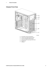
Front panel controls and indicators B. 5.25-inch removable media drive bays C. 3.5-inch removable media drive bay D. USB port Intel® Entry Server Chassis SC5275-E User Guide 2 Security lock F. Internal hard drive bay cage (behind door) E. 1 Chassis Description Chassis Front View A B C D E F TP00053 A.
Front panel controls and indicators B. 5.25-inch removable media drive bays C. 3.5-inch removable media drive bay D. USB port Intel® Entry Server Chassis SC5275-E User Guide 2 Security lock F. Internal hard drive bay cage (behind door) E. 1 Chassis Description Chassis Front View A B C D E F TP00053 A.
User Guide
Page 21
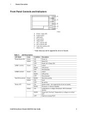
... button D. Sleep button F. Fan fault; Status LED TP00080 * Some items may not be supported by all server boards. Power / sleep LED B. CPU/Terminator missing Power fault; Temperature or voltage non-critical fault Fatal error during POST Intel® Entry Server Chassis SC5275-E User Guide 3 1 Chassis Description Front Panel Controls and Indicators A B C D E F G H I . Power button C. Hard drive activity LED...
... button D. Sleep button F. Fan fault; Status LED TP00080 * Some items may not be supported by all server boards. Power / sleep LED B. CPU/Terminator missing Power fault; Temperature or voltage non-critical fault Fatal error during POST Intel® Entry Server Chassis SC5275-E User Guide 3 1 Chassis Description Front Panel Controls and Indicators A B C D E F G H I . Power button C. Hard drive activity LED...
User Guide
Page 22
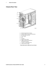
Alternate ICMB or external SCSI knockout C. Fan F. I . Intel® Entry Server Chassis SC5275-E User Guide 4 Serial B port knockout J. Alternate Serial B port knockout B. 1 Chassis Description Chassis Rear View A B C D E F TP00834 A. Location to install padlock loop K. Expansion slot covers H. Chassis intrusion switch * Items shown may be different in your chassis. Power supply E. ICMB or external SCSI knockout I /O ports* G. AC input power connector D.
Alternate ICMB or external SCSI knockout C. Fan F. I . Intel® Entry Server Chassis SC5275-E User Guide 4 Serial B port knockout J. Alternate Serial B port knockout B. 1 Chassis Description Chassis Rear View A B C D E F TP00834 A. Location to install padlock loop K. Expansion slot covers H. Chassis intrusion switch * Items shown may be different in your chassis. Power supply E. ICMB or external SCSI knockout I /O ports* G. AC input power connector D.

User Guide
Page 23
The drives are included with all server boards. Order Code AXX6SCSIDB AXX6SATADB APT2WKTCOOLKIT AXX2ICMBKIT AXXEXTSCSICBL Intel® Entry Server Chassis SC5275-E User Guide 5 Five bays are installed into a removable hard drive bay cage that consume up to two half-height peripherals. 3.5-inch Hard Drive Bays The chassis supports up to 18 Watts of spares and accessories, see http...
The drives are included with all server boards. Order Code AXX6SCSIDB AXX6SATADB APT2WKTCOOLKIT AXX2ICMBKIT AXXEXTSCSICBL Intel® Entry Server Chassis SC5275-E User Guide 5 Five bays are installed into a removable hard drive bay cage that consume up to two half-height peripherals. 3.5-inch Hard Drive Bays The chassis supports up to 18 Watts of spares and accessories, see http...
User Guide
Page 24
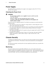
... in your region. The connector that the user can be an IEC 320, sheet C13, type female connector. This intrusion switch can be readily accessible. Intel® Entry Server Chassis SC5275-E User Guide 6 Checking the Power Cord WARNING Do not attempt to comply with the AC wall outlet in a number of the...
... in your region. The connector that the user can be an IEC 320, sheet C13, type female connector. This intrusion switch can be readily accessible. Intel® Entry Server Chassis SC5275-E User Guide 6 Checking the Power Cord WARNING Do not attempt to comply with the AC wall outlet in a number of the...
User Guide
Page 25
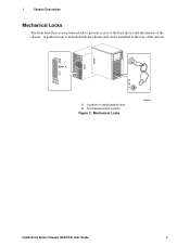
A B A. Front bezel locked position Figure 2. Mechanical Locks TP00055 Intel® Entry Server Chassis SC5275-E User Guide 7 Location to the hard drives and the interior of the chassis. 1 Chassis Description Mechanical Locks The front bezel has a two-position lock to prevent access to install padlock loop B. A padlock loop is included with the chassis and can be installed at the rear of the chassis.
A B A. Front bezel locked position Figure 2. Mechanical Locks TP00055 Intel® Entry Server Chassis SC5275-E User Guide 7 Location to the hard drives and the interior of the chassis. 1 Chassis Description Mechanical Locks The front bezel has a two-position lock to prevent access to install padlock loop B. A padlock loop is included with the chassis and can be installed at the rear of the chassis.

User Guide
Page 27
... 4), it is necessary to all peripheral devices connected to set the server up for any reason, observe these guidelines to chassis ground-any unpainted metal surface-when handling components. Intel® Entry Server Chassis SC5275-E User Guide 9 Safety: Before You Remove the Access Covers Before removing...non-compliant with this assembly. Turn off all of the chassis. 2 Setting Up the Chassis 2 Setting Up the Chassis This chapter describes how to the server. Follow these safety guidelines: Turn off the server by wearing an antistatic wrist strap attached to meet and...
... 4), it is necessary to all peripheral devices connected to set the server up for any reason, observe these guidelines to chassis ground-any unpainted metal surface-when handling components. Intel® Entry Server Chassis SC5275-E User Guide 9 Safety: Before You Remove the Access Covers Before removing...non-compliant with this assembly. Turn off all of the chassis. 2 Setting Up the Chassis 2 Setting Up the Chassis This chapter describes how to the server. Follow these safety guidelines: Turn off the server by wearing an antistatic wrist strap attached to meet and...

User Guide
Page 28
... to ESD. CAUTIONS ESD can result. They can damage system parts. After removing a board from its protective wrapper or from the wall outlet or the chassis. Intel® Entry Server Chassis SC5275-E User Guide 10 Otherwise, personal injury or equipment damage can damage disk drives, boards, and other parts. Do not touch the connector contacts. If...
... to ESD. CAUTIONS ESD can result. They can damage system parts. After removing a board from its protective wrapper or from the wall outlet or the chassis. Intel® Entry Server Chassis SC5275-E User Guide 10 Otherwise, personal injury or equipment damage can damage disk drives, boards, and other parts. Do not touch the connector contacts. If...
User Guide
Page 29
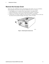
...upward, straight away from the notches in the top and bottom edges of the chassis. Set the cover aside. 2 1 1 3 2 TP00057 Figure 3. For ease of installation, before beginning lay the chassis on its right side, with the left to disengage the rows of this ...chapter. 2 Setting Up the Chassis Remove the Access Cover Observe the safety and ESD precautions at the beginning of tabs from the chassis, to the unlocked position (number 2 in the figure). 3. Removing the Access Cover Intel® Entry Server Chassis SC5275...
...upward, straight away from the notches in the top and bottom edges of the chassis. Set the cover aside. 2 1 1 3 2 TP00057 Figure 3. For ease of installation, before beginning lay the chassis on its right side, with the left to disengage the rows of this ...chapter. 2 Setting Up the Chassis Remove the Access Cover Observe the safety and ESD precautions at the beginning of tabs from the chassis, to the unlocked position (number 2 in the figure). 3. Removing the Access Cover Intel® Entry Server Chassis SC5275...

