
Product Guide
Page 3
... and Component Locations 20 Processor ...21 Memory ...22 Peripherals ...24 Super I/O Chip...24 Add-in Board Slots ...24 Video ...25 SCSI Controller ...25 IDE Controller...26 Keyboard and Mouse ...26 Server Management...27 Baseboard Management Controller (BMC 27 System Security ...28 Mechanical Locks and Monitoring 28 Software Locks via the SSU or...
... and Component Locations 20 Processor ...21 Memory ...22 Peripherals ...24 Super I/O Chip...24 Add-in Board Slots ...24 Video ...25 SCSI Controller ...25 IDE Controller...26 Keyboard and Mouse ...26 Server Management...27 Baseboard Management Controller (BMC 27 System Security ...28 Mechanical Locks and Monitoring 28 Software Locks via the SSU or...

Product Guide
Page 4
... Management Port (EMP) Console 57 How the EMP Console Works 58 EMP Console Requirements 60 Setting Up the Server for the EMP 60 Main EMP Console Window 61 Server Control Operations 63 Phonebook ...65 Management Plug-ins 66 FRU and SDR Load Utility 69 When to Run the...Update Utility 77 Installing Video Drivers...77 Using the Symbios SCSI Utility 77 Running the SCSI Utility 77 4 Exchanging SCSI Hard Drives and Power Supplies SCSI Hard Disk Drives ...79 Mounting a SCSI Hard Disk Drive in a Plastic Carrier 79 Hot-swapping a SCSI Hard Disk Drive 80 Installing Heatsinks on High-Power ...
... Management Port (EMP) Console 57 How the EMP Console Works 58 EMP Console Requirements 60 Setting Up the Server for the EMP 60 Main EMP Console Window 61 Server Control Operations 63 Phonebook ...65 Management Plug-ins 66 FRU and SDR Load Utility 69 When to Run the...Update Utility 77 Installing Video Drivers...77 Using the Symbios SCSI Utility 77 Running the SCSI Utility 77 4 Exchanging SCSI Hard Drives and Power Supplies SCSI Hard Disk Drives ...79 Mounting a SCSI Hard Disk Drive in a Plastic Carrier 79 Hot-swapping a SCSI Hard Disk Drive 80 Installing Heatsinks on High-Power ...

Product Guide
Page 6
... SMM Connector...142 IPMB...143 VGA Video Port ...143 Keyboard and Mouse 144 Parallel Port ...144 Serial Ports A and B 145 Universal Serial Bus 145 Narrow SCSI...146 Wide SCSI ...147 IDE ...148 vi
... SMM Connector...142 IPMB...143 VGA Video Port ...143 Keyboard and Mouse 144 Parallel Port ...144 Serial Ports A and B 145 Universal Serial Bus 145 Narrow SCSI...146 Wide SCSI ...147 IDE ...148 vi

Product Guide
Page 12
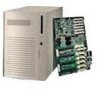
... A front subchassis and an electronics bay (at the rear of the chassis. Chassis Feature Summary Feature Description Drives Installed: 1.44 MB, 3.5-inch diskette drive, accessible from front subchassis. Power supply Up to two drives without the backplane. The removable front panel provides...Expansion capacity: Three 5.25-inch-wide bays that does not have a slot cover installed. Also, one -inch drives with an optional SCSI backplane, or up to six one externally accessible bay can be used; Chassis Feature Summary The system's galvanized metal chassis minimizes EMI and...
... A front subchassis and an electronics bay (at the rear of the chassis. Chassis Feature Summary Feature Description Drives Installed: 1.44 MB, 3.5-inch diskette drive, accessible from front subchassis. Power supply Up to two drives without the backplane. The removable front panel provides...Expansion capacity: Three 5.25-inch-wide bays that does not have a slot cover installed. Also, one -inch drives with an optional SCSI backplane, or up to six one externally accessible bay can be used; Chassis Feature Summary The system's galvanized metal chassis minimizes EMI and...

Product Guide
Page 15
Main chassis D. Foam fan housing cover J OM08017 15 Chassis Side View A B CD E FG H I . Power backplane E. Baseboard G. Lift-out electronics bay H. 5.25" device bay I LK Figure 5. Chassis Side View A. Diskette drive C. Power supply(s) F. Foam fan housing L. Foam cover K. SCSI hard drive bay J. Front swing-out subchassis B.
Main chassis D. Foam fan housing cover J OM08017 15 Chassis Side View A B CD E FG H I . Power backplane E. Baseboard G. Lift-out electronics bay H. 5.25" device bay I LK Figure 5. Chassis Side View A. Diskette drive C. Power supply(s) F. Foam fan housing L. Foam cover K. SCSI hard drive bay J. Front swing-out subchassis B.

Product Guide
Page 16
...Device Bays The chassis has three 5.25-inch half-height bays that are mounted in the 3.5-inch peripheral bay supports 720 KB, and 1.44 MB media. An optional hot-swap-capable backplane can be specified to install a Redundant Array of the hot-swap implementation, a drive carrier is ... carrier snaps into the chassis. The drive is required. The drives are accessible from the front of the system. A software implementation with onboard SCSI or an add-in an optional kit. • For information on how and when to install extra fans, see "Installing Heatsinks on page 106...
...Device Bays The chassis has three 5.25-inch half-height bays that are mounted in the 3.5-inch peripheral bay supports 720 KB, and 1.44 MB media. An optional hot-swap-capable backplane can be specified to install a Redundant Array of the hot-swap implementation, a drive carrier is ... carrier snaps into the chassis. The drive is required. The drives are accessible from the front of the system. A software implementation with onboard SCSI or an add-in an optional kit. • For information on how and when to install extra fans, see "Installing Heatsinks on page 106...

Product Guide
Page 19
... 2 MB of error correcting code (ECC) memory. Two serial ports, 9-pin (serial port A is automatically programmed by the processor's VID pins to 4 GB of video memory. 2 Baseboard Description Baseboard Features Table 3. SCSI System I /O. 19 Server Management ...Thermal/voltage monitoring and error handling. Symbios SYM53C896-dual-channel wide LVD/SE (Ultra2/Ultra) SCSI controller on PCI-A bus providing support for external expansion....
... 2 MB of error correcting code (ECC) memory. Two serial ports, 9-pin (serial port A is automatically programmed by the processor's VID pins to 4 GB of video memory. 2 Baseboard Description Baseboard Features Table 3. SCSI System I /O. 19 Server Management ...Thermal/voltage monitoring and error handling. Symbios SYM53C896-dual-channel wide LVD/SE (Ultra2/Ultra) SCSI controller on PCI-A bus providing support for external expansion....

Product Guide
Page 20
... 3 Slot 2 connector (J9D1) Z. Main power connector, secondary (J9D2) AA. SMBus connector (J9F2) HH. SMM connector (J8H1) MM.Wide SCSI A connector (J9H2) 20 ISA slot (J1J1) H. VRM connector for processors 2 and 1 (J4A2) U. Diskette drive connector (J9E3) EE. Auxiliary...DD CC BB AA Z Y X W V H I . System jumpers (J6J1) C. Serial port connector (J1B2) N. Processor 1 Slot 2 connector (J9A1) W. Wide SCSI B connector (J9J1) B. Wake on LAN† technology connector (J4H1) G. USB external connector (J1A1) P. VRM connector for processor 3 (J4C1) S. VRM connector for ...
... 3 Slot 2 connector (J9D1) Z. Main power connector, secondary (J9D2) AA. SMBus connector (J9F2) HH. SMM connector (J8H1) MM.Wide SCSI A connector (J9H2) 20 ISA slot (J1J1) H. VRM connector for processors 2 and 1 (J4A2) U. Diskette drive connector (J9E3) EE. Auxiliary...DD CC BB AA Z Y X W V H I . System jumpers (J6J1) C. Serial port connector (J1B2) N. Processor 1 Slot 2 connector (J9A1) W. Wide SCSI B connector (J9J1) B. Wake on LAN† technology connector (J4H1) G. USB external connector (J1A1) P. VRM connector for processor 3 (J4C1) S. VRM connector for ...

Product Guide
Page 24
...8 MB/sec • 8- Parallel Port The 25/15-pin connector stacks the parallel port over the VGA. PCI features: • 33 MHz bus speed • 32-bit memory addressing • 5 V signaling environment • Burst transfers of up to one ISA slot that is full-length if the wide SCSI-B ...PCI-A1 supports half-length boards only. Peripherals Super I /O chip, Baseboard Management Controller (BMC), and flash memory for each port can be programmed to 133 MB/sec • 8-, 16-, or 32-bit data transfers • Plug and Play ready • Parity enabled 24 or 16-bit data transfers •...
...8 MB/sec • 8- Parallel Port The 25/15-pin connector stacks the parallel port over the VGA. PCI features: • 33 MHz bus speed • 32-bit memory addressing • 5 V signaling environment • Burst transfers of up to one ISA slot that is full-length if the wide SCSI-B ...PCI-A1 supports half-length boards only. Peripherals Super I /O chip, Baseboard Management Controller (BMC), and flash memory for each port can be programmed to 133 MB/sec • 8-, 16-, or 32-bit data transfers • Plug and Play ready • Parity enabled 24 or 16-bit data transfers •...

Product Guide
Page 25
... in the 5.25-inch drive bays. All drives on the bus must be disabled. 25 The SCSI bus is fully compatible with these connectors is identical, capable of 132 MB/sec using either 8- Video The onboard, integrated Cirrus Logic CL-GD5480 64-bit VGA chip contains an... PCI up to this system. The SVGA controller supports analog VGA monitors (single and multiple frequency, interlaced and noninterlaced) with 2 MB of data. The narrow SCSI comes in some video resolutions. Each controller has its appropriate speed. It also provides hardware-accelerated bit block transfers (BITBLT) of...
... in the 5.25-inch drive bays. All drives on the bus must be disabled. 25 The SCSI bus is fully compatible with these connectors is identical, capable of 132 MB/sec using either 8- Video The onboard, integrated Cirrus Logic CL-GD5480 64-bit VGA chip contains an... PCI up to this system. The SVGA controller supports analog VGA monitors (single and multiple frequency, interlaced and noninterlaced) with 2 MB of data. The narrow SCSI comes in some video resolutions. Each controller has its appropriate speed. It also provides hardware-accelerated bit block transfers (BITBLT) of...

Product Guide
Page 31
Or, you can be run the SSU to configure or view the settings of the SCSI host adapters and onboard SCSI devices in boards, viewing the system event log (SEL), setting boot device priority, or setting system security options. FRUSDR Load Utility Use to the Clear ... it. Firmware Update Utility Use to boot. Enter BIOS Setup during BIOS POST. this is disabled or misconfigured, use Setup to access and monitor the server remotely. The SSU can move the CMOS jumper on screen) 31 Table 7. For the procedure to make a set DOS-bootable diskettes. See the printed Quick...
Or, you can be run the SSU to configure or view the settings of the SCSI host adapters and onboard SCSI devices in boards, viewing the system event log (SEL), setting boot device priority, or setting system security options. FRUSDR Load Utility Use to the Clear ... it. Firmware Update Utility Use to boot. Enter BIOS Setup during BIOS POST. this is disabled or misconfigured, use Setup to access and monitor the server remotely. The SSU can move the CMOS jumper on screen) 31 Table 7. For the procedure to make a set DOS-bootable diskettes. See the printed Quick...

Product Guide
Page 32
... processors, memory, keyboard, and most installed peripheral devices. Note the screen display and write down the beep code you do not enter the SCSI utility, the boot process continues. 5. If you hear; After POST completes, the system beeps once. Also see Chapter 7, "Solving Problems...memory installed. During the memory test, POST displays the amount of beep codes and error messages that requires immediate attention. Press if SCSI devices are installed. Turn on the video display screen, the speaker beeps twice as the message appears. Then this message appears: ...
... processors, memory, keyboard, and most installed peripheral devices. Note the screen display and write down the beep code you do not enter the SCSI utility, the boot process continues. 5. If you hear; After POST completes, the system beeps once. Also see Chapter 7, "Solving Problems...memory installed. During the memory test, POST displays the amount of beep codes and error messages that requires immediate attention. Press if SCSI devices are installed. Turn on the video display screen, the speaker beeps twice as the message appears. Then this message appears: ...

Product Guide
Page 33
... describes the BIOS Setup options. the rest of the configuration values in RTC) • Configure IDE hard drive • Specify boot device sequence • Enable SCSI BIOS Run SSU, not Setup: you must run the SSU instead of choices selected by the BIOS resource manager Record Your Setup Settings If the...
... describes the BIOS Setup options. the rest of the configuration values in RTC) • Configure IDE hard drive • Specify boot device sequence • Enable SCSI BIOS Run SSU, not Setup: you must run the SSU instead of choices selected by the BIOS resource manager Record Your Setup Settings If the...

Product Guide
Page 34
Server Menu • System Management • Console Redirection 5. Security Menu 4. Exit Menu To: Get general help Move between menus Go to the previous item Go to ... IDE Master and Slave • Keyboard Features 2. Boot Menu • Boot Device Priority • Hard Drive 6. Advanced Menu • PCI Configuration PCI Device, Embedded SCSI PCI Devices • I/O Device Configuration • Advanced Chipset Control 3. In the three conditions listed above, after rebooting, you will see this prompt: Press to...
Server Menu • System Management • Console Redirection 5. Security Menu 4. Exit Menu To: Get general help Move between menus Go to the previous item Go to ... IDE Master and Slave • Keyboard Features 2. Boot Menu • Boot Device Priority • Hard Drive 6. Advanced Menu • PCI Configuration PCI Device, Embedded SCSI PCI Devices • I/O Device Configuration • Advanced Chipset Control 3. In the three conditions listed above, after rebooting, you will see this prompt: Press to...

Product Guide
Page 38
... time, in units of PCI bus clocks, that a device can be master on a PCI bus. Enables all devices other than the onboard SCSI controllers. PCI Configuration Submenu The PCI Configuration Menu contains selections that a device can be master on a PCI bus. PCI Device, Embedded... SCSI Submenu Table 12. Enable Master Disabled Enabled Enables selected device as a PCI bus master. PCI Devices Submenu Table 13. Typically, option ROM...
... time, in units of PCI bus clocks, that a device can be master on a PCI bus. Enables all devices other than the onboard SCSI controllers. PCI Configuration Submenu The PCI Configuration Menu contains selections that a device can be master on a PCI bus. PCI Device, Embedded... SCSI Submenu Table 12. Enable Master Disabled Enabled Enables selected device as a PCI bus master. PCI Devices Submenu Table 13. Typically, option ROM...

Product Guide
Page 77
... advantage of the features of the *.hex file name, because you want to : • Change default values • Check and/or change SCSI device settings that you will ask for use with those of other operating systems, see your OS instructions for information on the system board. Press...cords from the system and wait 60 seconds. 12. Once the operational code has been updated and verified, press any diskettes in the server Running the SCSI Utility When this message appears on the diskette. Use the utility to configure. 77 Press to exit the program. 10. Shut the system...
... advantage of the features of the *.hex file name, because you want to : • Change default values • Check and/or change SCSI device settings that you will ask for use with those of other operating systems, see your OS instructions for information on the system board. Press...cords from the system and wait 60 seconds. 12. Once the operational code has been updated and verified, press any diskettes in the server Running the SCSI Utility When this message appears on the diskette. Use the utility to configure. 77 Press to exit the program. 10. Shut the system...

Product Guide
Page 79
... disk drives. Mounting a SCSI Hard Disk Drive in this manual only at an ESD-protected workstation. However, we recommend doing all procedures in a Plastic Carrier 1. OM08043 Figure 18. Using four screws of the server-any unpainted metal surface-when handling components. CAUTION Electrostatic... discharge (ESD) and ESD protection: ESD can withstand normal levels of approved SCSI devices. If one is near the top surface of the drive...
... disk drives. Mounting a SCSI Hard Disk Drive in this manual only at an ESD-protected workstation. However, we recommend doing all procedures in a Plastic Carrier 1. OM08043 Figure 18. Using four screws of the server-any unpainted metal surface-when handling components. CAUTION Electrostatic... discharge (ESD) and ESD protection: ESD can withstand normal levels of approved SCSI devices. If one is near the top surface of the drive...

Product Guide
Page 80
... Chassis A. Check the bank of yellow LEDs on the front panel monitors the drive status of each drive in the upper-most drive. Hot-swapping a SCSI Hard Disk Drive A bank of six yellow LEDs on the front panel to determine which drive is bad. 5. You DO NOT need to shut the...
... Chassis A. Check the bank of yellow LEDs on the front panel monitors the drive status of each drive in the upper-most drive. Hot-swapping a SCSI Hard Disk Drive A bank of six yellow LEDs on the front panel to determine which drive is bad. 5. You DO NOT need to shut the...

Product Guide
Page 82
... to the drive. 3. This requires that you work inside the chassis and that the three screw holes in a Plastic Carrier" on those drives. See "Mounting a SCSI Hard Disk Drive in the heatsink align with the fins extending along the side and the top of this document, "Service Technician's Guide." 1. CAUTION If... the drive into the hot-docking bay, you must also install additional system fans. Installing Heatsinks on High-Power Drives If you plan to use SCSI drives whose power exceeds 15 watts, you must install heatsinks on page 79.
... to the drive. 3. This requires that you work inside the chassis and that the three screw holes in a Plastic Carrier" on those drives. See "Mounting a SCSI Hard Disk Drive in the heatsink align with the fins extending along the side and the top of this document, "Service Technician's Guide." 1. CAUTION If... the drive into the hot-docking bay, you must also install additional system fans. Installing Heatsinks on High-Power Drives If you plan to use SCSI drives whose power exceeds 15 watts, you must install heatsinks on page 79.
Product Guide
Page 97
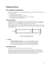
... do not. For proper IDE operation, note the cable length specified in the internal bays (1-inch or 1.6-inch high) • The combination of the SCSI cable. If only one drive is installed, it in the lowest internal drive bay to reuse the interrupt for that controller, you can install depends... 29. Because we recommend placing it must be unterminated except the peripheral at the end of devices you must be connected at the end of SCSI and IDE devices IDE Requirements An 18-inch long IDE cable that the last device on : • The number supported by configuring the SSU ...
... do not. For proper IDE operation, note the cable length specified in the internal bays (1-inch or 1.6-inch high) • The combination of the SCSI cable. If only one drive is installed, it in the lowest internal drive bay to reuse the interrupt for that controller, you can install depends... 29. Because we recommend placing it must be unterminated except the peripheral at the end of devices you must be connected at the end of SCSI and IDE devices IDE Requirements An 18-inch long IDE cable that the last device on : • The number supported by configuring the SSU ...