
Product Specification
Page 1
SAI2 Server Board Technical Product Specification Revision 1.0 November 2001 Enterprise Platforms and Services Marketing
SAI2 Server Board Technical Product Specification Revision 1.0 November 2001 Enterprise Platforms and Services Marketing

Product Specification
Page 2
Modifications SAI2 Server Board TPS ii Revision 1.0 Revision History Revision History Date Revision Number November 2001 1.0 Initial Release.
Modifications SAI2 Server Board TPS ii Revision 1.0 Revision History Revision History Date Revision Number November 2001 1.0 Initial Release.

Product Specification
Page 3
...have no responsibility whatsoever for such products, Intel assumes no liability whatsoever, and Intel disclaims any express or implied warranty, relating to sale and/or use in medical, life saving, or life sustaining applications. SAI2 Server Board TPS Disclaimers Disclaimers Information in this ...as the property of any time, without notice. Designers must not rely on request. The SAI2 Server Board may make changes to fitness for use of Intel products including liability or warranties relating to specifications and product descriptions at any features or instructions ...
...have no responsibility whatsoever for such products, Intel assumes no liability whatsoever, and Intel disclaims any express or implied warranty, relating to sale and/or use in medical, life saving, or life sustaining applications. SAI2 Server Board TPS Disclaimers Disclaimers Information in this ...as the property of any time, without notice. Designers must not rely on request. The SAI2 Server Board may make changes to fitness for use of Intel products including liability or warranties relating to specifications and product descriptions at any features or instructions ...

Product Specification
Page 4
... 1.0 Introduction...1 1.1 Purpose...1 1.2 Audience ...1 1.3 SAI2 Server Board Feature Overview 1 1.4 SAI2 Server Board Block Diagram 2 2. SAI2 Server Board Architecture Overview 3 2.1 Intel® Pentium® III Processor Subsystem 3 2.1.1 Supported Processor Types 3 2.1.2 Dual Processor Operation 3 2.1.3 PGA370 Socket ...4 2.1.4 Processor Bus Termination / Regulation / Power 4 2.1.5 APIC Bus ...4 2.1.6 Boxed Processors...4 2.2 ServerWorks ServerSet III LE Chipset 5 2.3 Memory ...5 2.4 PCI I/O Subsystem...6 2.4.1 64-bit / 66 MHz PCI Subsystem 6 2.4.2 32-bit/33 MHz PCI...
... 1.0 Introduction...1 1.1 Purpose...1 1.2 Audience ...1 1.3 SAI2 Server Board Feature Overview 1 1.4 SAI2 Server Board Block Diagram 2 2. SAI2 Server Board Architecture Overview 3 2.1 Intel® Pentium® III Processor Subsystem 3 2.1.1 Supported Processor Types 3 2.1.2 Dual Processor Operation 3 2.1.3 PGA370 Socket ...4 2.1.4 Processor Bus Termination / Regulation / Power 4 2.1.5 APIC Bus ...4 2.1.6 Boxed Processors...4 2.2 ServerWorks ServerSet III LE Chipset 5 2.3 Memory ...5 2.4 PCI I/O Subsystem...6 2.4.1 64-bit / 66 MHz PCI Subsystem 6 2.4.2 32-bit/33 MHz PCI...

Product Specification
Page 5
SAI2 Server Board TPS Table of Contents 3.1 BIOS Overview...19 3.1.1 System BIOS ...20 3.1.2 Flash Update Utility 20 3.2 Setup Utility ...21 3.2.1 Configuration Utilities Overview 21 3.2.2 Setup Utility Operation 21 3.3 CMOS Memory Definition 32 3.4 CMOS Default Override 32 3.5 Flash Update Utility ...33 3.5.1 Loading the System BIOS 33 3.5.2 Customization ...34 3.5.3 Language Area ...37 3.5.4 Recovery Mode...37... 51 4.3.8 Keyboard (KB) and Mouse (MS) Connectors 52 4.3.9 Parallel Port (LPT1 52 4.3.10 Serial Ports COM1 and COM2 52 4.3.11 RJ-45 LAN Connector (J2 53 Revision 1.0 v
SAI2 Server Board TPS Table of Contents 3.1 BIOS Overview...19 3.1.1 System BIOS ...20 3.1.2 Flash Update Utility 20 3.2 Setup Utility ...21 3.2.1 Configuration Utilities Overview 21 3.2.2 Setup Utility Operation 21 3.3 CMOS Memory Definition 32 3.4 CMOS Default Override 32 3.5 Flash Update Utility ...33 3.5.1 Loading the System BIOS 33 3.5.2 Customization ...34 3.5.3 Language Area ...37 3.5.4 Recovery Mode...37... 51 4.3.8 Keyboard (KB) and Mouse (MS) Connectors 52 4.3.9 Parallel Port (LPT1 52 4.3.10 Serial Ports COM1 and COM2 52 4.3.11 RJ-45 LAN Connector (J2 53 Revision 1.0 v

Product Specification
Page 6
Table of Contents SAI2 Server Board TPS 4.3.12 USB Connectors (J2 53 4.3.13 IDE Connectors (PRI_IDE, SEC_IDE 53 4.3.14 32-Bit PCI Connectors 54 4.3.15 64-Bit PCI Connectors 55 4.3.16 Front Panel 24-pin Connector Pinout (FRONT_PANEL_HDR 56 5. Baseboard Specifications ... Ensure EMC ...63 7.2.2 Ensure Host Computer and Accessory Module Certifications 63 7.2.3 Prevent Power Supply Overload 64 7.2.4 Place Battery Marking on Computer 64 7.2.5 Use Only for Intended Applications 65 7.2.6 Installation Precautions 65 Glossary...I Reference Documents ...III Index...IV vi Revision 1.0
Table of Contents SAI2 Server Board TPS 4.3.12 USB Connectors (J2 53 4.3.13 IDE Connectors (PRI_IDE, SEC_IDE 53 4.3.14 32-Bit PCI Connectors 54 4.3.15 64-Bit PCI Connectors 55 4.3.16 Front Panel 24-pin Connector Pinout (FRONT_PANEL_HDR 56 5. Baseboard Specifications ... Ensure EMC ...63 7.2.2 Ensure Host Computer and Accessory Module Certifications 63 7.2.3 Prevent Power Supply Overload 64 7.2.4 Place Battery Marking on Computer 64 7.2.5 Use Only for Intended Applications 65 7.2.6 Installation Precautions 65 Glossary...I Reference Documents ...III Index...IV vi Revision 1.0

Product Specification
Page 7
Video Controller PCI Signals 9 Figure 4. SAI2 Baseboard Interrupt Routing Diagram (Symmetric Mode 16 Figure 6. SAI2 Server Board Jumper and Connector Locations 45 Figure 7. SAI2 Server Board TPS List of Figures List of Figures Figure 1. Embedded NIC PCI Signals 7 Figure 3. SAI2 Baseboard Interrupt Routing Diagram (PIC Mode 15 Figure 5. SAI2 Server Board Block Diagram 2 Figure 2. I/O Back Panel Connectors 46 Revision 1.0 vii
Video Controller PCI Signals 9 Figure 4. SAI2 Baseboard Interrupt Routing Diagram (Symmetric Mode 16 Figure 6. SAI2 Server Board Jumper and Connector Locations 45 Figure 7. SAI2 Server Board TPS List of Figures List of Figures Figure 1. Embedded NIC PCI Signals 7 Figure 3. SAI2 Baseboard Interrupt Routing Diagram (PIC Mode 15 Figure 5. SAI2 Server Board Block Diagram 2 Figure 2. I/O Back Panel Connectors 46 Revision 1.0 vii

Product Specification
Page 8
... 17 Table 6. Memory Reconfiguration Submenu Selections 26 Table 12. CPU Reconfiguration Submenu Selections 26 Table 13. Server Menu Selections 30 Table 20. Exit Menu Selections 32 Table 25. Wake On Events Submenu Selections 31 Table 21. SAI2 Server Board Supported Processors 3 Table 2. Boot Device Priority Selections 31 Table 22. Advanced Submenu Selections 25 Table...
... 17 Table 6. Memory Reconfiguration Submenu Selections 26 Table 12. CPU Reconfiguration Submenu Selections 26 Table 13. Server Menu Selections 30 Table 20. Exit Menu Selections 32 Table 25. Wake On Events Submenu Selections 31 Table 21. SAI2 Server Board Supported Processors 3 Table 2. Boot Device Priority Selections 31 Table 22. Advanced Submenu Selections 25 Table...

Product Specification
Page 9
...50 Table 38. RJ-45 LAN Connector Signals 53 Table 44. Front Panel 24-pin Connector Pinout 56 Table 49. Estimated MTBF Calculated Numbers for SAI2/SC5100 59 Table 50. ... Pinout 51 Table 40. IDE Connector Pinout 53 Table 46. 32-Bit PCI Connector Pinout 54 Table 47. 64-Bit PCI Connctor Pinout 55 Table 48. USB Connectors...53 Table...SAI2 Server Board Calculated Power Consumption 60 Table 52. Safety Regulations 62 Table 54. SAI2 Server Board Measured Power Consumption 61 Table 53. EMC Regulations...62 Revision 1.0 ix SAI2 Server Board TPS List of Tables Table 32...
...50 Table 38. RJ-45 LAN Connector Signals 53 Table 44. Front Panel 24-pin Connector Pinout 56 Table 49. Estimated MTBF Calculated Numbers for SAI2/SC5100 59 Table 50. ... Pinout 51 Table 40. IDE Connector Pinout 53 Table 46. 32-Bit PCI Connector Pinout 54 Table 47. 64-Bit PCI Connctor Pinout 55 Table 48. USB Connectors...53 Table...SAI2 Server Board Calculated Power Consumption 60 Table 52. Safety Regulations 62 Table 54. SAI2 Server Board Measured Power Consumption 61 Table 53. EMC Regulations...62 Revision 1.0 ix SAI2 Server Board TPS List of Tables Table 32...

Product Specification
Page 10
List of Tables SAI2 Server Board TPS < This page intentionally left blank. > x Revision 1.0
List of Tables SAI2 Server Board TPS < This page intentionally left blank. > x Revision 1.0
Product Specification
Page 11
...* ServerSet* III LE chipset - 133-MHz Front Side Bus (FSB) Capability - Four 32-bit, 33-MHz, 5-V keyed PCI expansion slots - Four DIMM slots allow a maxiumum installed memory of the SAI2 server board. ECC single-bit correction, and multiple-bit detection • 64-bit, 66-MHz, 3.3-V keyed PCI segment with the personal computer, Intel server architecture and the...
...* ServerSet* III LE chipset - 133-MHz Front Side Bus (FSB) Capability - Four 32-bit, 33-MHz, 5-V keyed PCI expansion slots - Four DIMM slots allow a maxiumum installed memory of the SAI2 server board. ECC single-bit correction, and multiple-bit detection • 64-bit, 66-MHz, 3.3-V keyed PCI segment with the personal computer, Intel server architecture and the...
Product Specification
Page 12
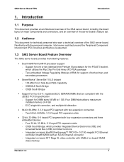
... SAI2 Server Board Block Diagram The SAI2 server board offers a "flat" design, with two embedded devices - SAI2 Server Board Block Diagram 2x 64bit/66MHz PCI Slots FCPGA Tualatin FCPGA Tualatin 133MHz System Bus 4x 32bit/33MHz PCI Slots PCI (64/66) PCI (32/33) MLCE-HT Up to 4GB ECC...Dual Universal Serial Bus (USB) ports • Two IDE connectors • Flash BIOS support for all PC-compatible I /O Floppy Keyboard, Mouse Serial Ports Parallel Port X-BUS NvRAM (32KB) Figure 1. Super I/O Controller (PC87417) that provides all of the server board. Introduction SAI2 Server...
... SAI2 Server Board Block Diagram The SAI2 server board offers a "flat" design, with two embedded devices - SAI2 Server Board Block Diagram 2x 64bit/66MHz PCI Slots FCPGA Tualatin FCPGA Tualatin 133MHz System Bus 4x 32bit/33MHz PCI Slots PCI (64/66) PCI (32/33) MLCE-HT Up to 4GB ECC...Dual Universal Serial Bus (USB) ports • Two IDE connectors • Flash BIOS support for all PC-compatible I /O Floppy Keyboard, Mouse Serial Ports Parallel Port X-BUS NvRAM (32KB) Figure 1. Super I/O Controller (PC87417) that provides all of the server board. Introduction SAI2 Server...

Product Specification
Page 13
... Operation The Pentium III processor interface is based on a design that supports dual-processor operation with Intel Pentium III processors and the ServerWorks ServerSet III LE chipset. Revision 1.0 3 SAI2 Server Board TPS SAI2 Server Board Architecture Overview 2. The SAI2 server contains embedded devices for the SAI2 server board: Table 1. This package utilizes the same 370-pin zero-insertion force socket (PGA370...
... Operation The Pentium III processor interface is based on a design that supports dual-processor operation with Intel Pentium III processors and the ServerWorks ServerSet III LE chipset. Revision 1.0 3 SAI2 Server Board TPS SAI2 Server Board Architecture Overview 2. The SAI2 server contains embedded devices for the SAI2 server board: Table 1. This package utilizes the same 370-pin zero-insertion force socket (PGA370...

Product Specification
Page 14
... III processor for the PGA370 socket is recommended that has an integrated clip. Additional termination is provided on the processor. Intel boxed processors are implemented directly on the SAI2 server board for terminator-less operation when only one processor is installed. 2.1.5 APIC Bus Interrupt notification and generation for the PGA370 socket will keep...
... III processor for the PGA370 socket is recommended that has an integrated clip. Additional termination is provided on the processor. Intel boxed processors are implemented directly on the SAI2 server board for terminator-less operation when only one processor is installed. 2.1.5 APIC Bus Interrupt notification and generation for the PGA370 socket will keep...

Product Specification
Page 15
...Bridge is 64 MB using four DIMMs. Note: Neither PC100 DIMMs nor non-ECC DIMMs can be both a master and target on the Intel Pentium III processor. The CSB5 South Bridge provides a number of DIMMS, Intel recommends that ...64-bit, 66-MHz, Revision 2.2-compliant PCI bus and the 32-bit, 33-MHz, Revision 2.2-compliant PCI bus. The CNB30LE North Bridge is partitioned as four banks of registered SDRAM DIMMs, each request. A wide range of the PCI buses. SAI2 Server Board TPS SAI2 Server Board Architecture Overview 2.2 ServerWorks ServerSet III LE Chipset The ServerWorks ServerSet III LE...
...Bridge is 64 MB using four DIMMs. Note: Neither PC100 DIMMs nor non-ECC DIMMs can be both a master and target on the Intel Pentium III processor. The CSB5 South Bridge provides a number of DIMMS, Intel recommends that ...64-bit, 66-MHz, Revision 2.2-compliant PCI bus and the 32-bit, 33-MHz, Revision 2.2-compliant PCI bus. The CNB30LE North Bridge is partitioned as four banks of registered SDRAM DIMMs, each request. A wide range of the PCI buses. SAI2 Server Board TPS SAI2 Server Board Architecture Overview 2.2 ServerWorks ServerSet III LE Chipset The ServerWorks ServerSet III LE...

Product Specification
Page 16
...-to a peak of 132 MBps • 8-, 16-, or 32-bit data transfers • Plug-and-Play ready • Parity enabled 6 Revision 1.0 SAI2 Server Board Architecture Overview SAI2 Server Board TPS System memory begins at address 0 and is noncontiguous in the form of one 64-bit / 66-MHz bus segment and one 32-bit / 33-MHz bus segment.
...-to a peak of 132 MBps • 8-, 16-, or 32-bit data transfers • Plug-and-Play ready • Parity enabled 6 Revision 1.0 SAI2 Server Board Architecture Overview SAI2 Server Board TPS System memory begins at address 0 and is noncontiguous in the form of one 64-bit / 66-MHz bus segment and one 32-bit / 33-MHz bus segment.

Product Specification
Page 17
... TRDY_L IRDY_L STOP_L DEVSEL_L IDSEL REQ_L GNT_L PCI_CLK RST_L PERR_L SERR_L PCI_INT_L Figure 2. No external devices are included on the Intel® 82559 Fast Ethernet PCI Bus Controller. The network operating system communicates with the 82559 using a memory-mapped I/O ... PCI Local Area Network (LAN) controller for access to the PCI bus, and also enable back-to-back frame transmission within the minimum 960ns inter-frame spacing. SAI2 Server Board TPS SAI2 Server Board Architecture Overview 2.4.2.1 Network Interface Controller (NIC) The SAI2 server board includes a 10Base-T ...
... TRDY_L IRDY_L STOP_L DEVSEL_L IDSEL REQ_L GNT_L PCI_CLK RST_L PERR_L SERR_L PCI_INT_L Figure 2. No external devices are included on the Intel® 82559 Fast Ethernet PCI Bus Controller. The network operating system communicates with the 82559 using a memory-mapped I/O ... PCI Local Area Network (LAN) controller for access to the PCI bus, and also enable back-to-back frame transmission within the minimum 960ns inter-frame spacing. SAI2 Server Board TPS SAI2 Server Board Architecture Overview 2.4.2.1 Network Interface Controller (NIC) The SAI2 server board includes a 10Base-T ...
Product Specification
Page 18
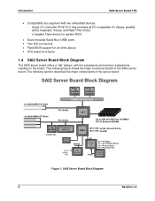
...ID. • Support for Wake-on-LAN (WOL) 2.4.2.2 Video Controller The SAI2 server board includes an ATI Rage XL video ...32-bit PCI Bus Master Interface (Direct Drive of Bus), compatible with PCI Bus Specification, revision 2.1 / 2.2 • Chained memory structure, with back-to-back transmit at 100 Mbps • Integrated physical interface to 16.7 million colors. The Rage XL, 64... x 32 SDRAM chip provides 8 MB of 32-bit PCI signals because it never acts as a PCI master. As a PCI slave, the device requires no arbitration or interrupts. 8 Revision 1.0 The SAI2 server board...
...ID. • Support for Wake-on-LAN (WOL) 2.4.2.2 Video Controller The SAI2 server board includes an ATI Rage XL video ...32-bit PCI Bus Master Interface (Direct Drive of Bus), compatible with PCI Bus Specification, revision 2.1 / 2.2 • Chained memory structure, with back-to-back transmit at 100 Mbps • Integrated physical interface to 16.7 million colors. The Rage XL, 64... x 32 SDRAM chip provides 8 MB of 32-bit PCI signals because it never acts as a PCI master. As a PCI slave, the device requires no arbitration or interrupts. 8 Revision 1.0 The SAI2 server board...

Product Specification
Page 19
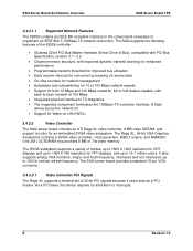
SAI2 Server Board TPS SAI2 Server Board Architecture Overview Rage XL AD[31::0] C/BE[3::0]_L PAR FRAME_L TRDY_L IRDY_L STOP_L DEVSEL_L IDSEL PCI_CLK RST_L PERR_L SERR_L PCI_INT_L Figure 3. Video Controller PCI ... 1110 1111 Command Type Interrupt Acknowledge Special Cycle I/O Read I/O Write Reserved Reserved Memory Read Memory Write Reserved Reserved Configuration Read Configuration Write Memory Read Multiple Dual Address Cycle Memory Read Line Memory Write and Invalidate Rage XL Support Target Master No No No No Yes No Yes No No No No...
SAI2 Server Board TPS SAI2 Server Board Architecture Overview Rage XL AD[31::0] C/BE[3::0]_L PAR FRAME_L TRDY_L IRDY_L STOP_L DEVSEL_L IDSEL PCI_CLK RST_L PERR_L SERR_L PCI_INT_L Figure 3. Video Controller PCI ... 1110 1111 Command Type Interrupt Acknowledge Special Cycle I/O Read I/O Write Reserved Reserved Memory Read Memory Write Reserved Reserved Configuration Read Configuration Write Memory Read Multiple Dual Address Cycle Memory Read Line Memory Write and Invalidate Rage XL Support Target Master No No No No Yes No Yes No No No No...

Product Specification
Page 20
...M 16.7 M 2.4.2.3 CSB5 South Bridge The CSB5 South Bridge is to provide the gateway to all standard IBM* VGA modes. The SAI2 server board uses the following CSB5 South Bridge features: • PCI interface • IDE interface • USB interface • PC-compatible ...signaling • Internal only ISA bus (no ISA expansion connectors) bridge for communication with Super I /O devices and features. SAI2 Server Board Architecture Overview SAI2 Server Board TPS 2.4.2.2.3 Video Modes The Rage XL supports all PC-compatible I /O, and BIOS flash The following tables show the ...
...M 16.7 M 2.4.2.3 CSB5 South Bridge The CSB5 South Bridge is to provide the gateway to all standard IBM* VGA modes. The SAI2 server board uses the following CSB5 South Bridge features: • PCI interface • IDE interface • USB interface • PC-compatible ...signaling • Internal only ISA bus (no ISA expansion connectors) bridge for communication with Super I /O devices and features. SAI2 Server Board Architecture Overview SAI2 Server Board TPS 2.4.2.2.3 Video Modes The Rage XL supports all PC-compatible I /O, and BIOS flash The following tables show the ...


