Product Guide
Page 4
... 35 Boot Options ...35 CD-ROM and Network Boot 35 Booting Without Attached Devices 36 Fast Booting Systems with Intel® Rapid BIOS Boot 36 Intel Rapid BIOS Boot 36 System Management BIOS (SMBIOS 37 2 Server Board Installation and Upgrades 39 Tools and Supplies Needed 39 Before You Begin ...39 Emissions ... USB 2.0 Header 56 Connecting Hardware Control and Power Cables 57 Connecting Fans ...58 Chassis Intrusion...58 Connecting Power Cables 58 Setting the BIOS Configuration Jumper 58 Clearing Passwords ...59 Replacing the Battery...60 iv Intel Server Board S875WP1-E Product Guide
... 35 Boot Options ...35 CD-ROM and Network Boot 35 Booting Without Attached Devices 36 Fast Booting Systems with Intel® Rapid BIOS Boot 36 Intel Rapid BIOS Boot 36 System Management BIOS (SMBIOS 37 2 Server Board Installation and Upgrades 39 Tools and Supplies Needed 39 Before You Begin ...39 Emissions ... USB 2.0 Header 56 Connecting Hardware Control and Power Cables 57 Connecting Fans ...58 Chassis Intrusion...58 Connecting Power Cables 58 Setting the BIOS Configuration Jumper 58 Clearing Passwords ...59 Replacing the Battery...60 iv Intel Server Board S875WP1-E Product Guide
Product Guide
Page 5
... 63 Updating the BIOS with the Intel® Flash Memory Update Utility 63 Obtaining the BIOS Update File 63 Recording the Current BIOS Settings 64 Creating Bootable Media 64 Creating a BIOS Update Media 65 Updating the BIOS ...66 Recovering the BIOS ...67 Using the Setup Program...68 BIOS Setup Program Modes ... 91 Hard Disk Drives Submenu 91 Removable Devices Submenu 92 ATAPI CDROM Drives Submenu 92 Exit Menu ...93 4 Solving BIOS Problems 95 BIOS Beep Codes...95 BIOS Error Messages ...96 5 Getting Help 99 World Wide Web ...99 Telephone ...99 6 Technical Reference 101 Server Board ...
... 63 Updating the BIOS with the Intel® Flash Memory Update Utility 63 Obtaining the BIOS Update File 63 Recording the Current BIOS Settings 64 Creating Bootable Media 64 Creating a BIOS Update Media 65 Updating the BIOS ...66 Recovering the BIOS ...67 Using the Setup Program...68 BIOS Setup Program Modes ... 91 Hard Disk Drives Submenu 91 Removable Devices Submenu 92 ATAPI CDROM Drives Submenu 92 Exit Menu ...93 4 Solving BIOS Problems 95 BIOS Beep Codes...95 BIOS Error Messages ...96 5 Getting Help 99 World Wide Web ...99 Telephone ...99 6 Technical Reference 101 Server Board ...
Product Guide
Page 7
... Peripheral Interface Connectors 103 Tables Table 1. Attaching the Fan Heat Sink Clips to the Processor 46 Figure 13. Location of Internal Headers 55 Figure 21. BIOS Configuration Jumper Block Location 58 Figure 23. Table 4. Table 9. Table 16. Server Board Components 11 Figure 2. Location of Clear CMOS Jumper 32 Figure 6.... Figure 16. Connecting the Processor Fan Cable to the Processor Socket 47 Figure 14. Connecting the IDE Cable 53 Figure 19. Connecting the SATA Cable 54 Figure 20. Removing the Battery 62 Figure 24. Table 11. Table 15. Table 19.
... Peripheral Interface Connectors 103 Tables Table 1. Attaching the Fan Heat Sink Clips to the Processor 46 Figure 13. Location of Internal Headers 55 Figure 21. BIOS Configuration Jumper Block Location 58 Figure 23. Table 4. Table 9. Table 16. Server Board Components 11 Figure 2. Location of Clear CMOS Jumper 32 Figure 6.... Figure 16. Connecting the Processor Fan Cable to the Processor Socket 47 Figure 14. Connecting the IDE Cable 53 Figure 19. Connecting the SATA Cable 54 Figure 20. Removing the Battery 62 Figure 24. Table 11. Table 15. Table 19.
Product Guide
Page 10
...Table 1. Server Board Features (continued) BIOS Intel/AMI BIOS with support for: • Advanced Configuration and Power Interface (ACPI) • 8 megabit symmetrical flash memory • Support for SMBIOS • Intel® Rapid BIOS Boot • Intel® Express BIOS Update Power Management Support for ACPI: ... diode temperature sensing • Intel® Precision Cooling Technology fan speed control that automatically adjusts chassis fan speeds based on system temperature • Voltage sensing to detect out of range values 10 Intel Server Board S875WP1-E Product Guide
...Table 1. Server Board Features (continued) BIOS Intel/AMI BIOS with support for: • Advanced Configuration and Power Interface (ACPI) • 8 megabit symmetrical flash memory • Support for SMBIOS • Intel® Rapid BIOS Boot • Intel® Express BIOS Update Power Management Support for ACPI: ... diode temperature sensing • Intel® Precision Cooling Technology fan speed control that automatically adjusts chassis fan speeds based on system temperature • Voltage sensing to detect out of range values 10 Intel Server Board S875WP1-E Product Guide
Product Guide
Page 11
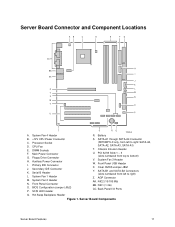
Secondary IDE Connector K. BIOS Configuration Jumper (J8J2) P. SATA-A1 through SATA-A4 Connector (S875WP1LX only, from left to right: SATA-A4, SATA-A2, SATA-A3, SATA-A1) T. System Fan 3 Header W. Hot Swap Backplane Header Figure 1. System ... N. Clear CMOS Jumper J8G1 Y. NIC1 (1 Gb) CC. Processor Socket D. DIMM Sockets F. Floppy Drive Connector H. Serial B Header L. Front Panel USB Header X. SATA-B1 and SATA-B2 Connectors (slots numbered from left to bottom) V. Server Board Connector and Component Locations AB C D E FG CC H BB I . Auxiliary Power Connector I...
Secondary IDE Connector K. BIOS Configuration Jumper (J8J2) P. SATA-A1 through SATA-A4 Connector (S875WP1LX only, from left to right: SATA-A4, SATA-A2, SATA-A3, SATA-A1) T. System Fan 3 Header W. Hot Swap Backplane Header Figure 1. System ... N. Clear CMOS Jumper J8G1 Y. NIC1 (1 Gb) CC. Processor Socket D. DIMM Sockets F. Floppy Drive Connector H. Serial B Header L. Front Panel USB Header X. SATA-B1 and SATA-B2 Connectors (slots numbered from left to bottom) V. Server Board Connector and Component Locations AB C D E FG CC H BB I . Auxiliary Power Connector I...
Product Guide
Page 14
.../support/motherboards/server/S875WP1-E Intel 875P Chipset The Intel 875P chipset consists of the BIOS. Check the Intel Customer Support website for ACPI Rev 2.0 compliant power management. • AGP 2.0 slot, also known as AGP 8x 14 Intel Server Board S875WP1-E Product Guide The MCH controls the Intel 82547EI from the CSA interface. Mixed mode DDR DS-DIMMs (x8 and...
.../support/motherboards/server/S875WP1-E Intel 875P Chipset The Intel 875P chipset consists of the BIOS. Check the Intel Customer Support website for ACPI Rev 2.0 compliant power management. • AGP 2.0 slot, also known as AGP 8x 14 Intel Server Board S875WP1-E Product Guide The MCH controls the Intel 82547EI from the CSA interface. Mixed mode DDR DS-DIMMs (x8 and...
Product Guide
Page 15
...Hub (ICH5-R) The Intel 82801EB ICH5-R has these features: • Upstream Hub Interface to the MCH • Integrated IDE controller (supports two Ultra ATA-100/66 mode, Ultra DMA 33 mode, and PIO mode). • Integrated SATA controller supports two SATA devices with transfer speeds ... and updating of platform information Video The server board S875WP1-E contains two separate, mutually exclusive graphics subsystems. You can use either the AGP connector or the ATI Rage XL video controller. Intel 82802AC Firmware Hub (FWH) The Intel 82802AC Firmware Hub (FWH) includes an 8 megabit symmetrical...
...Hub (ICH5-R) The Intel 82801EB ICH5-R has these features: • Upstream Hub Interface to the MCH • Integrated IDE controller (supports two Ultra ATA-100/66 mode, Ultra DMA 33 mode, and PIO mode). • Integrated SATA controller supports two SATA devices with transfer speeds ... and updating of platform information Video The server board S875WP1-E contains two separate, mutually exclusive graphics subsystems. You can use either the AGP connector or the ATI Rage XL video controller. Intel 82802AC Firmware Hub (FWH) The Intel 82802AC Firmware Hub (FWH) includes an 8 megabit symmetrical...
Product Guide
Page 16
... 100 Hz vertical refresh rate. Supported 32 bpp Supported Supported Supported Supported Supported continued 16 Intel Server Board S875WP1-E Product Guide AGP is independent of the PCI slots. ATA Rage XL Video Controller The S875WP1-E server board provides an ATI Rage XL PCI graphics accelerator, along with legacy 3.3 ...4X, or 8X AGP protocol • 1.5 V add-in 8/16/24/32 bpp modes under 3D. The AGP connector on -board video through the BIOS Setup menu or when a plug-in video card is installed in a 272-pin PBGA. Table 3. Video Modes The Rage XL chip supports all standard...
... 100 Hz vertical refresh rate. Supported 32 bpp Supported Supported Supported Supported Supported continued 16 Intel Server Board S875WP1-E Product Guide AGP is independent of the PCI slots. ATA Rage XL Video Controller The S875WP1-E server board provides an ATI Rage XL PCI graphics accelerator, along with legacy 3.3 ...4X, or 8X AGP protocol • 1.5 V add-in 8/16/24/32 bpp modes under 3D. The AGP connector on -board video through the BIOS Setup menu or when a plug-in video card is installed in a 272-pin PBGA. Table 3. Video Modes The Rage XL chip supports all standard...
Product Guide
Page 17
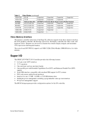
...,100 Supported Supported Supported Supported 1280x1024 43,60,70,72 Supported Supported - - 1600x1200 60,66,76,85 Supported - - - Server Board Features 17 The server board S875WP1-E supports an 8 MB (512Kx32bitx4 Banks) SDRAM device for the I /O Controller provides the following features: • Low pin count (LPC) interface • 3.3 V ...44 MB, or 2.88 MB diskette drive • Intelligent power management, including a programmable wake up event interface • PCI power management support The BIOS Setup program provides configuration options for video memory. Table 3.
...,100 Supported Supported Supported Supported 1280x1024 43,60,70,72 Supported Supported - - 1600x1200 60,66,76,85 Supported - - - Server Board Features 17 The server board S875WP1-E supports an 8 MB (512Kx32bitx4 Banks) SDRAM device for the I /O Controller provides the following features: • Low pin count (LPC) interface • 3.3 V ...44 MB, or 2.88 MB diskette drive • Intelligent power management, including a programmable wake up event interface • PCI power management support The BIOS Setup program provides configuration options for video memory. Table 3.
Product Guide
Page 18
..., provides the keyboard and mouse control functions, and supports password protection for an option Serial B port. Serial Port The server board S875WP1-E has one serial port connector and one diskette drive that , like a self-healing fuse, reestablishes the connection after an overcurrent condition... port header. The serial port A connector is connected or disconnected. A DH10 10-pin serial header is supported in the BIOS Setup program. 18 Intel Server Board S875WP1-E Product Guide A power-on the back panel. The +5 V lines to these connectors are located on /reset password can...
..., provides the keyboard and mouse control functions, and supports password protection for an option Serial B port. Serial Port The server board S875WP1-E has one serial port connector and one diskette drive that , like a self-healing fuse, reestablishes the connection after an overcurrent condition... port header. The serial port A connector is connected or disconnected. A DH10 10-pin serial header is supported in the BIOS Setup program. 18 Intel Server Board S875WP1-E Product Guide A power-on the back panel. The +5 V lines to these connectors are located on /reset password can...
Product Guide
Page 19
...initialization. the other two are routed to USB 1.1 operation. Four ports are accessible via the ICH5. Disabling High-Speed USB in BIOS reverts all USB 2.0 ports to the back panel. Computer systems that meets the requirements for full-speed devices. By default, Legacy... USB support is attached to Enabled. The S875WP1-E server board fully supports UHCI and uses UHCI-compatible software drivers. ✏ NOTE Computer systems that have an unshielded cable attached to...
...initialization. the other two are routed to USB 1.1 operation. Four ports are accessible via the ICH5. Disabling High-Speed USB in BIOS reverts all USB 2.0 ports to the back panel. Computer systems that meets the requirements for full-speed devices. By default, Legacy... USB support is attached to Enabled. The S875WP1-E server board fully supports UHCI and uses UHCI-compatible software drivers. ✏ NOTE Computer systems that have an unshielded cable attached to...
Product Guide
Page 20
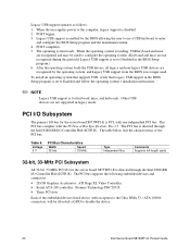
... Each of the PCI bus. Legacy USB support is enabled by the operating system, and Legacy USB support from the BIOS is set to disable the device. 20 Intel Server Board S875WP1-E Product Guide Legacy USB support operates as follows: 1. The operating system loads. While the operating system is directed through... full-length cards 32-bit, 33-MHz PCI Subsystem All 32-bit, 33-MHz PCI I/O for the server board S875WP1-E is loading, USB keyboard and mice are not supported in the BIOS Setup program.) 6. The PCI bus is disabled. 2. When the user applies power to the Ultra DMA 33 / ...
... Each of the PCI bus. Legacy USB support is enabled by the operating system, and Legacy USB support from the BIOS is set to disable the device. 20 Intel Server Board S875WP1-E Product Guide Legacy USB support operates as follows: 1. The operating system loads. While the operating system is directed through... full-length cards 32-bit, 33-MHz PCI Subsystem All 32-bit, 33-MHz PCI I/O for the server board S875WP1-E is loading, USB keyboard and mice are not supported in the BIOS Setup program.) 6. The PCI bus is disabled. 2. When the user applies power to the Ultra DMA 33 / ...
Product Guide
Page 22
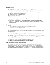
The BIOS supports Logical Block Addressing (LBA) and Extended Cylinder Head Sector (ECHS) translation modes. For proper operation, this connector should be wired to , both the add-in SCSI controller and the IDE controller. 22 Intel Server Board S875WP1-E Product Guide floppy disk drive) • ARMD-HDD (... devices (such as the onboard IDE controller. The LED indicates when data is a faster timing and requires a specialized cable to the BIOS. The interface handles the exchange of the following: • ARMD-FDD (ATAPI removable media device - The drive reports the transfer rate...
The BIOS supports Logical Block Addressing (LBA) and Extended Cylinder Head Sector (ECHS) translation modes. For proper operation, this connector should be wired to , both the add-in SCSI controller and the IDE controller. 22 Intel Server Board S875WP1-E Product Guide floppy disk drive) • ARMD-HDD (... devices (such as the onboard IDE controller. The LED indicates when data is a faster timing and requires a specialized cable to the BIOS. The interface handles the exchange of the following: • ARMD-FDD (ATAPI removable media device - The drive reports the transfer rate...
Product Guide
Page 23
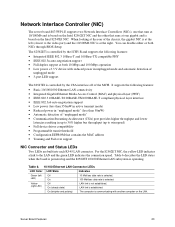
... disable either or both 10 Mbps and 100 Mbps operation • Low power +3.3 V device with another computer on the Intel 82547EI NIC. The 82562ET is controlled by the CSA interface off of the MCH. Yellow (right LED) Off On (steady... the connection speed. Network Interface Controller (NIC) The server board S875WP1-E supports two Network Interface Controllers (NICs), one that runs at 10/100Mb and is based on the Intel 82562ET NIC and the other that contains the MAC address •... • IEEE 802.3u auto-negotiation support • Full duplex support at both NICs through BIOS Setup.
... disable either or both 10 Mbps and 100 Mbps operation • Low power +3.3 V device with another computer on the Intel 82547EI NIC. The 82562ET is controlled by the CSA interface off of the MCH. Yellow (right LED) Off On (steady... the connection speed. Network Interface Controller (NIC) The server board S875WP1-E supports two Network Interface Controllers (NICs), one that runs at 10/100Mb and is based on the Intel 82562ET NIC and the other that contains the MAC address •... • IEEE 802.3u auto-negotiation support • Full duplex support at both NICs through BIOS Setup.
Product Guide
Page 26
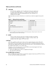
...the power supply. The LAN subsystem PCI bus network adapter monitors network traffic at the Media Independent Interface. Depending on the LAN implementation, the S875WP1-E server board supports LAN wake capabilities with Wake on PME enabled in the following ways: • The PCI bus PME# signal for ...-up Devices and Events These devices/events can wake the computer from an ACPI S1, S3, S4, or S5 state (with ACPI in BIOS). 26 Intel Server Board S875WP1-E Product Guide Upon detecting a Magic Packet* frame, the LAN subsystem asserts a wake-up signal that provides full ACPI support.
...the power supply. The LAN subsystem PCI bus network adapter monitors network traffic at the Media Independent Interface. Depending on the LAN implementation, the S875WP1-E server board supports LAN wake capabilities with Wake on PME enabled in the following ways: • The PCI bus PME# signal for ...-up Devices and Events These devices/events can wake the computer from an ACPI S1, S3, S4, or S5 state (with ACPI in BIOS). 26 Intel Server Board S875WP1-E Product Guide Upon detecting a Magic Packet* frame, the LAN subsystem asserts a wake-up signal that provides full ACPI support.

Product Guide
Page 28
Plug the power cables into the pin 1 end of the Hardware Management ASIC (Fans 1, 2, and 4 only). 28 Intel Server Board S875WP1-E Product Guide With soft-off enabled, if power to the computer is interrupted by a power outage or a disconnected power cord, when power resumes, the .... Power Connector When used with an ATX12V or EPS12V compliant power supply that supports remote power on/off, the S875WP1-E server board can be set using the After Power Failure feature in the BIOS Setup program's Boot menu. ✏ NOTE A standard ATX 20 pin power connector and standard ATX 12V 4-pin ...
Plug the power cables into the pin 1 end of the Hardware Management ASIC (Fans 1, 2, and 4 only). 28 Intel Server Board S875WP1-E Product Guide With soft-off enabled, if power to the computer is interrupted by a power outage or a disconnected power cord, when power resumes, the .... Power Connector When used with an ATX12V or EPS12V compliant power supply that supports remote power on/off, the S875WP1-E server board can be set using the After Power Failure feature in the BIOS Setup program's Boot menu. ✏ NOTE A standard ATX 20 pin power connector and standard ATX 12V 4-pin ...

Product Guide
Page 30
...can be configured through the BIOS Setup screens. ✏ NOTE Chassis intrusion detection may be monitored with the Wired for download at: http://www.support.intel.com/support/motherboards/server/S875WP1-E Chassis Intrusion and Detection The server board S875WP1-E supports a chassis security...party software. • Chassis intrusion detection The server board S875WP1-E has an integrated Hardware Management ASIC that alerts a system administrator if a hardware problem occurs on an Intel Server Board S875WP1-E based system. Hardware Management and Monitoring The Hardware Management ...
...can be configured through the BIOS Setup screens. ✏ NOTE Chassis intrusion detection may be monitored with the Wired for download at: http://www.support.intel.com/support/motherboards/server/S875WP1-E Chassis Intrusion and Detection The server board S875WP1-E supports a chassis security...party software. • Chassis intrusion detection The server board S875WP1-E has an integrated Hardware Management ASIC that alerts a system administrator if a hardware problem occurs on an Intel Server Board S875WP1-E based system. Hardware Management and Monitoring The Hardware Management ...

Product Guide
Page 31
... of Setup gives the user restricted access to Setup. • If both passwords are then available for a password. Password Security The BIOS includes security features that restrict whether the BIOS Setup program can be set for the Setup menu and for booting the server, with the following restrictions: • The supervisor password...
... of Setup gives the user restricted access to Setup. • If both passwords are then available for a password. Password Security The BIOS includes security features that restrict whether the BIOS Setup program can be set for the Setup menu and for booting the server, with the following restrictions: • The supervisor password...
Product Guide
Page 32
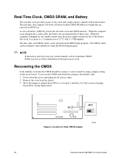
...CMOS and return the settings to cover pins 2 and three. J8G1 12 3 Figure 5. Recovering the CMOS In the unlikely event that are reserved for BIOS use. The real-time clock supports 256 bytes of battery-backed CMOS SRAM in , the standby current from the chassis. 3. The CMOS values can...server board. A coin-cell battery (CR2032) powers the real-time clock and CMOS memory. For the location of Clear CMOS Jumper TP00200 32 Intel Server Board S875WP1-E Product Guide When the computer is not plugged into CMOS RAM at 25 ºC with alarm features. Move the jumper at jumper block ...
...CMOS and return the settings to cover pins 2 and three. J8G1 12 3 Figure 5. Recovering the CMOS In the unlikely event that are reserved for BIOS use. The real-time clock supports 256 bytes of battery-backed CMOS SRAM in , the standby current from the chassis. 3. The CMOS values can...server board. A coin-cell battery (CR2032) powers the real-time clock and CMOS memory. For the location of Clear CMOS Jumper TP00200 32 Intel Server Board S875WP1-E Product Guide When the computer is not plugged into CMOS RAM at 25 ºC with alarm features. Move the jumper at jumper block ...
Product Guide
Page 33
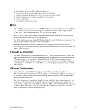
...BIOS The S875WP1-E server board uses an Intel/AMI BIOS that it covers pins 1 and 2. 7. The BIOS displays a message during POST identifying the type of the high capacities typically available today, hard drives are considered to be onboard or add-in the BIOS and reports if the two match. PCI Auto Configuration The BIOS... take advantage of BIOS and a revision code. The initial production BIOS is powered-up to configure the system. The S875WP1-E server board supports system BIOS shadowing, allowing the BIOS to optimize capacity and performance. When the S875WP1-E server board's ...
...BIOS The S875WP1-E server board uses an Intel/AMI BIOS that it covers pins 1 and 2. 7. The BIOS displays a message during POST identifying the type of the high capacities typically available today, hard drives are considered to be onboard or add-in the BIOS and reports if the two match. PCI Auto Configuration The BIOS... take advantage of BIOS and a revision code. The initial production BIOS is powered-up to configure the system. The S875WP1-E server board supports system BIOS shadowing, allowing the BIOS to optimize capacity and performance. When the S875WP1-E server board's ...


