User Guide
Page 17
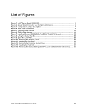
... 18 Figure 8. Installing the Heat Sink 22 Figure 14. Removing the Shipping Cover 21 Figure 11. Replacing the Backup Battery (S5000VSASATA/S5000VSASATAR shown) ....... 25 Intel® Server Board S5000VSA User's Guide xvii CMOS Clear Jumper 16 Figure 7. Installing the Processor 21 Figure 12. Server Board Connector and Component Locations 6 Figure... 15 Figure 6. Open the Load Plate 20 Figure 10. Removing the Protective Socket Cover 21 Figure 13. Lifting the Socket Handle 20 Figure 9. Intel® Server Board S5000VSA 1 Figure 2. List of Figures Figure 1.
... 18 Figure 8. Installing the Heat Sink 22 Figure 14. Removing the Shipping Cover 21 Figure 11. Replacing the Backup Battery (S5000VSASATA/S5000VSASATAR shown) ....... 25 Intel® Server Board S5000VSA User's Guide xvii CMOS Clear Jumper 16 Figure 7. Installing the Processor 21 Figure 12. Server Board Connector and Component Locations 6 Figure... 15 Figure 6. Open the Load Plate 20 Figure 10. Removing the Protective Socket Cover 21 Figure 13. Lifting the Socket Handle 20 Figure 9. Intel® Server Board S5000VSA 1 Figure 2. List of Figures Figure 1.
User Guide
Page 20
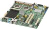
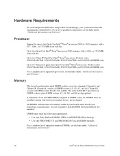
...-X* connector • One 64-bit/100MHz PCI-X* connector • Two x4 PCI Express* connectors 2 Intel® Server Board S5000VSA User's Guide Up to two Quad-Core Intel® Xeon® processors 5300 sequence with a 1066- Product codes S5000VSASATAR, S5000VSASASR, S5000VSASCSIR, and S5000VSA4DIMMR only. • Entry SATA sku: four DIMM sockets supporting stacked DDR2...
...-X* connector • One 64-bit/100MHz PCI-X* connector • Two x4 PCI Express* connectors 2 Intel® Server Board S5000VSA User's Guide Up to two Quad-Core Intel® Xeon® processors 5300 sequence with a 1066- Product codes S5000VSASATAR, S5000VSASASR, S5000VSASCSIR, and S5000VSA4DIMMR only. • Entry SATA sku: four DIMM sockets supporting stacked DDR2...
User Guide
Page 21
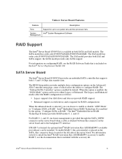
... model provides only SATA support. For information on the server board when a cable is attached between this option is desired, the optional Intel® RAID Activation Key AXXRAKSW5 (available post-release) can be installed. The "Onboard SATA Controller" option is provided through the SATA_SGPIO ...to enable or disable "AHCI Mode" or "Configure SATA as RAID." The SATA model has order code S5000VSASATA/S5000VSASATAR. When this connector on how to install the Intel® RAID Activation Key AXXRAKSW5 accessory to enable RAID 5, see the RAID Software Guide that is included with...
... model provides only SATA support. For information on the server board when a cable is attached between this option is desired, the optional Intel® RAID Activation Key AXXRAKSW5 (available post-release) can be installed. The "Onboard SATA Controller" option is provided through the SATA_SGPIO ...to enable or disable "AHCI Mode" or "Configure SATA as RAID." The SATA model has order code S5000VSASATA/S5000VSASATAR. When this connector on how to install the Intel® RAID Activation Key AXXRAKSW5 accessory to enable RAID 5, see the RAID Software Guide that is included with...
User Guide
Page 28
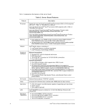
...All DIMMs with a 1066- For a list of supported memory DIMMs, see the links under "Additional Information and Software." 10 Intel® Server Board S5000VSA User's Guide Channel A consists of supported processors, see the links under "Additional Information and Software." For...bus. or 1333-MHz front side bus. Product codes S5000VSASATAR, S5000VSASASR, S5000VSASCSIR, and S5000VSA4DIMMR only. Product codes S5000VSASATAR, S5000VSASASR, S5000VSASCSIR, and S5000VSA4DIMMR only. Channel B consists of one or two Dual-Core Intel® Xeon® processors 5000 or 5100 sequence ...
...All DIMMs with a 1066- For a list of supported memory DIMMs, see the links under "Additional Information and Software." 10 Intel® Server Board S5000VSA User's Guide Channel A consists of supported processors, see the links under "Additional Information and Software." For...bus. or 1333-MHz front side bus. Product codes S5000VSASATAR, S5000VSASASR, S5000VSASCSIR, and S5000VSA4DIMMR only. Product codes S5000VSASATAR, S5000VSASASR, S5000VSASCSIR, and S5000VSA4DIMMR only. Channel B consists of one or two Dual-Core Intel® Xeon® processors 5000 or 5100 sequence ...

User Guide
Page 29
...can be connected to the standard IDE connector located near the front left side of the server board purchased. • The Intel® Server Board S5000VSASATA/S5000VSASATAR provides six SATA ports and one IDE connection. Your supply must provide a minimum of 3A of 550 Watts is required. ...The six SATA ports are near the SATA ports. • The Intel® Server Board S5000VSASAS/S5000VSASASR provides four SAS ports and...
...can be connected to the standard IDE connector located near the front left side of the server board purchased. • The Intel® Server Board S5000VSASATA/S5000VSASATAR provides six SATA ports and one IDE connection. Your supply must provide a minimum of 3A of 550 Watts is required. ...The six SATA ports are near the SATA ports. • The Intel® Server Board S5000VSASAS/S5000VSASASR provides four SAS ports and...
User Guide
Page 38
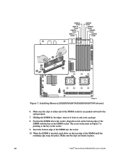
... the bottom edge of the DIMM until the retaining clips snap into the socket. 10. Installing Memory (S5000VSASATA/S5000VSASATAR shown) 6. Make sure the clips are pushed outward to the key in place. 20 "Intel® Server Board S5000VSA User's Guide" DIMM A4 Socket DIMM A3 Socket DIMM A2 Socket DIMM A1 Socket...
... the bottom edge of the DIMM until the retaining clips snap into the socket. 10. Installing Memory (S5000VSASATA/S5000VSASATAR shown) 6. Make sure the clips are pushed outward to the key in place. 20 "Intel® Server Board S5000VSA User's Guide" DIMM A4 Socket DIMM A3 Socket DIMM A2 Socket DIMM A1 Socket...

User Guide
Page 45
... of the battery according to observe the correct polarity, insert it in "Safety Information". 2. Remove the battery from the server. 4. Replacing the Backup Battery (S5000VSASATA/ S5000VSASATAR shown) 7. Remove the new lithium battery from its socket. Run Setup to restore the configuration settings to lift the battery. 6. Remove the server's cover and.... 9. Turn off the server. 3. See the documentation that came with your server chassis for instructions on the screwdriver to the RTC. Close the chassis. 10. "Intel® Server Board S5000VSA User's Guide" 27
... of the battery according to observe the correct polarity, insert it in "Safety Information". 2. Remove the battery from the server. 4. Replacing the Backup Battery (S5000VSASATA/ S5000VSASATAR shown) 7. Remove the new lithium battery from its socket. Run Setup to restore the configuration settings to lift the battery. 6. Remove the server's cover and.... 9. Turn off the server. 3. See the documentation that came with your server chassis for instructions on the screwdriver to the RTC. Close the chassis. 10. "Intel® Server Board S5000VSA User's Guide" 27


