User Guide
Page 7
...replacing components such as the memory, processor, and the CMOS battery. Unless specified, features apply to the Technical Product Specification. Manual Organization Chapter 1 provides a brief overview of the server board. This includes how to navigate through.... In this server board. See "Additional Information and Software" on using the Intel® Server Board S5000PSL. This manual is available in this manual, see http://support.intel.com/support/motherboards/server/S5000PSL/. Chapter 3 provides instructions on the Intel® Server Board S5000PSL. Note: Unless...
...replacing components such as the memory, processor, and the CMOS battery. Unless specified, features apply to the Technical Product Specification. Manual Organization Chapter 1 provides a brief overview of the server board. This includes how to navigate through.... In this server board. See "Additional Information and Software" on using the Intel® Server Board S5000PSL. This manual is available in this manual, see http://support.intel.com/support/motherboards/server/S5000PSL/. Chapter 3 provides instructions on the Intel® Server Board S5000PSL. Note: Unless...
User Guide
Page 8
..., memory, processors, and third-party hardware have been tested and can be used with this Document or Software Intel® Server Board S5000PSL Technical Product Specification and the Intel® S5000 Series Chipsets Server Board Family Datasheet. Product Accessories This server board is available under Other Resources at the right side of the screen at http://support.intel.com/support/motherboards/server/S5000PSL/ Table...
..., memory, processors, and third-party hardware have been tested and can be used with this Document or Software Intel® Server Board S5000PSL Technical Product Specification and the Intel® S5000 Series Chipsets Server Board Family Datasheet. Product Accessories This server board is available under Other Resources at the right side of the screen at http://support.intel.com/support/motherboards/server/S5000PSL/ Table...

User Guide
Page 9
...See the section on the web page titled Installation & Use Intel System Management Software. Diagnostics. See also the Intel® Server Deployment Toolkit 2.0 CD that have been tested with your Intel® server Drivers Firmware and BIOS updates, or BIOS recovery files Diagnostics ...make sure your system falls within the allowed power budget Software to manage your server board. See the section on the web page titled Software & Drivers. Intel® Server Board S5000PSL ix Supported Processors. See the section on the web page titled Compatibility. Firmware Updates. Reference ...
...See the section on the web page titled Installation & Use Intel System Management Software. Diagnostics. See also the Intel® Server Deployment Toolkit 2.0 CD that have been tested with your Intel® server Drivers Firmware and BIOS updates, or BIOS recovery files Diagnostics ...make sure your system falls within the allowed power budget Software to manage your server board. See the section on the web page titled Software & Drivers. Intel® Server Board S5000PSL ix Supported Processors. See the section on the web page titled Compatibility. Firmware Updates. Reference ...

User Guide
Page 11
... Manual ...vii Manual Organization ...vii Product Accessories ...viii Additional Information and Software viii Chapter 1: Server Board Features 1 Connector and Header Locations 5 Configuration Jumpers ...7 Intel® Light-Guided Diagnostics 9 Back Panel Features ...12 RAID Support ...13 SATA Server Board ...13 SAS Server Board ...14 ROMB Server Board ...15 Hardware Requirements ...16 Processor ...16 Memory ...16 Power Supply ...18 Optional Hardware ...19...
... Manual ...vii Manual Organization ...vii Product Accessories ...viii Additional Information and Software viii Chapter 1: Server Board Features 1 Connector and Header Locations 5 Configuration Jumpers ...7 Intel® Light-Guided Diagnostics 9 Back Panel Features ...12 RAID Support ...13 SATA Server Board ...13 SAS Server Board ...14 ROMB Server Board ...15 Hardware Requirements ...16 Processor ...16 Memory ...16 Power Supply ...18 Optional Hardware ...19...

User Guide
Page 12
... Removing Memory 29 Installing FBDIMMs ...29 Removing FBDIMMs 32 Installing or Replacing the Processor 32 Installing the Processor 33 Installing the Heatsink(s 37 Removing a Processor 40 Replacing the CMOS Battery 43 Appendix A: Troubleshooting 45 System Boot Quiet Time... CD-ROM Drive or DVD-ROM Drive Activity Light Does Not Light 50 Cannot Connect to a Server 51 Problems with Network 51 System Boots when Installing PCI Card 52 Problems with Newly Installed Application ... Regulatory and Compliance Information 57 Product Regulatory Compliance 57 xii Intel® Server Board S5000PSL
... Removing Memory 29 Installing FBDIMMs ...29 Removing FBDIMMs 32 Installing or Replacing the Processor 32 Installing the Processor 33 Installing the Heatsink(s 37 Removing a Processor 40 Replacing the CMOS Battery 43 Appendix A: Troubleshooting 45 System Boot Quiet Time... CD-ROM Drive or DVD-ROM Drive Activity Light Does Not Light 50 Cannot Connect to a Server 51 Problems with Network 51 System Boots when Installing PCI Card 52 Problems with Newly Installed Application ... Regulatory and Compliance Information 57 Product Regulatory Compliance 57 xii Intel® Server Board S5000PSL

User Guide
Page 15
...36 Figure 15. Configuration Jumpers 8 Figure 4. DIMM Sockets...17 Figure 6. Setting Processor in the Clear CMOS Position 27 Figure 9. Locating and Removing the CMOS Battery 44 Intel® Server Board S5000PSL xv Opening Processor Socket Lever 35 Figure 13. Locating Active Heatsink Cable Connections 39 Figure 18. ...Load Plate 42 Figure 22. Installing Heatsink (passive heatsink shown 38 Figure 17. List of Figures Figure 1. Intel® Server Board S5000PSL 1 Figure 2. Server Board Connector and Component Locations 6 Figure 3. Locating DIMM Sockets 30 Figure 10.
...36 Figure 15. Configuration Jumpers 8 Figure 4. DIMM Sockets...17 Figure 6. Setting Processor in the Clear CMOS Position 27 Figure 9. Locating and Removing the CMOS Battery 44 Intel® Server Board S5000PSL xv Opening Processor Socket Lever 35 Figure 13. Locating Active Heatsink Cable Connections 39 Figure 18. ...Load Plate 42 Figure 22. Installing Heatsink (passive heatsink shown 38 Figure 17. List of Figures Figure 1. Intel® Server Board S5000PSL 1 Figure 2. Server Board Connector and Component Locations 6 Figure 3. Locating DIMM Sockets 30 Figure 10.

User Guide
Page 20
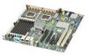
...PCI Express* x4 slots (product code S5000PSLSAS or S5000PSLSASR) • Two PCI Express x8 slots (product code S5000PSLSATA, S5000PSLSATAR, S5000XSLSATA, or S5000XSLSATAR) 2 Intel® Server Board S5000PSL Six expansion slots: • One PCI-X* 64-bit / 100-MHz slot • One PCI-X* 64-bit / 100- / 133-MHz slot ... Fan 4 are compatible with all fan headers. 4-pin fans should be used only with the 4-pin active heatsink fans. Server Board Features Feature Processor support System memory support Intel® 5000P Chipset Cooling Add-in card slots Description • Up to two Dual-Core...
...PCI Express* x4 slots (product code S5000PSLSAS or S5000PSLSASR) • Two PCI Express x8 slots (product code S5000PSLSATA, S5000PSLSATAR, S5000XSLSATA, or S5000XSLSATAR) 2 Intel® Server Board S5000PSL Six expansion slots: • One PCI-X* 64-bit / 100-MHz slot • One PCI-X* 64-bit / 100- / 133-MHz slot ... Fan 4 are compatible with all fan headers. 4-pin fans should be used only with the 4-pin active heatsink fans. Server Board Features Feature Processor support System memory support Intel® 5000P Chipset Cooling Add-in card slots Description • Up to two Dual-Core...

User Guide
Page 22
... and RAM are installed, hardware RAID support is available for Intel® System Management software • Intel® Light-Guided Diagnostics on field replaceable units 4 Intel® Server Board S5000PSL Feature RAID support Cooling fan support Management support Table 2. Product code S5000PSLROMB and S5000PSLROMBR: Intel® Integrated Server RAID provides four internal and four external SAS ports. Uses...
... and RAM are installed, hardware RAID support is available for Intel® System Management software • Intel® Light-Guided Diagnostics on field replaceable units 4 Intel® Server Board S5000PSL Feature RAID support Cooling fan support Management support Table 2. Product code S5000PSLROMB and S5000PSLROMBR: Intel® Integrated Server RAID provides four internal and four external SAS ports. Uses...

User Guide
Page 23
...133-MHz R. SATA 0 E. Processor 1 socket slot 2 GG. Hot-swap backplane A header D. Connector and Header Locations GI A B CDE F H J KL TT SS M N O RR QQ PP OO NN MM LL KK JJ II HH GG FF DD BB Z X V EE CC AA Y W P Q R S T U AF000247 A. Hot-swap backplane B on page 17) header B. SATA 1 Intel® Server Board S5000PSL 5 PCI Express x4... slot 4 (ROMB slot) U. Processor 2 socket HH.
...133-MHz R. SATA 0 E. Processor 1 socket slot 2 GG. Hot-swap backplane A header D. Connector and Header Locations GI A B CDE F H J KL TT SS M N O RR QQ PP OO NN MM LL KK JJ II HH GG FF DD BB Z X V EE CC AA Y W P Q R S T U AF000247 A. Hot-swap backplane B on page 17) header B. SATA 1 Intel® Server Board S5000PSL 5 PCI Express x4... slot 4 (ROMB slot) U. Processor 2 socket HH.

User Guide
Page 24
... connector Y. IDE connector DD. Serial B / emergency management port header TT. RMM connector (connector for Intel® Remote Management Module) K. System fan 2 header Z. Intel® Local Control Panel header KK. SATA 2 or SAS 0 (SAS 0 is available only on...on product codes S5000PSLSAS and S5000PSLSASR) OO. Server Board Connector and Component Locations 6 Intel® Server Board S5000PSL Front control panel header QQ. SATA 3 or SAS 1 (SAS 1 is available only on product codes S5000PSLSAS and S5000PSLSASR) MM. Processor power connector BB. USB header CC. Chassis...
... connector Y. IDE connector DD. Serial B / emergency management port header TT. RMM connector (connector for Intel® Remote Management Module) K. System fan 2 header Z. Intel® Local Control Panel header KK. SATA 2 or SAS 0 (SAS 0 is available only on...on product codes S5000PSLSAS and S5000PSLSASR) OO. Server Board Connector and Component Locations 6 Intel® Server Board S5000PSL Front control panel header QQ. SATA 3 or SAS 1 (SAS 1 is available only on product codes S5000PSLSAS and S5000PSLSASR) MM. Processor power connector BB. USB header CC. Chassis...

User Guide
Page 29
...LED indicates a fault has occurred with the processor installed in socket DIMM_C2. Replace the faulty FBDIMM. DIMM D1 fault LED P. Processor 1 fault LED T. Replace the faulty FBDIMM. Replace the faulty unit. DIMM C1 fault LED N. Intel® Server Board S5000PSL 11 DIMM D2 fault LED Q. +5-volt ...standby LED R. This LED indicates a fault has occurred with fan that use an active heatsink. Replace the faulty processor. Replace the faulty unit. This LED indicates a...
...LED indicates a fault has occurred with the processor installed in socket DIMM_C2. Replace the faulty FBDIMM. DIMM D1 fault LED P. Processor 1 fault LED T. Replace the faulty FBDIMM. Replace the faulty unit. DIMM C1 fault LED N. Intel® Server Board S5000PSL 11 DIMM D2 fault LED Q. +5-volt ...standby LED R. This LED indicates a fault has occurred with fan that use an active heatsink. Replace the faulty processor. Replace the faulty unit. This LED indicates a...
User Guide
Page 34
... and S5000XSLSATAR only) • One or two 45 nm 2P Dual-Core Intel®Xeon® processors (Product codes S5000PSLSATAR, S5000PSLSASR, S5000PSLROMBR, and S5000XSLSATAR only) For a list of supported processors, see the links under "Additional Information and Software". Each branch contains two ..." on page viii. Memory The Intel® Server Board S5000PSL provides eight DIMM sockets in two branches. For a list of DIMM sockets D1 and D2 16 Intel® Server Board S5000PSL Hardware Requirements To avoid integration difficulties and possible board damage, your system must meet the...
... and S5000XSLSATAR only) • One or two 45 nm 2P Dual-Core Intel®Xeon® processors (Product codes S5000PSLSATAR, S5000PSLSASR, S5000PSLROMBR, and S5000XSLSATAR only) For a list of supported processors, see the links under "Additional Information and Software". Each branch contains two ..." on page viii. Memory The Intel® Server Board S5000PSL provides eight DIMM sockets in two branches. For a list of DIMM sockets D1 and D2 16 Intel® Server Board S5000PSL Hardware Requirements To avoid integration difficulties and possible board damage, your system must meet the...

User Guide
Page 50
... components necessary to dissipate the static charge while handling the processor. (2) Avoid moving around unnecessarily. 32 Intel® Server Board S5000PSL Push the clips at each end of electrostatic discharge (ESD) damage to the server. Turn off the server. 3. Turn off all peripheral devices connected to the processor by the edges, lift it from the socket. Caution: ESD...
... components necessary to dissipate the static charge while handling the processor. (2) Avoid moving around unnecessarily. 32 Intel® Server Board S5000PSL Push the clips at each end of electrostatic discharge (ESD) damage to the server. Turn off the server. 3. Turn off all peripheral devices connected to the processor by the edges, lift it from the socket. Caution: ESD...

User Guide
Page 51
... instructions on page iii. 2. Installing the Processor Notes: • Do not touch the contacts on either the processor or the processor socket. • Do not force the processor socket into place. When correctly aligned, the socket will easily drop into place. Remove the chassis cover. Disconnect the AC power cord from the server. 4. Intel® Server Board S5000PSL 33
... instructions on page iii. 2. Installing the Processor Notes: • Do not touch the contacts on either the processor or the processor socket. • Do not force the processor socket into place. When correctly aligned, the socket will easily drop into place. Remove the chassis cover. Disconnect the AC power cord from the server. 4. Intel® Server Board S5000PSL 33

User Guide
Page 52
While holding the lever down on removing chassis components. 7. CPU_1 Figure 11. Fully open the lever. Disconnect and remove any components necessary to the processor socket. Push down , pull it towards the center of the board to disengage the lever from the hook. Locating Processor Sockets 6. See Figure 12. 34 Intel® Server Board S5000PSL Processor Socket Callout Processor Socket CPU_2 B. See the documentation that came with your chassis for instructions on the lever attached to access the processor sockets. A B AF000419 Callout A.
While holding the lever down on removing chassis components. 7. CPU_1 Figure 11. Fully open the lever. Disconnect and remove any components necessary to the processor socket. Push down , pull it towards the center of the board to disengage the lever from the hook. Locating Processor Sockets 6. See Figure 12. 34 Intel® Server Board S5000PSL Processor Socket Callout Processor Socket CPU_2 B. See the documentation that came with your chassis for instructions on the lever attached to access the processor sockets. A B AF000419 Callout A.

User Guide
Page 53
Fully open the load plate. Opening Load Plate AF000096 Intel® Server Board S5000PSL 35 Push down on the rear tab of the load plate to swing the front of the load plate up slightly. Opening Processor Socket Lever 8. Figure 13. See Figure 13. AF000095 Figure 12.
Fully open the load plate. Opening Load Plate AF000096 Intel® Server Board S5000PSL 35 Push down on the rear tab of the load plate to swing the front of the load plate up slightly. Opening Processor Socket Lever 8. Figure 13. See Figure 13. AF000095 Figure 12.

User Guide
Page 54
... the heatsink(s). See Figure 15. See "Installing the Heatsink(s)" on the socket lever while pushing it toward the center of the processor socket to engage it for instructions. 36 Intel® Server Board S5000PSL AF000097 Figure 14. Close the load plate. 13. Removing Protective Cover from the box and remove the protective shipping cover. 11...
... the heatsink(s). See Figure 15. See "Installing the Heatsink(s)" on the socket lever while pushing it toward the center of the processor socket to engage it for instructions. 36 Intel® Server Board S5000PSL AF000097 Figure 14. Close the load plate. 13. Removing Protective Cover from the box and remove the protective shipping cover. 11...

User Guide
Page 55
... for Compatible Intel® Server Chassis Server Chassis Intel® Entry Server Chassis SC5299-E BRP Intel® Entry Server Chassis SC5299-E DP Intel® Entry Server Chassis SC5299-E WS Intel® Server Chassis SC5400 BRP Intel® Server Chassis SC5400 LX Intel® Server Chassis SC5400 Base Heatsink Requirement Active heatsink Active heatsink Active heatsink Passive heatsink Passive heatsink Passive heatsink Intel® Server Board S5000PSL 37 Each processor requires...
... for Compatible Intel® Server Chassis Server Chassis Intel® Entry Server Chassis SC5299-E BRP Intel® Entry Server Chassis SC5299-E DP Intel® Entry Server Chassis SC5299-E WS Intel® Server Chassis SC5400 BRP Intel® Server Chassis SC5400 LX Intel® Server Chassis SC5400 Base Heatsink Requirement Active heatsink Active heatsink Active heatsink Passive heatsink Passive heatsink Passive heatsink Intel® Server Board S5000PSL 37 Each processor requires...

User Guide
Page 56
... and equally tighten each captive screw until each is firmly tightened. Installing Heatsink (passive heatsink shown) 38 Intel® Server Board S5000PSL Install the processor. Set the heatsink over the processor, lining up the four captive screws with the four posts surrounding the processor. 3. Do not fully tighten one screw at a time. 2 4 3 1 FCrhoanst sis AF000098 Figure 16...
... and equally tighten each captive screw until each is firmly tightened. Installing Heatsink (passive heatsink shown) 38 Intel® Server Board S5000PSL Install the processor. Set the heatsink over the processor, lining up the four captive screws with the four posts surrounding the processor. 3. Do not fully tighten one screw at a time. 2 4 3 1 FCrhoanst sis AF000098 Figure 16...

User Guide
Page 57
... components. 7. CPU_2 B. Reinstall and reconnect any parts you removed or disconnected to the server board. See the documentation that came with your chassis for instructions on installing the cover. 5. Active heatsink only: Connect the heatsink cable to reach the processor sockets. Replace the chassis cover and reconnect the AC power cord. Intel® Server Board S5000PSL 39
... components. 7. CPU_2 B. Reinstall and reconnect any parts you removed or disconnected to the server board. See the documentation that came with your chassis for instructions on installing the cover. 5. Active heatsink only: Connect the heatsink cable to reach the processor sockets. Replace the chassis cover and reconnect the AC power cord. Intel® Server Board S5000PSL 39


