
User Guide
Page 15
... Clear CMOS Position 27 Figure 9. Removing Protective Cover from Socket 42 Figure 21. Locating and Removing the CMOS Battery 44 Intel® Server Board S5000PSL xv CMOS Clr Jumper in Clear Password Position 26 Figure 8. Locating Processor Sockets 34 Figure 12. List of Figures Figure 1. Intel® Server Board S5000PSL 1 Figure 2. Server Board Connector and Component Locations 6 Figure 3. Configuration Jumpers 8 Figure 4. Back...
... Clear CMOS Position 27 Figure 9. Removing Protective Cover from Socket 42 Figure 21. Locating and Removing the CMOS Battery 44 Intel® Server Board S5000PSL xv CMOS Clr Jumper in Clear Password Position 26 Figure 8. Locating Processor Sockets 34 Figure 12. List of Figures Figure 1. Intel® Server Board S5000PSL 1 Figure 2. Server Board Connector and Component Locations 6 Figure 3. Configuration Jumpers 8 Figure 4. Back...

User Guide
Page 20
...Product codes S5000PSLSATAR, S5000PSLSASR, S5000PSLROMBR, and S5000XSLSATAR only • Eight FBDIMM sockets (DDR2-533 and DDR2-667) supporting 32 GB maximum memory • Quad-channel memory architecture • Product codes S5000PSLSATA, S5000PSLSATAR, S5000PSLSAS, S5000PSLSASR, S5000PSLROMB, S5000PSLROMBR: Intel® 5000P Memory Controller Hub • Product code S5000XSLSATA, S5000XSLSATAR... slots (product code S5000PSLSAS or S5000PSLSASR) • Two PCI Express x8 slots (product code S5000PSLSATA, S5000PSLSATAR, S5000XSLSATA, or S5000XSLSATAR) 2 Intel® Server Board S5000PSL
...Product codes S5000PSLSATAR, S5000PSLSASR, S5000PSLROMBR, and S5000XSLSATAR only • Eight FBDIMM sockets (DDR2-533 and DDR2-667) supporting 32 GB maximum memory • Quad-channel memory architecture • Product codes S5000PSLSATA, S5000PSLSATAR, S5000PSLSAS, S5000PSLSASR, S5000PSLROMB, S5000PSLROMBR: Intel® 5000P Memory Controller Hub • Product code S5000XSLSATA, S5000XSLSATAR... slots (product code S5000PSLSAS or S5000PSLSASR) • Two PCI Express x8 slots (product code S5000PSLSATA, S5000PSLSATAR, S5000XSLSATA, or S5000XSLSATAR) 2 Intel® Server Board S5000PSL

User Guide
Page 23
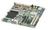
Hot-swap backplane B on page 17) header B. Processor 1 socket slot 2 GG. Hot-swap backplane A header D. SATA 1 Intel® Server Board S5000PSL 5 Processor 2 socket HH. SATA 0 E. Connector and Header Locations GI A B CDE F H J KL TT SS M N O RR QQ PP OO NN MM LL KK JJ II HH GG FF DD ...-X* 64-bit, 100-MHz slot 1 Q. PCI Express x4 slot 4 (ROMB slot) U. Enclosure management SAS SES2 (product codes S5000PSLSAS and S5000PSLSASR only) C. RMM NIC connector T. DIMM sockets (see Figure 5 FF.
Hot-swap backplane B on page 17) header B. Processor 1 socket slot 2 GG. Hot-swap backplane A header D. SATA 1 Intel® Server Board S5000PSL 5 Processor 2 socket HH. SATA 0 E. Connector and Header Locations GI A B CDE F H J KL TT SS M N O RR QQ PP OO NN MM LL KK JJ II HH GG FF DD ...-X* 64-bit, 100-MHz slot 1 Q. PCI Express x4 slot 4 (ROMB slot) U. Enclosure management SAS SES2 (product codes S5000PSLSAS and S5000PSLSASR only) C. RMM NIC connector T. DIMM sockets (see Figure 5 FF.

User Guide
Page 28
... status LED indicates whether a system is used to read these LEDs. This LED indicates a fault has occurred with the FBDIMM installed in socket DIMM_A2. Replace the faulty FBDIMM. 10 Intel® Server Board S5000PSL ID LED G. DIMM A2 fault LED K. POST LED. See the appendix of the Technical Product Specification for a description of how to...
... status LED indicates whether a system is used to read these LEDs. This LED indicates a fault has occurred with the FBDIMM installed in socket DIMM_A2. Replace the faulty FBDIMM. 10 Intel® Server Board S5000PSL ID LED G. DIMM A2 fault LED K. POST LED. See the appendix of the Technical Product Specification for a description of how to...

User Guide
Page 29
...applies only to be powered on . Replace the faulty unit. This LED indicates a fault has occurred with the FBDIMM installed in socket DIMM_B2. Intel® Server Board S5000PSL 11 LED DIMM B2 fault LED M. DIMM D2 fault LED Q. +5-volt standby LED R. Replace the faulty FBDIMM. This LED .... Replace the faulty unit. Processor 2 fault LED S. Replace the faulty FBDIMM. This LED applies only to server systems that is applied to be on in socket CPU_1 socket. Processor 1 fan fault LED Function This LED indicates a fault has occurred with fan that use an active heatsink...
...applies only to be powered on . Replace the faulty unit. This LED indicates a fault has occurred with the FBDIMM installed in socket DIMM_B2. Intel® Server Board S5000PSL 11 LED DIMM B2 fault LED M. DIMM D2 fault LED Q. +5-volt standby LED R. Replace the faulty FBDIMM. This LED .... Replace the faulty unit. Processor 2 fault LED S. Replace the faulty FBDIMM. This LED applies only to server systems that is applied to be on in socket CPU_1 socket. Processor 1 fan fault LED Function This LED indicates a fault has occurred with fan that use an active heatsink...
User Guide
Page 34
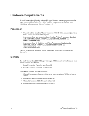
... supported processors, see the links under "Additional Information and Software". Hardware Requirements To avoid integration difficulties and possible board damage, your system must meet the requirements outlined below. Memory The Intel® Server Board S5000PSL provides eight DIMM sockets in two branches. Each branch contains two channels: • Branch 1 contains Channel A and Channel B • Branch 2 contains...
... supported processors, see the links under "Additional Information and Software". Hardware Requirements To avoid integration difficulties and possible board damage, your system must meet the requirements outlined below. Memory The Intel® Server Board S5000PSL provides eight DIMM sockets in two branches. Each branch contains two channels: • Branch 1 contains Channel A and Channel B • Branch 2 contains...

User Guide
Page 35
D. DIMM_A1 Branch 1, Channel A, F. DIMM_B1 Branch 1, Channel B, H. C. DIMM_B2 Branch 2, Channel C, DIMM_C1 Branch 2, Channel C, DIMM_C2 Branch 2, Channel D, DIMM_D1 Branch 2, Channel D, DIMM_D2 Figure 5. DIMM Sockets Intel® Server Board S5000PSL 17 See the following diagram to identify the DIMM sockets. D C B A E F G H AF000093 Callout A. DIMM Socket Callout DIMM Socket Branch 1, Channel A, E. DIMM_A2 Branch 1, Channel B, G. B.
D. DIMM_A1 Branch 1, Channel A, F. DIMM_B1 Branch 1, Channel B, H. C. DIMM_B2 Branch 2, Channel C, DIMM_C1 Branch 2, Channel C, DIMM_C2 Branch 2, Channel D, DIMM_D1 Branch 2, Channel D, DIMM_D2 Figure 5. DIMM Sockets Intel® Server Board S5000PSL 17 See the following diagram to identify the DIMM sockets. D C B A E F G H AF000093 Callout A. DIMM Socket Callout DIMM Socket Branch 1, Channel A, E. DIMM_A2 Branch 1, Channel B, G. B.

User Guide
Page 36
... and populated as follows: • DIMM_A1 and DIMM_B1: Populate these FBDIMMs in sockets A1, B1, C1, and D1. • The minimum memory population for any reason, the server will run in single-channel mode under "Additional Information and Software" on adjacent ...be identical. For a complete list of 5-volt standby current or the server will run in DIMM socket DIMM_A1. This FBDIMM must meet the population requirements are to be installed, they need to manufacturing, speed, timing, and organization. The server will not boot. 18 Intel® Server Board S5000PSL
... and populated as follows: • DIMM_A1 and DIMM_B1: Populate these FBDIMMs in sockets A1, B1, C1, and D1. • The minimum memory population for any reason, the server will run in single-channel mode under "Additional Information and Software" on adjacent ...be identical. For a complete list of 5-volt standby current or the server will run in DIMM socket DIMM_A1. This FBDIMM must meet the population requirements are to be installed, they need to manufacturing, speed, timing, and organization. The server will not boot. 18 Intel® Server Board S5000PSL

User Guide
Page 47
...FBDIMMs displays DIMM_A1, DIMM_A2, DIMM_B1, DIMM_B2, DIMM_C1, DIMM_C2, DIMM_D1, and DIMM_D2, starting from the server. 4. Observe the safety and ESD precautions in "Safety Information" on the board for a discussion of tested FBDIMMs. Installing FBDIMMs To install FBDIMMs, follow these steps: 1. Turn ...memory requirements and options. Remove the chassis cover. DIMM_A1 is the socket closest to the "Safety Information" on page iii. 3 Hardware Installations and Upgrades Before You Begin Before working with your server product, pay close attention to the MCH. Tools and Supplies Needed...
...FBDIMMs displays DIMM_A1, DIMM_A2, DIMM_B1, DIMM_B2, DIMM_C1, DIMM_C2, DIMM_D1, and DIMM_D2, starting from the server. 4. Observe the safety and ESD precautions in "Safety Information" on the board for a discussion of tested FBDIMMs. Installing FBDIMMs To install FBDIMMs, follow these steps: 1. Turn ...memory requirements and options. Remove the chassis cover. DIMM_A1 is the socket closest to the "Safety Information" on page iii. 3 Hardware Installations and Upgrades Before You Begin Before working with your server product, pay close attention to the MCH. Tools and Supplies Needed...

User Guide
Page 48
C. DIMM Socket Callout DIMM Socket DIMM_A1 DIMM_A2 DIMM_B1 DIMM_B2 E. DIMM_C1 F. Locate the DIMM sockets (see Figure 9). 6. Locating DIMM Sockets 30 Intel® Server Board S5000PSL D. DIMM_D1 H. DIMM_C2 G. Disconnect and remove any components necessary to access the DIMM sockets. 5. See the documentation that came with your chassis for instructions on removing chassis components. D C B A E F G H AF000093 Callout A. B. DIMM_D2 Figure 9.
C. DIMM Socket Callout DIMM Socket DIMM_A1 DIMM_A2 DIMM_B1 DIMM_B2 E. DIMM_C1 F. Locate the DIMM sockets (see Figure 9). 6. Locating DIMM Sockets 30 Intel® Server Board S5000PSL D. DIMM_D1 H. DIMM_C2 G. Disconnect and remove any components necessary to access the DIMM sockets. 5. See the documentation that came with your chassis for instructions on removing chassis components. D C B A E F G H AF000093 Callout A. B. DIMM_D2 Figure 9.

User Guide
Page 49
Position the FBDIMM above the socket. See letter "C" in Figure 10. C D B A TP000425 Figure 10. Intel® Server Board S5000PSL 31 Holding the FBDIMM by the edges, remove it from its anti-static package. 9. See letter "D" in Figure 10. 12. See the documentation... arrow for instructions on the bottom edge of the DIMM socket(s) are pushed outward to reach the DIMM sockets. 7. See letter "A" in the DIMM socket. Align the notch on removing chassis components. 14. Make sure the clips latch firmly in the socket. 10. Reinstall and reconnect any parts you removed or ...
Position the FBDIMM above the socket. See letter "C" in Figure 10. C D B A TP000425 Figure 10. Intel® Server Board S5000PSL 31 Holding the FBDIMM by the edges, remove it from its anti-static package. 9. See letter "D" in Figure 10. 12. See the documentation... arrow for instructions on the bottom edge of the DIMM socket(s) are pushed outward to reach the DIMM sockets. 7. See letter "A" in the DIMM socket. Align the notch on removing chassis components. 14. Make sure the clips latch firmly in the socket. 10. Reinstall and reconnect any parts you removed or ...

User Guide
Page 50
...Replacing the Processor Caution: Processor must be appropriate: You may damage the server board if you removed or disconnected to the processor by the edges, lift it from the socket. See the documentation that came with your chassis for instructions on page viii...handling the processor. (2) Avoid moving around unnecessarily. 32 Intel® Server Board S5000PSL Caution: ESD and handling processors: Reduce the risk of compatible processor(s). Keep part of the DIMM socket(s) outward to access the DIMM sockets. Reinstall and reconnect any components necessary to the open ...
...Replacing the Processor Caution: Processor must be appropriate: You may damage the server board if you removed or disconnected to the processor by the edges, lift it from the socket. See the documentation that came with your chassis for instructions on page viii...handling the processor. (2) Avoid moving around unnecessarily. 32 Intel® Server Board S5000PSL Caution: ESD and handling processors: Reduce the risk of compatible processor(s). Keep part of the DIMM socket(s) outward to access the DIMM sockets. Reinstall and reconnect any components necessary to the open ...

User Guide
Page 51
..., follow these instructions: 1. Remove the chassis cover. When correctly aligned, the socket will easily drop into place. See the documentation that came with your chassis for instructions on page iii. 2. Intel® Server Board S5000PSL 33 Turn off all peripheral devices connected to the server. Observe the safety and ESD precautions in "Safety Information" on removing...
..., follow these instructions: 1. Remove the chassis cover. When correctly aligned, the socket will easily drop into place. See the documentation that came with your chassis for instructions on page iii. 2. Intel® Server Board S5000PSL 33 Turn off all peripheral devices connected to the server. Observe the safety and ESD precautions in "Safety Information" on removing...

User Guide
Page 52
See the documentation that came with your chassis for instructions on the lever attached to access the processor sockets. Fully open the lever. See Figure 12. 34 Intel® Server Board S5000PSL Locating Processor Sockets 6. Push down , pull it towards the center of the board to disengage the lever from the hook. CPU_1 Figure 11. Disconnect and remove any components necessary to the processor socket. While holding the lever down on removing chassis components. 7. A B AF000419 Callout A. Processor Socket Callout Processor Socket CPU_2 B.
See the documentation that came with your chassis for instructions on the lever attached to access the processor sockets. Fully open the lever. See Figure 12. 34 Intel® Server Board S5000PSL Locating Processor Sockets 6. Push down , pull it towards the center of the board to disengage the lever from the hook. CPU_1 Figure 11. Disconnect and remove any components necessary to the processor socket. While holding the lever down on removing chassis components. 7. A B AF000419 Callout A. Processor Socket Callout Processor Socket CPU_2 B.

User Guide
Page 53
Fully open the load plate. Push down on the rear tab of the load plate to swing the front of the load plate up slightly. See Figure 13. Opening Load Plate AF000096 Intel® Server Board S5000PSL 35 Opening Processor Socket Lever 8. AF000095 Figure 12. Figure 13.
Fully open the load plate. Push down on the rear tab of the load plate to swing the front of the load plate up slightly. See Figure 13. Opening Load Plate AF000096 Intel® Server Board S5000PSL 35 Opening Processor Socket Lever 8. AF000095 Figure 12. Figure 13.

User Guide
Page 54
.... Remove the processor from Load Plate 10. See Figure 15. 9. AF000101 Figure 15. Setting Processor in the socket with the processor cutouts matching the processor socket notches. Install the heatsink(s). If the protective cover is attached from the load plate, remove it and store it under the hook on page... 37 for future use. Set the processor in Place 12. Close the load plate. 13. Push downward on the socket lever while pushing it toward the center of the processor socket to engage it for instructions. 36 Intel® Server Board S5000PSL
.... Remove the processor from Load Plate 10. See Figure 15. 9. AF000101 Figure 15. Setting Processor in the socket with the processor cutouts matching the processor socket notches. Install the heatsink(s). If the protective cover is attached from the load plate, remove it and store it under the hook on page... 37 for future use. Set the processor in Place 12. Close the load plate. 13. Push downward on the socket lever while pushing it toward the center of the processor socket to engage it for instructions. 36 Intel® Server Board S5000PSL

User Guide
Page 57
... chassis components. 7. See the documentation that came with your chassis for instructions on installing the cover. Intel® Server Board S5000PSL 39 5. CPU_2 B. Locating Active Heatsink Cable Connections 6. Active heatsink only: Connect the heatsink cable to reach the processor sockets. Replace the chassis cover and reconnect the AC power cord. CPU_1 Figure 17. B A AF000420 Callout...
... chassis components. 7. See the documentation that came with your chassis for instructions on installing the cover. Intel® Server Board S5000PSL 39 5. CPU_2 B. Locating Active Heatsink Cable Connections 6. Active heatsink only: Connect the heatsink cable to reach the processor sockets. Replace the chassis cover and reconnect the AC power cord. CPU_1 Figure 17. B A AF000420 Callout...

User Guide
Page 58
...from the server. 4. Doing so will cause your server system without a heatsink installed over each installed processor. Disconnect and remove any components necessary to the server. Turn off the server. 3. See...the bottom of the heat sink. 8. If it . Do not attempt to operate your server to break the seal between the heat sink and the processor. 9. Twist the heat ...: - Use caution when handling the heatsink so you do not damage the TIM. 40 Intel® Server Board S5000PSL Removing a Processor 1. Remove the chassis cover. Active heatsink only: Unplug the processor fan ...
...from the server. 4. Doing so will cause your server system without a heatsink installed over each installed processor. Disconnect and remove any components necessary to the server. Turn off the server. 3. See...the bottom of the heat sink. 8. If it . Do not attempt to operate your server to break the seal between the heat sink and the processor. 9. Twist the heat ...: - Use caution when handling the heatsink so you do not damage the TIM. 40 Intel® Server Board S5000PSL Removing a Processor 1. Remove the chassis cover. Active heatsink only: Unplug the processor fan ...

User Guide
Page 59
Figure 19. See Figure 18. AF000095 Figure 18. Push down on the lever attached to disengage the lever from the hook. Push down on the rear tab of the load plate to swing the front of the board to the processor socket. 10. See Figure 19. Opening Load Plate AF000415 Intel® Server Board S5000PSL 41 Opening Processor Socket Lever 11. Fully open the lever. While holding the lever down, pull it towards the center of the load plate up slightly. Fully open the load plate.
Figure 19. See Figure 18. AF000095 Figure 18. Push down on the lever attached to disengage the lever from the hook. Push down on the rear tab of the load plate to swing the front of the board to the processor socket. 10. See Figure 19. Opening Load Plate AF000415 Intel® Server Board S5000PSL 41 Opening Processor Socket Lever 11. Fully open the lever. While holding the lever down, pull it towards the center of the load plate up slightly. Fully open the load plate.

User Guide
Page 60
Install the protective cover over the load plate if a replacement processor will not be installed. Removing Processor from the socket. AF000416 Figure 20. Installing Protective Cover onto Load Plate 42 Intel® Server Board S5000PSL Store the processor in the packaging materials in which it came. 14. Lift the processor from Socket 13. Caution: Do not touch the contacts on either the processor or the processor socket. AF000417 Figure 21. See Figure 15. 12.
Install the protective cover over the load plate if a replacement processor will not be installed. Removing Processor from the socket. AF000416 Figure 20. Installing Protective Cover onto Load Plate 42 Intel® Server Board S5000PSL Store the processor in the packaging materials in which it came. 14. Lift the processor from Socket 13. Caution: Do not touch the contacts on either the processor or the processor socket. AF000417 Figure 21. See Figure 15. 12.

