
User Guide
Page 2
...Intel's own chassis are trademarks or registered trademarks of the Intel product could create a situation where personal injury or death may make changes to any intellectual property rights is granted by estoppel or otherwise, to specifications and product descriptions at any time, without notice. Copyright © 2006 - 2007, Intel Corporation. Intel... or for their published operating or non-operating limits. All Rights Reserved ii Intel® Server Board S5000PSL Intel, Intel Pentium, and Intel Xeon are designed and tested to fitness for cooling. No license, express or...
...Intel's own chassis are trademarks or registered trademarks of the Intel product could create a situation where personal injury or death may make changes to any intellectual property rights is granted by estoppel or otherwise, to specifications and product descriptions at any time, without notice. Copyright © 2006 - 2007, Intel Corporation. Intel... or for their published operating or non-operating limits. All Rights Reserved ii Intel® Server Board S5000PSL Intel, Intel Pentium, and Intel Xeon are designed and tested to fitness for cooling. No license, express or...

User Guide
Page 3
... diesem Dokument, bevor Sie eine der Anweisungen ausführen. See also Intel Server Boards and Server Chassis Safety Information on the Intel® Server Deployment Toolkit 2.0 CD and/or at http://support.intel.com/support/ motherboards/server/sb/cs-010770.htm. Consultez Intel Server Boards and Server Chassis Safety Information sur le Intel® Server Deployment Toolkit 2.0 CD ou bien rendez-vous sur le site http...
... diesem Dokument, bevor Sie eine der Anweisungen ausführen. See also Intel Server Boards and Server Chassis Safety Information on the Intel® Server Deployment Toolkit 2.0 CD and/or at http://support.intel.com/support/ motherboards/server/sb/cs-010770.htm. Consultez Intel Server Boards and Server Chassis Safety Information sur le Intel® Server Deployment Toolkit 2.0 CD ou bien rendez-vous sur le site http...

User Guide
Page 4
http://support.intel.com/support/motherboards/server/sb/CS-010770.htm 上的 Intel Server Boards and Server Chassis Safety Information(《Intel iv Intel® Server Board S5000PSL
http://support.intel.com/support/motherboards/server/sb/CS-010770.htm 上的 Intel Server Boards and Server Chassis Safety Information(《Intel iv Intel® Server Board S5000PSL

User Guide
Page 5
... To remove power from system, you can result. If one is sold. If your server when handling parts. System power on the board. Do not slide board over two jumper pins. Intel® Server Board S5000PSL v Make sure the AC power cord is a small plastic encased conductor that you must...available, provide some ESD protection by their edges. Hold boards only by wearing an antistatic wrist strap attached to remove a jumper, or you perform all procedures in this guide or any other tool you use to chassis ground any surface. Installing or removing jumpers: A jumper...
... To remove power from system, you can result. If one is sold. If your server when handling parts. System power on the board. Do not slide board over two jumper pins. Intel® Server Board S5000PSL v Make sure the AC power cord is a small plastic encased conductor that you must...available, provide some ESD protection by their edges. Hold boards only by wearing an antistatic wrist strap attached to remove a jumper, or you perform all procedures in this guide or any other tool you use to chassis ground any surface. Installing or removing jumpers: A jumper...
User Guide
Page 7
...://support.intel.com/support/motherboards/server/S5000PSL/. Note: Unless otherwise indicated, any references to the product code S5000PSLSATA or S5000PSLSATAR also apply to reset the password or CMOS. Manual Organization Chapter 1 provides a brief overview of the Intel® Server Board S5000PSL are available. Multiple versions of the Server Board S5000PSL. This document provides a brief overview of the features of the board/chassis, a list...
...://support.intel.com/support/motherboards/server/S5000PSL/. Note: Unless otherwise indicated, any references to the product code S5000PSLSATA or S5000PSLSATAR also apply to reset the password or CMOS. Manual Organization Chapter 1 provides a brief overview of the Intel® Server Board S5000PSL are available. Multiple versions of the Server Board S5000PSL. This document provides a brief overview of the features of the board/chassis, a list...
User Guide
Page 8
...; Intel® Entry Server Chassis SC5299-E You may need or want to purchase one or more of the following resources. These files are available at http://support.intel.com/support/motherboards/server/S5000PSL Spares and Configuration Guide. You will find suggestions for performing troubleshooting activities to the SMaRT Tool is compatible with this Document or Software Intel® Server Board S5000PSL...
...; Intel® Entry Server Chassis SC5299-E You may need or want to purchase one or more of the following resources. These files are available at http://support.intel.com/support/motherboards/server/S5000PSL Spares and Configuration Guide. You will find suggestions for performing troubleshooting activities to the SMaRT Tool is compatible with this Document or Software Intel® Server Board S5000PSL...

User Guide
Page 9
...web page titled Software & Drivers. See the section on the web page titled Software & Drivers. See also the Intel® Server Deployment Toolkit 2.0 CD that have been tested with this product FBDIMMs that came with this product Processors that have been tested ...product Chassis that have been tested with this product To make sure your system falls within the allowed power budget Software to manage your server board. See the section on the web page titled Installation & Use Intel System Management Software. Supported Processors. Intel® Server Board S5000PSL ix ...
...web page titled Software & Drivers. See the section on the web page titled Software & Drivers. See also the Intel® Server Deployment Toolkit 2.0 CD that have been tested with this product FBDIMMs that came with this product Processors that have been tested ...product Chassis that have been tested with this product To make sure your system falls within the allowed power budget Software to manage your server board. See the section on the web page titled Installation & Use Intel System Management Software. Supported Processors. Intel® Server Board S5000PSL ix ...

User Guide
Page 17
Setup Menu Key Use 22 Table 5. Resetting the System 45 Table 7. POST Error Beep Codes 54 Table 8. Error Beep Codes Generated by Intel® Remote Management Module 55 Table 9. Additional Information and Software viii Table 2. Product Certification Markings 58 Intel® Server Board S5000PSL xvii List of Tables Table 1. Heatsink Requirements for Compatible Intel® Server Chassis 37 Table 6. NIC LEDs ...12 Table 4. Server Board Features 2 Table 3.
Setup Menu Key Use 22 Table 5. Resetting the System 45 Table 7. POST Error Beep Codes 54 Table 8. Error Beep Codes Generated by Intel® Remote Management Module 55 Table 9. Additional Information and Software viii Table 2. Product Certification Markings 58 Intel® Server Board S5000PSL xvii List of Tables Table 1. Heatsink Requirements for Compatible Intel® Server Chassis 37 Table 6. NIC LEDs ...12 Table 4. Server Board Features 2 Table 3.

User Guide
Page 24
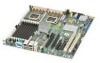
... S5000PSLSASR) NN. Server Board Connector and Component Locations 6 Intel® Server Board S5000PSL PCI Express x8 slot 6 H. SATA 2 or SAS 0 (SAS 0 is available only on product codes S5000PSLSAS and S5000PSLSASR) LL. SATA 5 or SAS 3 (SAS 3 is available only on page 12) M. Front control panel header QQ. Chassis intrusion header Figure ...and S5000PSLSASR) OO. Auxiliary power signal connector V. System fan 2 header Z. USB header CC. RMM connector (connector for Intel® Remote Management Module) K. F. Serial B / emergency management port header TT.
... S5000PSLSASR) NN. Server Board Connector and Component Locations 6 Intel® Server Board S5000PSL PCI Express x8 slot 6 H. SATA 2 or SAS 0 (SAS 0 is available only on product codes S5000PSLSAS and S5000PSLSASR) LL. SATA 5 or SAS 3 (SAS 3 is available only on page 12) M. Front control panel header QQ. Chassis intrusion header Figure ...and S5000PSLSASR) OO. Auxiliary power signal connector V. System fan 2 header Z. USB header CC. RMM connector (connector for Intel® Remote Management Module) K. F. Serial B / emergency management port header TT.

User Guide
Page 28
...LED indicates whether a system is used to read these LEDs. This LED indicates a fault has occurred with system fan 5. See your server chassis documentation for a description of lit POST LEDs is used to read these LEDs. For details about this LED, see the Technical Product...has occurred with several systems, such as in socket DIMM_A1. Replace the faulty FBDIMM. POST LED. Replace the faulty FBDIMM. 10 Intel® Server Board S5000PSL DIMM B1 fault LED Function POST LED. The sequence of how to identify specific errors that might occur during the boot process....
...LED indicates whether a system is used to read these LEDs. This LED indicates a fault has occurred with system fan 5. See your server chassis documentation for a description of lit POST LEDs is used to read these LEDs. For details about this LED, see the Technical Product...has occurred with several systems, such as in socket DIMM_A1. Replace the faulty FBDIMM. POST LED. Replace the faulty FBDIMM. 10 Intel® Server Board S5000PSL DIMM B1 fault LED Function POST LED. The sequence of how to identify specific errors that might occur during the boot process....

User Guide
Page 32
...; RAID Activation Key AXXRAKSW5 accessory to 3.0 Gbps per chassis. However, RAID support is capable of data transfer rates of up to enable RAID 5, see the Intel® Server Board S5000PSL Technical Product Specification. 14 Intel® Server Board S5000PSL This controller is not available. See Figure 2 on the server board continue to function as either SAS or SATA ports. Notes: •...
...; RAID Activation Key AXXRAKSW5 accessory to 3.0 Gbps per chassis. However, RAID support is capable of data transfer rates of up to enable RAID 5, see the Intel® Server Board S5000PSL Technical Product Specification. 14 Intel® Server Board S5000PSL This controller is not available. See Figure 2 on the server board continue to function as either SAS or SATA ports. Notes: •...

User Guide
Page 38
... a USB device anywhere on the server board and act as components of the server board, not as separate products. Intel® Local Control Panel The Intel® Local Control Panel provides enhanced system control by utilizing a LCD display, which provides additional controls and indicators beyond the standard control panel. 20 Intel® Server Board S5000PSL This provides remote control. These...
... a USB device anywhere on the server board and act as components of the server board, not as separate products. Intel® Local Control Panel The Intel® Local Control Panel provides enhanced system control by utilizing a LCD display, which provides additional controls and indicators beyond the standard control panel. 20 Intel® Server Board S5000PSL This provides remote control. These...

User Guide
Page 43
...jumper from the normal operation position, covering pins 2 and 3, to the previous BIOS: 1. BIOS Bank Select Jumper in your server will boot to the previous BIOS until you either move the jumper again or until you may want to revert to the ... the current BIOS, and the BIOS that was previously installed. Open the chassis. See your server contains two versions of the rolling BIOS feature, your chassis documentation for instructions on removing the chassis cover. 3. Close the chassis. 6. Intel® Server Board S5000PSL 25 Note: If you upgrade the BIOS more than once with your BIOS,...
...jumper from the normal operation position, covering pins 2 and 3, to the previous BIOS: 1. BIOS Bank Select Jumper in your server will boot to the previous BIOS until you either move the jumper again or until you may want to revert to the ... the current BIOS, and the BIOS that was previously installed. Open the chassis. See your server contains two versions of the rolling BIOS feature, your chassis documentation for instructions on removing the chassis cover. 3. Close the chassis. 6. Intel® Server Board S5000PSL 25 Note: If you upgrade the BIOS more than once with your BIOS,...

User Guide
Page 44
... in Clear Password Position 5. Power down the system. Power down the server. 7. Leave the AC power cord connected. 2. Power up the server. 26 Intel® Server Board S5000PSL Close the chassis. 9. Open the chassis. Clearing the Password If the user or administrator password(s) is lost or...CLR Default 2 Clear 3 Password J1D2 AF000423 Figure 7. Locate the Password Clear jumper block at board position J1D2. See your chassis documentation for instructions on removing the chassis cover. 3. See Figure 7. 4. The password clear jumper must be restored to its original ...
... in Clear Password Position 5. Power down the system. Power down the server. 7. Leave the AC power cord connected. 2. Power up the server. 26 Intel® Server Board S5000PSL Close the chassis. 9. Open the chassis. Clearing the Password If the user or administrator password(s) is lost or...CLR Default 2 Clear 3 Password J1D2 AF000423 Figure 7. Locate the Password Clear jumper block at board position J1D2. See your chassis documentation for instructions on removing the chassis cover. 3. See Figure 7. 4. The password clear jumper must be restored to its original ...

User Guide
Page 45
... system. Leave the AC power cord connected. 2. See your chassis documentation for instructions on removing the chassis cover. 3. CMOS Clr Jumper in the Clear CMOS Position 5. Close the chassis. 8. Open the chassis. CMOS CLR Default 2 Clear 3 CMOS J1D1 AF000424 Figure 8. Wait 10 seconds. 6. Intel® Server Board S5000PSL 27 Move the jumper from the normal operation position, covering...
... system. Leave the AC power cord connected. 2. See your chassis documentation for instructions on removing the chassis cover. 3. CMOS Clr Jumper in the Clear CMOS Position 5. Close the chassis. 8. Open the chassis. CMOS CLR Default 2 Clear 3 CMOS J1D1 AF000424 Figure 8. Wait 10 seconds. 6. Intel® Server Board S5000PSL 27 Move the jumper from the normal operation position, covering...

User Guide
Page 47
..., DIMM_C1, DIMM_C2, DIMM_D1, and DIMM_D2, starting from the server. 4. Remove the chassis cover. 3 Hardware Installations and Upgrades Before You Begin Before working with your server product, pay close attention to the server. Turn off the server. 3. Disconnect the AC power cord from the inside of ...requirements and options. Turn off all peripheral devices connected to the "Safety Information" on the board for a link to the MCH. DIMM_A1 is the socket closest to the list of the board. Tools and Supplies Needed • Phillips* (cross head) screwdriver (#1 bit and #2...
..., DIMM_C1, DIMM_C2, DIMM_D1, and DIMM_D2, starting from the server. 4. Remove the chassis cover. 3 Hardware Installations and Upgrades Before You Begin Before working with your server product, pay close attention to the server. Turn off the server. 3. Disconnect the AC power cord from the inside of ...requirements and options. Turn off all peripheral devices connected to the "Safety Information" on the board for a link to the MCH. DIMM_A1 is the socket closest to the list of the board. Tools and Supplies Needed • Phillips* (cross head) screwdriver (#1 bit and #2...

User Guide
Page 48
B. DIMM_C1 F. D C B A E F G H AF000093 Callout A. DIMM Socket Callout DIMM Socket DIMM_A1 DIMM_A2 DIMM_B1 DIMM_B2 E. Locating DIMM Sockets 30 Intel® Server Board S5000PSL Disconnect and remove any components necessary to access the DIMM sockets. D. DIMM_C2 G. Locate the DIMM sockets (see Figure 9). 6. DIMM_D1 H. C. DIMM_D2 Figure 9. See the documentation that came with your chassis for instructions on removing chassis components. 5.
B. DIMM_C1 F. D C B A E F G H AF000093 Callout A. DIMM Socket Callout DIMM Socket DIMM_A1 DIMM_A2 DIMM_B1 DIMM_B2 E. Locating DIMM Sockets 30 Intel® Server Board S5000PSL Disconnect and remove any components necessary to access the DIMM sockets. D. DIMM_C2 G. Locate the DIMM sockets (see Figure 9). 6. DIMM_D1 H. C. DIMM_D2 Figure 9. See the documentation that came with your chassis for instructions on removing chassis components. 5.

User Guide
Page 49
... cord. The arrow for instructions on installing the chassis cover. Reinstall and reconnect any parts you removed or disconnected to the open position. See letter "A" in Figure 10. Make sure the clips latch firmly in Figure 10. 12. Intel® Server Board S5000PSL 31 See letter "C" in place. 7. Make ...sure the clips at each end of the FBDIMM with your chassis for instructions on removing...
... cord. The arrow for instructions on installing the chassis cover. Reinstall and reconnect any parts you removed or disconnected to the open position. See letter "A" in Figure 10. Make sure the clips latch firmly in Figure 10. 12. Intel® Server Board S5000PSL 31 See letter "C" in place. 7. Make ...sure the clips at each end of the FBDIMM with your chassis for instructions on removing...

User Guide
Page 50
.... 6. Reinstall and reconnect any components necessary to dissipate the static charge while handling the processor. (2) Avoid moving around unnecessarily. 32 Intel® Server Board S5000PSL See the documentation that came with your chassis for a link to the list of the DIMM socket(s) outward to reach the DIMM sockets. Holding the FBDIMM by doing the following...
.... 6. Reinstall and reconnect any components necessary to dissipate the static charge while handling the processor. (2) Avoid moving around unnecessarily. 32 Intel® Server Board S5000PSL See the documentation that came with your chassis for a link to the list of the DIMM socket(s) outward to reach the DIMM sockets. Holding the FBDIMM by doing the following...

User Guide
Page 51
... these instructions: 1. Turn off all peripheral devices connected to the server. Locate the processor sockets (see Figure 11). See the documentation that came with your chassis for instructions on page iii. 2. Intel® Server Board S5000PSL 33 Remove the chassis cover. Disconnect the AC power cord from the server. 4. Observe the safety and ESD precautions in "Safety Information...
... these instructions: 1. Turn off all peripheral devices connected to the server. Locate the processor sockets (see Figure 11). See the documentation that came with your chassis for instructions on page iii. 2. Intel® Server Board S5000PSL 33 Remove the chassis cover. Disconnect the AC power cord from the server. 4. Observe the safety and ESD precautions in "Safety Information...