
User Guide
Page 7
.../motherboards/server/S3420GP/. In this server board. Product Accessories This server board is available in the Technical Product Specification. This manual is written for system technicians who are responsible for troubleshooting, upgrading, and repairing this chapter, you for purchasing and using the utilities shipped with the following Intel® Server Chassis: • Intel® Server Chassis SC5650UP (Intel® Server Board S3420GPLX and S3420GPLC) • Intel...
.../motherboards/server/S3420GP/. In this server board. Product Accessories This server board is available in the Technical Product Specification. This manual is written for system technicians who are responsible for troubleshooting, upgrading, and repairing this chapter, you for purchasing and using the utilities shipped with the following Intel® Server Chassis: • Intel® Server Chassis SC5650UP (Intel® Server Board S3420GPLX and S3420GPLC) • Intel...

User Guide
Page 20
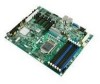
... ports on two USB/LAN combo at rear of the server board. Table 2 summarizes the features of board. Support for optional Intel® Remote Management Module 3 (Intel® Server board S3420GPLX) 18 Intel® Server Board S3420GP User Guide PCI Express* switch • Intel® Server Board S3420GPLC: - ServerEngines* LLC Pilot II BMC controller (Integrated BMC) - Server Board Features Feature Processor Memory Chipset I/O Control Description Support for...
... ports on two USB/LAN combo at rear of the server board. Table 2 summarizes the features of board. Support for optional Intel® Remote Management Module 3 (Intel® Server board S3420GPLX) 18 Intel® Server Board S3420GP User Guide PCI Express* switch • Intel® Server Board S3420GPLC: - ServerEngines* LLC Pilot II BMC controller (Integrated BMC) - Server Board Features Feature Processor Memory Chipset I/O Control Description Support for...
User Guide
Page 21
...). - Slot6: One PCI Express* Gen2 x16 (x8 throughput) connector). • Intel® Server Board S3420GPLX/S3420GPLC Five 4-pin fan headers supporting four system fans and one processor • Intel® Server Board S3420GPV Four 4-pin fan headers supporting four system fans and one processor • Intel® Server Board S3420GPLX/S3420GPLC On-board ServerEngines* LLC Pilot II BMC Controller - Up to four SAS hard...
...). - Slot6: One PCI Express* Gen2 x16 (x8 throughput) connector). • Intel® Server Board S3420GPLX/S3420GPLC Five 4-pin fan headers supporting four system fans and one processor • Intel® Server Board S3420GPV Four 4-pin fan headers supporting four system fans and one processor • Intel® Server Board S3420GPLX/S3420GPLC On-board ServerEngines* LLC Pilot II BMC Controller - Up to four SAS hard...

User Guide
Page 22
... PCI-E x1 interface Intel® Server Board S3420GPLX/S3420GPLC: On-board LLC Pilot II BMC Controller (iBMC) • Integrated Baseboard Management Controller (Integrated BMC), IPMI 2.0 compliant • Integrated 2D video controller on the PCH. Remote Management Module III (RMM3) 20 Intel® Server Board S3420GP User Guide Intel® Server Board S3420GPLX • Intel® Embedded Server RAID Technology II through optional Intel® SAS Entry...
... PCI-E x1 interface Intel® Server Board S3420GPLX/S3420GPLC: On-board LLC Pilot II BMC Controller (iBMC) • Integrated Baseboard Management Controller (Integrated BMC), IPMI 2.0 compliant • Integrated 2D video controller on the PCH. Remote Management Module III (RMM3) 20 Intel® Server Board S3420GP User Guide Intel® Server Board S3420GPLX • Intel® Embedded Server RAID Technology II through optional Intel® SAS Entry...

User Guide
Page 25
...(Default) If these pins are cleared on the next reset. NOTE: The system will occur during a system reset.. Intel® Server Board S3420GP User Guide 23 NOTE: These pins should not be cleared on the next reset. These pins should have a ... Recover Password Clear 2 J1F2 3 Default Password Clear CMOS Clear 2 J1F5 3 Default CLEAR CMOS Jumper Name Pins J1A2: BMC Force Update 1-2 (Intel® Server Board S3420GPLX and S3420GPLC) 2-3 J1F2: Password Clear 1-2 2-3 J1F5: CMOS Clear 1-2 2-3 J1F3: BIOS Recovery 1-2 2-3 What will boot from EFI-bootable recovery media with...
...(Default) If these pins are cleared on the next reset. NOTE: The system will occur during a system reset.. Intel® Server Board S3420GP User Guide 23 NOTE: These pins should not be cleared on the next reset. These pins should have a ... Recover Password Clear 2 J1F2 3 Default Password Clear CMOS Clear 2 J1F5 3 Default CLEAR CMOS Jumper Name Pins J1A2: BMC Force Update 1-2 (Intel® Server Board S3420GPLX and S3420GPLC) 2-3 J1F2: Password Clear 1-2 2-3 J1F5: CMOS Clear 1-2 2-3 J1F3: BIOS Recovery 1-2 2-3 What will boot from EFI-bootable recovery media with...
User Guide
Page 39
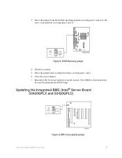
... jumper back to the reset / clear position (covering pins 2 and 3). Wait five seconds. 5. BMC Force Update Jumper Intel® Server Board S3420GP User Guide 37 CMOS Recovery Jumper 4. CMOS Clear 2 J1F5 3 Default CLEAR CMOS AF003182 Figure 8. Close the server chassis. 7. 3. Updating the Integrated BMC (Intel® Server Board S3420GPLX and S3420GPLC) BMC Force Update 2 J1A2 3 Default Enabled AF003291 Figure 9.
... jumper back to the reset / clear position (covering pins 2 and 3). Wait five seconds. 5. BMC Force Update Jumper Intel® Server Board S3420GP User Guide 37 CMOS Recovery Jumper 4. CMOS Clear 2 J1F5 3 Default CLEAR CMOS AF003182 Figure 8. Close the server chassis. 7. 3. Updating the Integrated BMC (Intel® Server Board S3420GPLX and S3420GPLC) BMC Force Update 2 J1A2 3 Default Enabled AF003291 Figure 9.

User Guide
Page 53
...BIOS sends a value of ACh to identify the last POST process executed. The Diagnostic LED #7 is labeled as follows: Intel® Server Board S3420GP User Guide 51 Diagnostic LED #0 (LSB LED) Figure 21. Appendix A: LED Decoder During the system boot process, ... #6 F. Diagnostic LED #5 G. Diagnostic LED #2 J. The lower nibble bits are represented by Diagnostics LEDs #0, #1, #2, and #3. Status LED (Intel® Server Board S3420GPLX and S3420GPLC) D. The LEDs are divided into two nibbles: an upper nibble and a lower nibble. ID LED C. Diagnostic LED #7 (MSB LED) E. ...
...BIOS sends a value of ACh to identify the last POST process executed. The Diagnostic LED #7 is labeled as follows: Intel® Server Board S3420GP User Guide 51 Diagnostic LED #0 (LSB LED) Figure 21. Appendix A: LED Decoder During the system boot process, ... #6 F. Diagnostic LED #5 G. Diagnostic LED #2 J. The lower nibble bits are represented by Diagnostics LEDs #0, #1, #2, and #3. Status LED (Intel® Server Board S3420GPLX and S3420GPLC) D. The LEDs are divided into two nibbles: an upper nibble and a lower nibble. ID LED C. Diagnostic LED #7 (MSB LED) E. ...
