
Product Specification
Page 10
... 12. Intel® Server Board S3210SHLC Layout Reference 8 Table 3. Processor Support Matrix 17 Table 4. Supported DDR2 Modules 19 Table 6. Segment E Configuration IDs 21 Table 7. Memory Bank Labels and DIMM Population Order 28 Table 11. PCI Bus Segment Characteristics 30 Table 13. Segment A Arbitration Connections 31 Table 15. Interrupt Definitions...33 Table 17. BIOS Setup Page...
... 12. Intel® Server Board S3210SHLC Layout Reference 8 Table 3. Processor Support Matrix 17 Table 4. Supported DDR2 Modules 19 Table 6. Segment E Configuration IDs 21 Table 7. Memory Bank Labels and DIMM Population Order 28 Table 11. PCI Bus Segment Characteristics 30 Table 13. Segment A Arbitration Connections 31 Table 15. Interrupt Definitions...33 Table 17. BIOS Setup Page...

Product Specification
Page 22
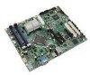
... Panel Header Z SATA 3 AA SATA 5 BB SATA 4 CC Internal USB DD External USB EE CMOS Clear Jumper FF BIOS Jumper GG NIC1 NVM Protect Mode Jumper HH Serial Port 8 Revision 1.3 Intel® Server Board S3210SHLC Diagram Table 2. Intel® Server Board S3210SHLC Layout Reference Ref Description A PCI (32bit/33MHz) Slot 1 B PCI (32bit/33MHz) Slot 2 C PCI Express* x8 (x8 lane...
... Panel Header Z SATA 3 AA SATA 5 BB SATA 4 CC Internal USB DD External USB EE CMOS Clear Jumper FF BIOS Jumper GG NIC1 NVM Protect Mode Jumper HH Serial Port 8 Revision 1.3 Intel® Server Board S3210SHLC Diagram Table 2. Intel® Server Board S3210SHLC Layout Reference Ref Description A PCI (32bit/33MHz) Slot 1 B PCI (32bit/33MHz) Slot 2 C PCI Express* x8 (x8 lane...


