

Data Sheet
Page 3
...11 2.1.1 Core Low-Power State Descriptions 13 2.1.1.1 2.1.1.2 2.1.1.3 2.1.1.4 2.1.1.5 2.1.1.6 2.1.1.7 Core C0 State 13 Core C1/AutoHALT Powerdown State 13 Core C1/MWAIT Powerdown State 14 Core C2 State 14 Core C3 State 14 Core C4 State 14 Core Deep ...Processor DC Specifications 32 4 Package Mechanical Specifications and Pin Information 51 4.1 Package Mechanical Specifications 51 4.2 Processor Pinout and Pin List 59 4.3 Alphabetical Signals Reference 93 5 Thermal Specifications and Design Considerations 101 5.1 Monitoring Die Temperature 108 5.1.1 Thermal Diode 108 5.1.2 Intel...
...11 2.1.1 Core Low-Power State Descriptions 13 2.1.1.1 2.1.1.2 2.1.1.3 2.1.1.4 2.1.1.5 2.1.1.6 2.1.1.7 Core C0 State 13 Core C1/AutoHALT Powerdown State 13 Core C1/MWAIT Powerdown State 14 Core C2 State 14 Core C3 State 14 Core C4 State 14 Core Deep ...Processor DC Specifications 32 4 Package Mechanical Specifications and Pin Information 51 4.1 Package Mechanical Specifications 51 4.2 Processor Pinout and Pin List 59 4.3 Alphabetical Signals Reference 93 5 Thermal Specifications and Design Considerations 101 5.1 Monitoring Die Temperature 108 5.1.1 Thermal Diode 108 5.1.2 Intel...
Data Sheet
Page 19
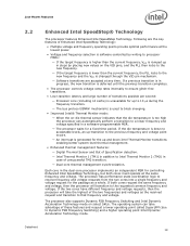
... to the new frequency. - If the die temperature is generated for controlling Enhanced Intel SpeedStep Technology, but both cores request the same frequency and voltage, then the processor will take advantage of Specification detection. - Dual-core thermal management synchronization. The processor also supports Dynamic FSB Frequency Switching and Intel Dynamic Acceleration Technology mode on the VID pins...
... to the new frequency. - If the die temperature is generated for controlling Enhanced Intel SpeedStep Technology, but both cores request the same frequency and voltage, then the processor will take advantage of Specification detection. - Dual-core thermal management synchronization. The processor also supports Dynamic FSB Frequency Switching and Intel Dynamic Acceleration Technology mode on the VID pins...
Data Sheet
Page 29
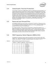
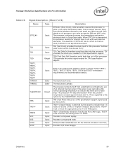
...signals are used for test purposes internally and can be high enough that the processor cannot be connected through a resistor to ground (VSS). If the external thermal sensor detects a catastrophic processor temperature of approximately 125°C (maximum), or if the THERMTRIP# signal is ...Encoding for BCLK[1:0] is asserted, the VCC supply to the processor must remain unconnected. The TEST1,TEST2,TEST3,TEST4,TEST5,TEST6,TEST7 pins are used to protect the processor and the system against excessive temperatures. THERMTRIP# functionality is not ensured if the PWRGOOD signal is...
...signals are used for test purposes internally and can be high enough that the processor cannot be connected through a resistor to ground (VSS). If the external thermal sensor detects a catastrophic processor temperature of approximately 125°C (maximum), or if the THERMTRIP# signal is ...Encoding for BCLK[1:0] is asserted, the VCC supply to the processor must remain unconnected. The TEST1,TEST2,TEST3,TEST4,TEST5,TEST6,TEST7 pins are used to protect the processor and the system against excessive temperatures. THERMTRIP# functionality is not ensured if the PWRGOOD signal is...
Data Sheet
Page 31
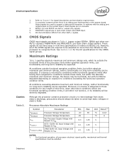
... maximum and minimum ratings only, which lie outside functional operation condition limits, but with Respect to BCLK[1:0]. Although the processor contains protective circuitry to avoid high static voltages or electric fields. BPM[2:1]# and PRDY# are no debug port implemented ... conditions outside these conditions for the processor to support a debug port interposer. Processor Absolute Maximum Ratings Symbol Parameter TSTORAGE TSTORAGE VCC VinAGTL+ VinAsynch_CMOS Processor Storage Temperature Processor Storage Temperature Any Processor Supply Voltage with Respect to VSS AGTL...
... maximum and minimum ratings only, which lie outside functional operation condition limits, but with Respect to BCLK[1:0]. Although the processor contains protective circuitry to avoid high static voltages or electric fields. BPM[2:1]# and PRDY# are no debug port implemented ... conditions outside these conditions for the processor to support a debug port interposer. Processor Absolute Maximum Ratings Symbol Parameter TSTORAGE TSTORAGE VCC VinAGTL+ VinAsynch_CMOS Processor Storage Temperature Processor Storage Temperature Any Processor Supply Voltage with Respect to VSS AGTL...

Data Sheet
Page 32
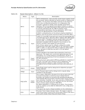
...include any signal will not affect the long-term reliability of the device. Failure to adhere to the processor case temperature specifications. 4. The tables list the DC specifications for Processors Processor Number Core Frequency/Voltage X9100 3.06 GHz & VCCHFM 1.6 GHz & VCCLFM 0.8 GHz & VCCSLFM Min 1.0 ... a voltage bias. For Intel® Core™2 Duo mobile processors in 22x22 mm package. 3.10 Processor DC Specifications The processor DC specifications in order to the processor. 3. Read all states except in Enhanced Intel® Dynamic Acceleration Technology ...
...include any signal will not affect the long-term reliability of the device. Failure to adhere to the processor case temperature specifications. 4. The tables list the DC specifications for Processors Processor Number Core Frequency/Voltage X9100 3.06 GHz & VCCHFM 1.6 GHz & VCCLFM 0.8 GHz & VCCSLFM Min 1.0 ... a voltage bias. For Intel® Core™2 Duo mobile processors in 22x22 mm package. 3.10 Processor DC Specifications The processor DC specifications in order to the processor. 3. Read all states except in Enhanced Intel® Dynamic Acceleration Technology ...
Data Sheet
Page 97
... to ensure recognition of this signal following an input/output write instruction, it will go active when the processor temperature monitoring sensor detects that the processor Thermal Control Circuit (TCC) has been activated, if enabled. Probe Ready signal used by the system will...INIT# is enabled by debug tools to -inactive transition of RESET#, then the processor executes its maximum safe operating temperature. Because the APIC is sampled active on the Pentium processor. This enables symmetric agents to retain ownership of the FSB throughout the bus locked...
... to ensure recognition of this signal following an input/output write instruction, it will go active when the processor temperature monitoring sensor detects that the processor Thermal Control Circuit (TCC) has been activated, if enabled. Probe Ready signal used by the system will...INIT# is enabled by debug tools to -inactive transition of RESET#, then the processor executes its maximum safe operating temperature. Because the APIC is sampled active on the Pentium processor. This enables symmetric agents to retain ownership of the FSB throughout the bus locked...
Data Sheet
Page 99
... details. TCK (Test Clock) provides the clock input for the internal processor core PLLs. This sensor is set well above the normal operating temperature to ensure that it is a JTAG specification support signal used by the THERMTRIP# (Thermal Trip) pin. Processor core ground node. Processor I/O Power Supply. TDI provides the serial input needed for JTAG specification...
... details. TCK (Test Clock) provides the clock input for the internal processor core PLLs. This sensor is set well above the normal operating temperature to ensure that it is a JTAG specification support signal used by the THERMTRIP# (Thermal Trip) pin. Processor core ground node. Processor I/O Power Supply. TDI provides the serial input needed for JTAG specification...
Data Sheet
Page 101
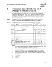
... the processor currents at higher temperatures and extrapolating the values for the optimal operation and long-term reliability of 35 oC Datasheet 101 Processor TDP requirements in Intel Dynamic Acceleration... Technology mode are determined by the activation of the on-die Intel Thermal Monitor. The TDP specification should be enabled for the Dual-Core Extreme Edition Processor Symbol Processor Number Core...
... the processor currents at higher temperatures and extrapolating the values for the optimal operation and long-term reliability of 35 oC Datasheet 101 Processor TDP requirements in Intel Dynamic Acceleration... Technology mode are determined by the activation of the on-die Intel Thermal Monitor. The TDP specification should be enabled for the Dual-Core Extreme Edition Processor Symbol Processor Number Core...
Data Sheet
Page 102
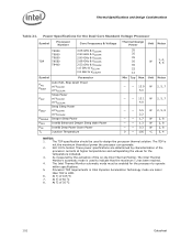
...; Deep Power Down Power Junction Temperature Thermal Design Power 35 35 35 35 35 22 12 Min Typ Max Unit W Unit Notes 1, 4, 5, 6 Notes - - 13.9 W 2, 5, 7 5.0 - - 13.1 W 2, 5, 7 4.8 - - 5.5 2.2 W 2, 5, 8 - - 1.7 W 2, 8 - - 1.3 W 2, 8 - - 0.3 W 2, 8 0 - 105 °C 3, 4 NOTES: 1. At Tj of the on-die Intel Thermal Monitor. Power Specifications for the Dual-Core Standard Voltage Processor Symbol Processor Number Core Frequency & Voltage TDP T9900 T9800 T9600...
...; Deep Power Down Power Junction Temperature Thermal Design Power 35 35 35 35 35 22 12 Min Typ Max Unit W Unit Notes 1, 4, 5, 6 Notes - - 13.9 W 2, 5, 7 5.0 - - 13.1 W 2, 5, 7 4.8 - - 5.5 2.2 W 2, 5, 8 - - 1.7 W 2, 8 - - 1.3 W 2, 8 - - 0.3 W 2, 8 0 - 105 °C 3, 4 NOTES: 1. At Tj of the on-die Intel Thermal Monitor. Power Specifications for the Dual-Core Standard Voltage Processor Symbol Processor Number Core Frequency & Voltage TDP T9900 T9800 T9600...

Data Sheet
Page 103
... 35 oC Datasheet 103 The Intel Thermal Monitor's automatic mode is not the maximum theoretical power the processor can generate. 2. The TDP specification should be enabled for the temperature indicated. 3. These power specifications are lesser than TDP in Standard Package Symbol Processor Number Core Frequency & Voltage TDP P9700 P9600 P8800 P9500 P8700 P8600 P8400 2.8 GHz & VCCHFM...
... 35 oC Datasheet 103 The Intel Thermal Monitor's automatic mode is not the maximum theoretical power the processor can generate. 2. The TDP specification should be enabled for the temperature indicated. 3. These power specifications are lesser than TDP in Standard Package Symbol Processor Number Core Frequency & Voltage TDP P9700 P9600 P8800 P9500 P8700 P8600 P8400 2.8 GHz & VCCHFM...
Data Sheet
Page 104
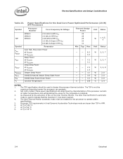
... at VCCSLFM Deeper Sleep Power Intel® Enhanced Deeper Sleep State Power Intel® Deep Power Down Power Junction Temperature Min 25 25 25 20 11 Typ Max W 1, 4, 5, 6 Unit Notes - - 8.3 3.3 W 2, 5, 7 - - 7.5 3.1 W 2, 5, 7 - - 2.9 1.8 W 2, 5, 8 - - 1.0 W 2, 8 - - 0.9 W 2, 8 - - 0.3 W 2, 8 0 - 105 °C 3, 4 NOTES: 1. The Intel Thermal Monitor's automatic mode is not the maximum theoretical power the processor can generate. 2. Processor TDP requirements in HFM. 6. At Tj...
... at VCCSLFM Deeper Sleep Power Intel® Enhanced Deeper Sleep State Power Intel® Deep Power Down Power Junction Temperature Min 25 25 25 20 11 Typ Max W 1, 4, 5, 6 Unit Notes - - 8.3 3.3 W 2, 5, 7 - - 7.5 3.1 W 2, 5, 7 - - 2.9 1.8 W 2, 5, 8 - - 1.0 W 2, 8 - - 0.9 W 2, 8 - - 0.3 W 2, 8 0 - 105 °C 3, 4 NOTES: 1. The Intel Thermal Monitor's automatic mode is not the maximum theoretical power the processor can generate. 2. Processor TDP requirements in HFM. 6. At Tj...
Data Sheet
Page 105
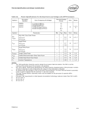
...processor thermal solution. The Intel Thermal Monitor's automatic mode is not the maximum theoretical power the processor can generate. 2. Thermal Specifications and Design Considerations Table 24. Power Specifications fro the Dual-Core Low Voltage (LV) SFF Processors Symbol TDP Processor Number SL9600 SL9400 SL9300 Core...be used to operate within specifications. 5. At Tj of the processor currents at VCCSLFM Deeper Sleep Power Intel® Enhanced Deeper Sleep State Power Intel® Deep Power Down Power Junction Temperature Thermal Design Power 17 17 17 16.7 10 Min Typ ...
...processor thermal solution. The Intel Thermal Monitor's automatic mode is not the maximum theoretical power the processor can generate. 2. Thermal Specifications and Design Considerations Table 24. Power Specifications fro the Dual-Core Low Voltage (LV) SFF Processors Symbol TDP Processor Number SL9600 SL9400 SL9300 Core...be used to operate within specifications. 5. At Tj of the processor currents at VCCSLFM Deeper Sleep Power Intel® Enhanced Deeper Sleep State Power Intel® Deep Power Down Power Junction Temperature Thermal Design Power 17 17 17 16.7 10 Min Typ ...

Data Sheet
Page 106
As measured by characterization of the processor currents at VCCSLFM Deeper Sleep Power Intel® Enhanced Deeper Sleep state Power Intel® Deep Power Down Power Junction Temperature Thermal Design Power 10 10 10 10 8 Min Typ Max Unit W Unit Notes 1, 4, 5, 6 Notes - - 2.9 1.6 2.5 - - 1.4 W 2, 5, 7 W 2, 5, 7 - - 1.3 0.9 W 2, 5, 8 - - 0.6 W 2, 8 - - 0.4 W 2, 8 - - 0.25 W 2, 8 0 - 105 °C 3, 4 NOTES: 1. The Intel Thermal Monitor automatic mode must be used to...
As measured by characterization of the processor currents at VCCSLFM Deeper Sleep Power Intel® Enhanced Deeper Sleep state Power Intel® Deep Power Down Power Junction Temperature Thermal Design Power 10 10 10 10 8 Min Typ Max Unit W Unit Notes 1, 4, 5, 6 Notes - - 2.9 1.6 2.5 - - 1.4 W 2, 5, 7 W 2, 5, 7 - - 1.3 0.9 W 2, 5, 8 - - 0.6 W 2, 8 - - 0.4 W 2, 8 - - 0.25 W 2, 8 0 - 105 °C 3, 4 NOTES: 1. The Intel Thermal Monitor automatic mode must be used to...
Data Sheet
Page 107
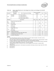
... Sleep state Power Intel® Deep Power Down Power Junction Temperature Thermal Design Power 5.5 5.5 5.5 5 Min Typ Max Unit W Unit Notes 1, 4, 5, 6 Notes - - 2.1 1.4 W 2, 5, 7 - - 1.8 1.2 W 2, 5, 7 - - 0.7 0.6 W 2, 5, 8 - - 0.4 W 2, 8 - - 0.3 W 2, 8 - - 0.2 W 2, 8 0 - 100 °C 3, 4 NOTES: 1. The TDP specification should be enabled for the Single-Core Ultra-Low-Voltage (5.5 W) SFF Processors Symbol TDP Symbol PAH, PSGNT PSLP PDSLP PDPRSLP PDC4 PC6 TJ Processor Number Core Frequency & Voltage SU3500...
... Sleep state Power Intel® Deep Power Down Power Junction Temperature Thermal Design Power 5.5 5.5 5.5 5 Min Typ Max Unit W Unit Notes 1, 4, 5, 6 Notes - - 2.1 1.4 W 2, 5, 7 - - 1.8 1.2 W 2, 5, 7 - - 0.7 0.6 W 2, 5, 8 - - 0.4 W 2, 8 - - 0.3 W 2, 8 - - 0.2 W 2, 8 0 - 100 °C 3, 4 NOTES: 1. The TDP specification should be enabled for the Single-Core Ultra-Low-Voltage (5.5 W) SFF Processors Symbol TDP Symbol PAH, PSGNT PSLP PDSLP PDPRSLP PDC4 PC6 TJ Processor Number Core Frequency & Voltage SU3500...
Data Sheet
Page 108
... case, the assumption is that the beta of the transistor does not impact the calculated temperature values. To accurately calculate silicon temperature use a full bipolar junction transistor-type model. This offset is built on Intel's advanced 45-nm processor technology. Table 27 and Table 28 provide the diode interface and transistor model specifications. For...
... case, the assumption is that the beta of the transistor does not impact the calculated temperature values. To accurately calculate silicon temperature use a full bipolar junction transistor-type model. This offset is built on Intel's advanced 45-nm processor technology. Table 27 and Table 28 provide the diode interface and transistor model specifications. For...

Data Sheet
Page 109
... designed and characterized thermal solution, the TCC would only be modulated by initiating an Enhanced Intel SpeedStep Technology transition when the processor silicon reaches its maximum operating temperature. The Intel Thermal Monitor controls the processor temperature by modulating (starting and stopping) the processor core clocks or by alternately turning the clocks off and on -demand mode. Once the...
... designed and characterized thermal solution, the TCC would only be modulated by initiating an Enhanced Intel SpeedStep Technology transition when the processor silicon reaches its maximum operating temperature. The Intel Thermal Monitor controls the processor temperature by modulating (starting and stopping) the processor core clocks or by alternately turning the clocks off and on -demand mode. Once the...

Data Sheet
Page 110
... features are collectively referred to help cool down the processor. Please ensure this feature is lower than the TM2 transition-based target frequency, the processor will be activated immediately independent of the processor temperature. Intel recommends TM1 and TM2 be modified. If the processor load-based Enhanced Intel SpeedStep Technology transition target frequency is enabled and supported...
... features are collectively referred to help cool down the processor. Please ensure this feature is lower than the TM2 transition-based target frequency, the processor will be activated immediately independent of the processor temperature. Intel recommends TM1 and TM2 be modified. If the processor load-based Enhanced Intel SpeedStep Technology transition target frequency is enabled and supported...

Data Sheet
Page 111
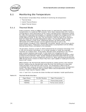
... feature must be used as a safeguard to monitor and control the state of the Intel Thermal Monitor feature. Each core of the processor will have a unique digital thermal sensor whose temperature is disabled, the processor will automatically shut down within its temperature operating specifications. The system designer is the responsibility of software to convert the relative...
... feature must be used as a safeguard to monitor and control the state of the Intel Thermal Monitor feature. Each core of the processor will have a unique digital thermal sensor whose temperature is disabled, the processor will automatically shut down within its temperature operating specifications. The system designer is the responsibility of software to convert the relative...
Data Sheet
Page 112
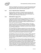
... Developer's Manuals for specific register and programming details. Refer to the temperature can be noted that it is asserted when the processor die temperature has reached its TDP. PROCHOT# Signal Pin An external signal, PROCHOT# (processor hot), is anticipated that Intel recommends both processor cores will enter the lowest programmed TM2 performance state. Refer to monitor the...
... Developer's Manuals for specific register and programming details. Refer to the temperature can be noted that it is asserted when the processor die temperature has reached its TDP. PROCHOT# Signal Pin An external signal, PROCHOT# (processor hot), is anticipated that Intel recommends both processor cores will enter the lowest programmed TM2 performance state. Refer to monitor the...

Product Manual
Page 1
... V DC 2 - 10 V DC Note: Decimal point shown in display units +/- Refer to user guide (available from setpoint in table indicates temperature resolution of 0.1° Parameter Lower Upper Adjustment range & Description Default Display Display Value Scale Range Upper Limit Scale Range Lower Limit +100 to Range...Decimal point position Process Variable Offset Limit Action Setpoint Upper Limit Setpoint Lower Limit =XXXX, =XXX.X, =XX.XX, =X.XXX (non-temperature ranges only) ±Span of controller (see CAUTION note at which output will be maximum) Range max Retransmit Output 3 Scale ...
... V DC 2 - 10 V DC Note: Decimal point shown in display units +/- Refer to user guide (available from setpoint in table indicates temperature resolution of 0.1° Parameter Lower Upper Adjustment range & Description Default Display Display Value Scale Range Upper Limit Scale Range Lower Limit +100 to Range...Decimal point position Process Variable Offset Limit Action Setpoint Upper Limit Setpoint Lower Limit =XXXX, =XXX.X, =XX.XX, =X.XXX (non-temperature ranges only) ±Span of controller (see CAUTION note at which output will be maximum) Range max Retransmit Output 3 Scale ...