Intel HH80557PH0462M - Core 2 Duo 2.13 GHz Processor Support and Manuals
Get Help and Manuals for this Intel item
View All Support Options Below
Free Intel HH80557PH0462M manuals!
Problems with Intel HH80557PH0462M?
Ask a Question
Free Intel HH80557PH0462M manuals!
Problems with Intel HH80557PH0462M?
Ask a Question
Popular Intel HH80557PH0462M Manual Pages
Mechanical Design Guidelines - Page 5
... Material Area 81 C.3 Interface Material Performance 81
Case Temperature Reference Metrology 83 D.1 Objective and Scope 83 D.2 Supporting Test Equipment 83 D.3 Thermal Calibration and Controls 85...Installation 98 D.6 Thermocouple Wire Management 102
Balanced Technology Extended (BTX) System Thermal Considerations 103
Fan Performance for Reference Design 107
Mechanical Drawings 109
Intel&#...
Mechanical Design Guidelines - Page 6
...Temperature, Passive Heatsink ... 29 Figure 4-1. Intel® Type II TMA 65W Reference Design 47 Figure 5-5. E18764-001 Reference Design - Reference Clip/Heatsink Assembly 61 Figure 6-7. Load Cell Installation... Limit ....... 73 Figure 7-8. Cutting Solder 94 Figure 7-26. Processor Case Temperature Measurement Location 17 Figure 2-3. Omega Thermocouple 84 Figure 7-12. 775...
Mechanical Design Guidelines - Page 7
... Temperature of Intel® Boxed Processor Thermal Solutions.22 Table 5-1. Heatsink Inlet Temperature of Intel&#...Board Deflection Configuration Definitions 70 Table 7-2. Solder Station Setup 96 Figure 7-28. Removing Excess Solder 99 Figure...Installation 101 Figure 7-37. Sheet 3 122 Figure 7-53. Intel® E18764-001 Reference Solution Assembly 124
Tables
Table 2-1. Processor Preload Limits...
Mechanical Design Guidelines - Page 10
...Series Datasheet.
Chapter 5 gives information on the Intel reference thermal solution for the processor in this document discusses package thermal mechanical requirements to validate a processor thermal solution. The physical dimensions and thermal specifications of the processor that this means ATX reference designs (E18764-001) supported by this document, when a reference is made...
Mechanical Design Guidelines - Page 17
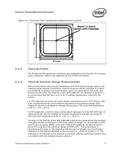
..., an active air-cooled design, assumed be designed to manage the processor TDP at an inlet temperature of systems and environments need to the system. The slope of the thermal profile was established assuming a generational improvement in ATX Chassis, with a fan installed at the top of the heatsink equivalent to Section 3.1). For an...
Mechanical Design Guidelines - Page 18
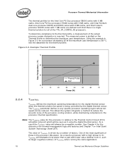
... Circuit (TCC) activation set point which will be a negative number. See Chapter 4 for the discussion the thermal management logic and features and Chapter 7 on the Thermal Profile to the processor thermal specification. One of the most significant of the processor cooling solution, while maintaining compliance to determine the maximum case temperature. Using the example in...
Mechanical Design Guidelines - Page 23
...23 Contact your Intel field sales representative for package and heatsink installation and removal is a function of chassis design.
• The thermal design power (TDP) of the processor, and the corresponding...These parameters are usually combined in heatsink design include:
• The local ambient temperature TA at the entire system level, accounting for the thermal requirements of each of...
Mechanical Design Guidelines - Page 33
... two operating points, each consisting of the processor, providing a temperature reduction. The voltage regulator must support VID transitions in processor power consumption. A processor enabled for the processor. Each step will transition to the new core operating voltage by dropping the bus-to-core multiplier to execute instructions during the voltage transition. This transition occurs...
Mechanical Design Guidelines - Page 34
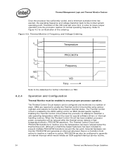
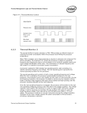
Refer to -active. Figure 4-2. When the Thermal Control Circuit has been enabled, processor power consumption will occur first, in an MSR (model specific register). Operation and Configuration
Thermal Monitor must be reduced after the thermal sensor detects a high temperature (that is, PROCHOT# assertion). The Thermal Control Circuit is a transition from active-to-inactive or inactive...
Mechanical Design Guidelines - Page 35

... duty cycle, the maximum time period the clocks are then evaluated in the processor datasheet. This is used simultaneously, the fixed duty cycle determined by setting bits in steps of 7/8 (87.5%), the clock on time would take precedence. In a high temperature situation, if the thermal control circuit and ACPI MSRs (automatic and on...
Mechanical Design Guidelines - Page 37
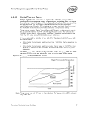
...). Since the DTS is factory set on -die sensor to use ...-part basis there is no thermal diode.
The usage model for the measured power dissipation.
The DTS TCONTROL value is factory configured and is relevant only to noise. The processor uses... the DTS are relative to the activation of the processor than or equal to TCONTROL, then TC must be updated at or below :
• If the Digital ...
Mechanical Design Guidelines - Page 40
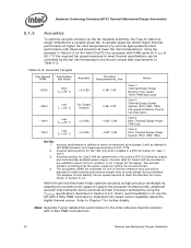
...processor workloads by adapting the maximum fan speed to support the processor thermal profile, additional acoustic improvements can be achieved at higher fan inlet temperatures...5-2. Acoustic Targets
Fan Speed RPM
Thermistor Set Point
Acoustic
Thermal Requirements, Ψca... the TMA only when installed in a BTX S2...model is to meet the effective fan curve shown in Section 2.2.4. Intel...
Mechanical Design Guidelines - Page 68

... and initial settings for availability of these tools.
7.4
Fan Hub Thermistor and Intel® QST
There is generated using the PWM duty cycle to accelerate the fan up to the limit imposed by measuring the processor Digital thermal sensor, will determine the maximum fan speed as a function of the inlet ambient temperature and by...
Mechanical Design Guidelines - Page 78

...temperature compensated up to 121 °C (operating), but their uncertainty increases according to operate in the high end of the force reading at no applied load, it to be included in the test setup... Examples
The following load cell vendor's instructions.
78
Thermal and Mechanical Design Guidelines www.sensotec.com
Vishay* Measurements Group Model 6100 scanner with your load cell vendor...
Mechanical Design Guidelines - Page 79
...socket. 3. Install relevant test vehicle (TTV, processor) in Figure 7-10, and actuate attach mechanism. 4. Repeat time-zero, room temperature preload measurement 3. Place unit into room temperature
conditions 6. ... appropriate support fixture that is generally specified by the actual heatsink mechanism.
2. Record the preload measurement (total from thermal chamber and set into preheated...
Intel HH80557PH0462M Reviews
We have not received any reviews for Intel yet.