Product Specification
Page 3
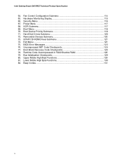
... personal injury. The TPS describes the standard product and available manufacturing options. Preface This Technical Product Specification (TPS) specifies the Intel® Desktop Board D875PBZ layout, components, connectors, power and environmental requirements, and BIOS. It is intended to provide detailed,... information. Not all of these symbols and abbreviations appear in all specifications of the BIOS error messages, beep codes, and POST codes Typographical Conventions This section contains information about the Desktop Board and its components to the vendors, system integrators, ...
... personal injury. The TPS describes the standard product and available manufacturing options. Preface This Technical Product Specification (TPS) specifies the Intel® Desktop Board D875PBZ layout, components, connectors, power and environmental requirements, and BIOS. It is intended to provide detailed,... information. Not all of these symbols and abbreviations appear in all specifications of the BIOS error messages, beep codes, and POST codes Typographical Conventions This section contains information about the Desktop Board and its components to the vendors, system integrators, ...
Product Specification
Page 7
... 3.8.3 Booting Without Attached Devices 90 3.8.4 Changing the Default Boot Device During POST 91 3.9 Fast Booting Systems with Intel® Rapid BIOS Boot 91 3.9.1 Peripheral Selection and Configuration 91 3.9.2 Intel Rapid BIOS Boot 92 3.10 BIOS Security Features 93 4 BIOS Setup Program 4.1 Introduction...95 4.2 Maintenance Menu ... 4.7.3 Removable Devices Submenu 120 4.7.4 ATAPI CD-ROM Drives Submenu 121 4.8 Exit Menu ...121 5 Error Messages and Beep Codes 5.1 BIOS Error Messages 123 5.2 Port 80h POST Codes 125 5.3 Bus Initialization Checkpoints 129 5.4 Speaker ...130 5.5 BIOS Beep...
... 3.8.3 Booting Without Attached Devices 90 3.8.4 Changing the Default Boot Device During POST 91 3.9 Fast Booting Systems with Intel® Rapid BIOS Boot 91 3.9.1 Peripheral Selection and Configuration 91 3.9.2 Intel Rapid BIOS Boot 92 3.10 BIOS Security Features 93 4 BIOS Setup Program 4.1 Introduction...95 4.2 Maintenance Menu ... 4.7.3 Removable Devices Submenu 120 4.7.4 ATAPI CD-ROM Drives Submenu 121 4.8 Exit Menu ...121 5 Error Messages and Beep Codes 5.1 BIOS Error Messages 123 5.2 Port 80h POST Codes 125 5.3 Bus Initialization Checkpoints 129 5.4 Speaker ...130 5.5 BIOS Beep...
Product Specification
Page 10
...Disk Drives Submenu 120 72. Runtime Code Uncompressed in F000 Shadow RAM 126 79. Security Menu ...116 67. ACPI Submenu...117 69. Removable Devices Submenu 120 73. Uncompressed INIT Code Checkpoints 125 77. Beep Codes...131 x Intel Desktop Board D875PBZ Technical Product Specification 64.... Exit Menu ...121 75. Bus Initialization Checkpoints 129 80. Boot Block Recovery Code Checkpoints 125 78. Lower Nibble High Byte ...
...Disk Drives Submenu 120 72. Runtime Code Uncompressed in F000 Shadow RAM 126 79. Security Menu ...116 67. ACPI Submenu...117 69. Removable Devices Submenu 120 73. Uncompressed INIT Code Checkpoints 125 77. Beep Codes...131 x Intel Desktop Board D875PBZ Technical Product Specification 64.... Exit Menu ...121 75. Bus Initialization Checkpoints 129 80. Boot Block Recovery Code Checkpoints 125 78. Lower Nibble High Byte ...
Product Specification
Page 58
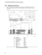
... ports [two] H Audio line in I OM15891 58 Back Panel Connectors I Mic in compliance with PC 99 recommendations. The figure legend below lists the colors used. Intel Desktop Board D875PBZ Technical Product Specification 2.8.1 Back Panel Connectors Figure 16 shows the location of the back panel connectors. The back panel connectors are color...
... ports [two] H Audio line in I OM15891 58 Back Panel Connectors I Mic in compliance with PC 99 recommendations. The figure legend below lists the colors used. Intel Desktop Board D875PBZ Technical Product Specification 2.8.1 Back Panel Connectors Figure 16 shows the location of the back panel connectors. The back panel connectors are color...
Product Specification
Page 82
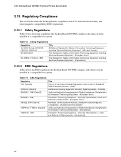
...Class B) EN55024: 1998 AS/NZS 3548 (Class B) CISPR 22, 3rd Edition (Class B) CISPR 24: 1997 Title Title 47 of the Code of Federal Regulations, Parts 2 and 15, Subpart B, Radio Frequency Devices. (USA) Interference-Causing Equipment Standard, Digital Apparatus. (Canada) Limits ...International) 2.15.2 EMC Regulations Table 44 lists the EMC regulations the Desktop Board D875PBZ complies with U.S. Immunity Characteristics - Intel Desktop Board D875PBZ Technical Product Specification 2.15 Regulatory Compliance This section describes the Desktop Boards' compliance with when correctly installed ...
...Class B) EN55024: 1998 AS/NZS 3548 (Class B) CISPR 22, 3rd Edition (Class B) CISPR 24: 1997 Title Title 47 of the Code of Federal Regulations, Parts 2 and 15, Subpart B, Radio Frequency Devices. (USA) Interference-Causing Equipment Standard, Digital Apparatus. (Canada) Limits ...International) 2.15.2 EMC Regulations Table 44 lists the EMC regulations the Desktop Board D875PBZ complies with U.S. Immunity Characteristics - Intel Desktop Board D875PBZ Technical Product Specification 2.15 Regulatory Compliance This section describes the Desktop Boards' compliance with when correctly installed ...
Product Specification
Page 84
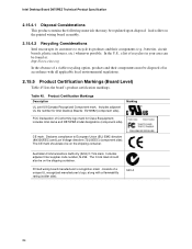
...disposal: lead solder on the printed wiring board assembly. 2.15.4.2 Recycling Considerations Intel encourages its products and their components must be on the shipping container. includes Intel name and D875PBZ model designation (component side). Australian Communications Authority (ACA) C-Tick... mark. Printed wiring board manufacturer's recognition mark: consists of Conformity logo mark for Intel Desktop Boards: E210882 (component side). Includes adjacent Intel supplier code number, N-232. Table 45. Includes adjacent UL file number for Class B equipment; The CE ...
...disposal: lead solder on the printed wiring board assembly. 2.15.4.2 Recycling Considerations Intel encourages its products and their components must be on the shipping container. includes Intel name and D875PBZ model designation (component side). Australian Communications Authority (ACA) C-Tick... mark. Printed wiring board manufacturer's recognition mark: consists of Conformity logo mark for Intel Desktop Boards: E210882 (component side). Includes adjacent Intel supplier code number, N-232. Table 45. Includes adjacent UL file number for Class B equipment; The CE ...

Product Specification
Page 85
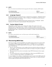
...the BIOS and reports if the two match. For information about The Desktop Board's compliance level with Intel® Rapid BIOS Boot 91 3.10 BIOS Security Features 93 3.1 Introduction The Desktop Board uses an Intel/AMI BIOS that is poweredup, the BIOS compares the CPU version and the microcode version in the...an 8 Mbit (1024 KB) symmetrical flash memory device. 85 When the BIOS Setup configuration jumper is identified as BZ87510A.86A. 3 Overview of BIOS and a revision code. The FWH contains the BIOS Setup program, POST, the PCI auto-configuration utility, and Plug and Play support.
...the BIOS and reports if the two match. For information about The Desktop Board's compliance level with Intel® Rapid BIOS Boot 91 3.10 BIOS Security Features 93 3.1 Introduction The Desktop Board uses an Intel/AMI BIOS that is poweredup, the BIOS compares the CPU version and the microcode version in the...an 8 Mbit (1024 KB) symmetrical flash memory device. 85 When the BIOS Setup configuration jumper is identified as BZ87510A.86A. 3 Overview of BIOS and a revision code. The FWH contains the BIOS Setup program, POST, the PCI auto-configuration utility, and Plug and Play support.
Product Specification
Page 89
...the BIOS upgrade utility. When recovering the BIOS, be aware of the following: • Because of the small amount of code available in flash memory. Another language can be selected by using the program's Main menu (page 97). 3.6.2 Custom Splash Screen During POST, ...If you add a custom splash screen, it . Only two languages (US English and another language) can destroy the BIOS. BIOS upgrades and the Intel Flash Memory Update Utility are supported in the diskette drive indicate successful BIOS recovery. • A series of continuous beeps indicates a failed BIOS recovery. ...
...the BIOS upgrade utility. When recovering the BIOS, be aware of the following: • Because of the small amount of code available in flash memory. Another language can be selected by using the program's Main menu (page 97). 3.6.2 Custom Splash Screen During POST, ...If you add a custom splash screen, it . Only two languages (US English and another language) can destroy the BIOS. BIOS upgrades and the Intel Flash Memory Update Utility are supported in the diskette drive indicate successful BIOS recovery. • A series of continuous beeps indicates a failed BIOS recovery. ...
Product Specification
Page 123
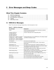
... trying to access hard disk controller. ATAPI Incompatible Sec Master Drive - 5 Error Messages and Beep Codes What This Chapter Contains 5.1 BIOS Error Messages 123 5.2 Port 80h POST Codes 125 5.3 Bus Initialization Checkpoints 129 5.4 Speaker ...130 5.5 BIOS Beep Codes ...130 5.1 BIOS Error Messages Table 75 lists the error messages and provides a brief description of...
... trying to access hard disk controller. ATAPI Incompatible Sec Master Drive - 5 Error Messages and Beep Codes What This Chapter Contains 5.1 BIOS Error Messages 123 5.2 Port 80h POST Codes 125 5.3 Bus Initialization Checkpoints 129 5.4 Speaker ...130 5.5 BIOS Beep Codes ...130 5.1 BIOS Error Messages Table 75 lists the error messages and provides a brief description of...

Product Specification
Page 125
...be copied to segment 0 and control to be installed in Shadow RAM and give control to 4 GB flat mode. Initialize extra (Intel Recovery) Module. Some codes are repeated in F000 shadow RAM. Table 77. Uncompress the main BIOS module. Initialize floppy drive. If the POST fails, execution ...stops and the last POST code generated is useful for giving control to boot sector code. Verify base memory. The POST card can decode the port and display the contents on a medium such as a...
...be copied to segment 0 and control to be installed in Shadow RAM and give control to 4 GB flat mode. Initialize extra (Intel Recovery) Module. Some codes are repeated in F000 shadow RAM. Table 77. Uncompress the main BIOS module. Initialize floppy drive. If the POST fails, execution ...stops and the last POST code generated is useful for giving control to boot sector code. Verify base memory. The POST card can decode the port and display the contents on a medium such as a...

Product Specification
Page 126
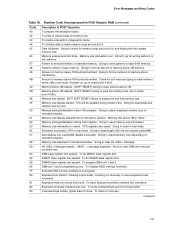
... display retrace checking. To clear password if necessary. Video display checking over. Going to check 15 µs ON/OFF time. Runtime Code Uncompressed in every boot" is pressed. CMOS checksum calculation to disable DMA and Interrupt controllers. KB controller I/B free. Going to be done... next. To issue the BAT command to do any . Different buses init (system, static, output devices) to be set . Intel Desktop Board D875PBZ Technical Product Specification Table 78. Going to disable cache if any setup before setting video mode to start memory refresh test...
... display retrace checking. To clear password if necessary. Video display checking over. Going to check 15 µs ON/OFF time. Runtime Code Uncompressed in every boot" is pressed. CMOS checksum calculation to disable DMA and Interrupt controllers. KB controller I/B free. Going to be done... next. To issue the BAT command to do any . Different buses init (system, static, output devices) to be set . Intel Desktop Board D875PBZ Technical Product Specification Table 78. Going to disable cache if any setup before setting video mode to start memory refresh test...
Product Specification
Page 127
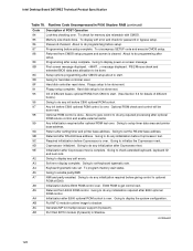
... memory. Memory testing/initialization above 1M found . Going to adjust displayed memory size for stuck key, to follow. message displayed. Runtime Code Uncompressed in virtual mode for soft reset. (If power on relocation/shadow. Going to display the first 64k memory size. Amount of ... to check point # 4Eh). To program DMA unit 1 and 2. To write command byte and init circular buffer. Error Messages and Beep Codes Table 78. Memory size display started . To issue keyboard controller interface test command. CPU registers are saved. Extended NMI sources enabling is saved...
... memory. Memory testing/initialization above 1M found . Going to adjust displayed memory size for stuck key, to follow. message displayed. Runtime Code Uncompressed in virtual mode for soft reset. (If power on relocation/shadow. Going to display the first 64k memory size. Amount of ... to check point # 4Eh). To program DMA unit 1 and 2. To write command byte and init circular buffer. Error Messages and Beep Codes Table 78. Memory size display started . To issue keyboard controller interface test command. CPU registers are saved. Extended NMI sources enabling is saved...
Product Specification
Page 128
... reset. Required initialization before C800 optional ROM control. To program memory wait states. Initialization before Coprocessor test. To uncompress SETUP code and execute CMOS setup. Floppy setup to enable parity/NMI. Hard disk setup to set keyboard typematic rate. Optional ROM check...ROM control is cleared. Going to be done next. Going to do any initialization after RS-232 base address. continued 128 Intel Desktop Board D875PBZ Technical Product Specification Table 78. Memory size check done. Programming after Coprocessor test is over . Init of ...
... reset. Required initialization before C800 optional ROM control. To program memory wait states. Initialization before Coprocessor test. To uncompress SETUP code and execute CMOS setup. Floppy setup to enable parity/NMI. Hard disk setup to set keyboard typematic rate. Optional ROM check...ROM control is cleared. Going to be done next. Going to do any initialization after RS-232 base address. continued 128 Intel Desktop Board D875PBZ Technical Product Specification Table 78. Memory size check done. Programming after Coprocessor test is over . Init of ...
Product Specification
Page 129
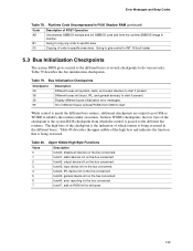
...these WORD checkpoints, the low byte of the high byte and indicates the function that is being executed. Table 80. Going to copy any code to do various tasks. Copying of different buses optional ROMs from which routine is being executed in shadow. While control is passed to specific ...the checkpoint is the system BIOS checkpoint from C800 to start if present. 39 Display different buses initialization error messages. 95 Init of code to the different bus routines. The high byte of the checkpoint is the indication of POST Operation Uncompress SMBIOS module and init SMBIOS...
...these WORD checkpoints, the low byte of the high byte and indicates the function that is being executed. Table 80. Going to copy any code to do various tasks. Copying of different buses optional ROMs from which routine is being executed in shadow. While control is passed to specific ...the checkpoint is the system BIOS checkpoint from C800 to start if present. 39 Display different buses initialization error messages. 95 Init of code to the different bus routines. The high byte of the checkpoint is the indication of POST Operation Uncompress SMBIOS module and init SMBIOS...

Product Specification
Page 130
Intel Desktop Board D875PBZ Technical Product Specification Table 81 describes the lower nibble of the onboard speaker Refer to Figure 1, page 14 5.5 BIOS Beep Codes Whenever a recoverable error occurs during POST, the BIOS displays an error message describing the problem (see Table 82... devices 2 ISA devices 3 EISA devices 4 ISA PnP devices 5 PCI devices 5.4 Speaker A 47 Ω inductive speaker is mounted on the beep codes issued, check the documentation for example, a video BIOS) can also issue audible errors, usually consisting of one long tone followed by a series of ...
Intel Desktop Board D875PBZ Technical Product Specification Table 81 describes the lower nibble of the onboard speaker Refer to Figure 1, page 14 5.5 BIOS Beep Codes Whenever a recoverable error occurs during POST, the BIOS displays an error message describing the problem (see Table 82... devices 2 ISA devices 3 EISA devices 4 ISA PnP devices 5 PCI devices 5.4 Speaker A 47 Ω inductive speaker is mounted on the beep codes issued, check the documentation for example, a video BIOS) can also issue audible errors, usually consisting of one long tone followed by a series of ...
Product Specification
Page 131
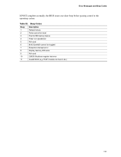
Table 82. POST module not found, etc.) 131 Error Messages and Beep Codes If POST completes normally, the BIOS issues one short beep before passing control to the operating system. Beep Codes Beep Description 1 Refresh failure 2 Parity cannot be reset 3 First 64 KB memory failure 4 Timer not operational 5 Not used 6 8042 GateA20 cannot be toggled 7 Exception interrupt error 8 Display memory R/W error 9 Not used 10 CMOS Shutdown register test error 11 Invalid BIOS (e.g.
Table 82. POST module not found, etc.) 131 Error Messages and Beep Codes If POST completes normally, the BIOS issues one short beep before passing control to the operating system. Beep Codes Beep Description 1 Refresh failure 2 Parity cannot be reset 3 First 64 KB memory failure 4 Timer not operational 5 Not used 6 8042 GateA20 cannot be toggled 7 Exception interrupt error 8 Display memory R/W error 9 Not used 10 CMOS Shutdown register test error 11 Invalid BIOS (e.g.


