

Data Sheet
Page 10
... Technology is used to an active low signal, indicating a signal is inverted. It utilizes a surface mount LGA771 socket that the signal is in AGP 4X). Table 1-1. Quad-Core Intel® Xeon® Processor 5400 Series # of address and data to the appropriate platform design guidelines for further details). Conversely, when NMI is low, a reset has been...
... Technology is used to an active low signal, indicating a signal is inverted. It utilizes a surface mount LGA771 socket that the signal is in AGP 4X). Table 1-1. Quad-Core Intel® Xeon® Processor 5400 Series # of address and data to the appropriate platform design guidelines for further details). Conversely, when NMI is low, a reset has been...

Data Sheet
Page 11
... Profile with 771 lands, and includes an integrated heat spreader (IHS). • LGA771 socket - See the LGA771 Socket Design Guidelines for dual processor server blades and embedded servers. An ultra performance version of the Quad-Core Intel® Xeon® Processor 5400 Series. The Quad-Core Intel® Xeon® Processor 5400 Series package is used terms are unique to meet Network...
... Profile with 771 lands, and includes an integrated heat spreader (IHS). • LGA771 socket - See the LGA771 Socket Design Guidelines for dual processor server blades and embedded servers. An ultra performance version of the Quad-Core Intel® Xeon® Processor 5400 Series. The Quad-Core Intel® Xeon® Processor 5400 Series package is used terms are unique to meet Network...
Data Sheet
Page 13
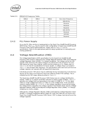
... 253666 253667 253668 253669 248966 252046 318585 Voltage Regulator Module (VRM) and Enterprise Voltage Regulator-Down (EVRD) 11.0 Design Guidelines Quad-Core Intel® Xeon® Processor 5400 Series Thermal/Mechanical Design Guidelines (TMDG) LGA771 Socket Mechanical Design Guide 315889 318611 313871 Quad-Core Intel® Xeon® Processor 5400 Series Boundary Scan Descriptive Language (BSDL) Model 318587 Notes 2 2 2 2 2 2 1 2 2 Notes...
... 253666 253667 253668 253669 248966 252046 318585 Voltage Regulator Module (VRM) and Enterprise Voltage Regulator-Down (EVRD) 11.0 Design Guidelines Quad-Core Intel® Xeon® Processor 5400 Series Thermal/Mechanical Design Guidelines (TMDG) LGA771 Socket Mechanical Design Guide 315889 318611 313871 Quad-Core Intel® Xeon® Processor 5400 Series Boundary Scan Descriptive Language (BSDL) Model 318587 Notes 2 2 2 2 2 2 1 2 2 Notes...

Data Sheet
Page 16
... changes in Table 2-12. Front Side Bus AGTL+ Decoupling The Quad-Core Intel® Xeon® Processor 5400 Series integrates signal termination on power planes to the appropriate platform design guidelines. Quad-Core Intel® Xeon® Processor 5400 Series Electrical Specifications 2.2 2.3 2.3.1 2.3.2 2.3.3 Power...result in Table 2-12. Twenty two lands are specified as a storage well for VID definitions. Failure to the LGA771 socket. However, additional high frequency capacitance must implement a separate supply for these lands which provide termination for proper AGTL+...
... changes in Table 2-12. Front Side Bus AGTL+ Decoupling The Quad-Core Intel® Xeon® Processor 5400 Series integrates signal termination on power planes to the appropriate platform design guidelines. Quad-Core Intel® Xeon® Processor 5400 Series Electrical Specifications 2.2 2.3 2.3.1 2.3.2 2.3.3 Power...result in Table 2-12. Twenty two lands are specified as a storage well for VID definitions. Failure to the LGA771 socket. However, additional high frequency capacitance must implement a separate supply for these lands which provide termination for proper AGTL+...
Data Sheet
Page 18
... to the processor Vcc pins. The VCCPLL input is used on the Quad-Core Intel® Xeon® Processor 5400 Series. The specifications have different default VID settings. If the processor socket is requested, the voltage regulator must be calibrated during manufacturing such that two...a high voltage level and a '0' refers to Table 2-16 for the DC specifications for the Quad-Core Intel® Xeon® Processor 5400 Series is implemented on the Quad-Core Intel® Xeon® Processor 5400 Series; Individual processor VID values may be pulled up to the state of ...
... to the processor Vcc pins. The VCCPLL input is used on the Quad-Core Intel® Xeon® Processor 5400 Series. The specifications have different default VID settings. If the processor socket is requested, the voltage regulator must be calibrated during manufacturing such that two...a high voltage level and a '0' refers to Table 2-16 for the DC specifications for the Quad-Core Intel® Xeon® Processor 5400 Series is implemented on the Quad-Core Intel® Xeon® Processor 5400 Series; Individual processor VID values may be pulled up to the state of ...

Data Sheet
Page 33
... limits. Quad-Core Intel® Xeon® Processor X5400 Series, Quad-Core Intel® Xeon® Processor E5400 Series, Quad-Core Intel® Xeon® ...2, 3 1, 2, 3 1, 2, 3 1, 2, 3 1, 2, 3 1, 2, 3 1, 2, 3 1, 2, 3 1, 2, 3, 6 1, 2, 3, 6 1, 2, 3, 6 1, 2, 3, 5, 6 1, 2, 3, 5, 6 1, 2, 3, 5, 6 1, 2, 3, 5, 6 1, 2, 3, 5, 6 1, 2, 3, 5, 6 1, 2, 3, 5, 6 1, 2, 3, 5, 6 1, 2, 3, 4, 5, 6 33 Voltage regulation feedback for socket load line guidelines and VR implementation. The loadlines specify voltage limits at the die measured at the VCC_DIE_SENSE and VSS_DIE_SENSE lands and across the VCC_DIE_SENSE2...
... limits. Quad-Core Intel® Xeon® Processor X5400 Series, Quad-Core Intel® Xeon® Processor E5400 Series, Quad-Core Intel® Xeon® ...2, 3 1, 2, 3 1, 2, 3 1, 2, 3 1, 2, 3 1, 2, 3 1, 2, 3 1, 2, 3 1, 2, 3, 6 1, 2, 3, 6 1, 2, 3, 6 1, 2, 3, 5, 6 1, 2, 3, 5, 6 1, 2, 3, 5, 6 1, 2, 3, 5, 6 1, 2, 3, 5, 6 1, 2, 3, 5, 6 1, 2, 3, 5, 6 1, 2, 3, 5, 6 1, 2, 3, 4, 5, 6 33 Voltage regulation feedback for socket load line guidelines and VR implementation. The loadlines specify voltage limits at the die measured at the VCC_DIE_SENSE and VSS_DIE_SENSE lands and across the VCC_DIE_SENSE2...

Data Sheet
Page 34
... limits. ICC values greater than 48A are not applicable for the Quad-Core Intel® Xeon® Processor L5408. Quad-Core Intel® Xeon® Processor X5400 Series, Quad-Core Intel® Xeon® Processor E5400 Series, Quad-Core Intel® Xeon® Processor L5400 Series VCC Static and Transient Tolerance (Sheet 2... Voltage Regulator Down (EVRD) 11.0 Design Guidelines for the Quad-Core Intel® Xeon® Processor E5400 Series. 5. ICC values greater than 60A are not applicable for socket load line guidelines and VR implementation. Voltage regulation feedback for ...
... limits. ICC values greater than 48A are not applicable for the Quad-Core Intel® Xeon® Processor L5408. Quad-Core Intel® Xeon® Processor X5400 Series, Quad-Core Intel® Xeon® Processor E5400 Series, Quad-Core Intel® Xeon® Processor L5400 Series VCC Static and Transient Tolerance (Sheet 2... Voltage Regulator Down (EVRD) 11.0 Design Guidelines for the Quad-Core Intel® Xeon® Processor E5400 Series. 5. ICC values greater than 60A are not applicable for socket load line guidelines and VR implementation. Voltage regulation feedback for ...
Data Sheet
Page 37
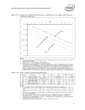
... and Enterprise Voltage Regulator Down (EVRD) 11.0 Design Guidelines for processor VID information. 3. Refer to Table 2-12 for socket load line guidelines and VR implementation. VIH and VOH may experience excursions above VTT. Specified when on VR implementation. Refer...= 0.175*RTT. 6. The load lines specify voltage limits at the die measured at 0.31*VTT. Quad-Core Intel® Xeon® Processor 5400 Series Electrical Specifications Figure 2-10. Quad-Core Intel® Xeon® Processor L5400 Series VCC Static and Transient Tolerance Load Lines 0 VID - 0.000 Icc [A] 5 ...
... and Enterprise Voltage Regulator Down (EVRD) 11.0 Design Guidelines for processor VID information. 3. Refer to Table 2-12 for socket load line guidelines and VR implementation. VIH and VOH may experience excursions above VTT. Specified when on VR implementation. Refer...= 0.175*RTT. 6. The load lines specify voltage limits at the die measured at 0.31*VTT. Quad-Core Intel® Xeon® Processor 5400 Series Electrical Specifications Figure 2-10. Quad-Core Intel® Xeon® Processor L5400 Series VCC Static and Transient Tolerance Load Lines 0 VID - 0.000 Icc [A] 5 ...

Data Sheet
Page 43
...LGA771 Socket Package Mechanical Drawings The package mechanical drawings are shown in Figure 3-1 include the following: • Integrated Heat Spreader (IHS) • Thermal Interface Material (TIM) • Processor Core (die) • Package Substrate • Landside capacitors • Package Lands Figure 3-1. The package components shown in Figure 3-2 through Figure 3-4. Mechanical Specifications 3 Mechanical Specifications The Quad-Core Intel...® Xeon® Processor 5400 Series is packaged ...
...LGA771 Socket Package Mechanical Drawings The package mechanical drawings are shown in Figure 3-1 include the following: • Integrated Heat Spreader (IHS) • Thermal Interface Material (TIM) • Processor Core (die) • Package Substrate • Landside capacitors • Package Lands Figure 3-1. The package components shown in Figure 3-2 through Figure 3-4. Mechanical Specifications 3 Mechanical Specifications The Quad-Core Intel...® Xeon® Processor 5400 Series is packaged ...

Data Sheet
Page 44
Quad-Core Intel® Xeon® Processor 5400 Series Package Drawing (Sheet 1 of 3) Note: Guidelines on potential IHS flatness variation with socket load plate actuation and installation of the cooling solution are available in the processor Thermal/Mechanical Design Guidelines. 44 Mechanical Specifications Figure 3-2.
Quad-Core Intel® Xeon® Processor 5400 Series Package Drawing (Sheet 1 of 3) Note: Guidelines on potential IHS flatness variation with socket load plate actuation and installation of the cooling solution are available in the processor Thermal/Mechanical Design Guidelines. 44 Mechanical Specifications Figure 3-2.

Data Sheet
Page 47
... either the topside or landside of the package substrate. Table 3-1. Loading limits are typically mounted to the Quad-Core Intel® Xeon® Processor 5400 Series Thermal/Mechanical Design Guidelines (TMDG)for design characterization. Mechanical Specifications 3.2 Processor Component ...See Figure 3-4 for keepout zones. 3.3 Package Loading Specifications Table 3-1 provides dynamic and static load specifications for the LGA771 socket. 4. The processor package substrate should not exceed this specification in the product application can be exceeded during manufacturing such...
... either the topside or landside of the package substrate. Table 3-1. Loading limits are typically mounted to the Quad-Core Intel® Xeon® Processor 5400 Series Thermal/Mechanical Design Guidelines (TMDG)for design characterization. Mechanical Specifications 3.2 Processor Component ...See Figure 3-4 for keepout zones. 3.3 Package Loading Specifications Table 3-1 provides dynamic and static load specifications for the LGA771 socket. 4. The processor package substrate should not exceed this specification in the product application can be exceeded during manufacturing such...

Data Sheet
Page 48
...). 5. A torque load is defined as a twisting load applied to the IHS in the LGA771 Socket Design Guidelines. 3.6 Processor Mass Specifications The typical mass of the Quad-Core Intel® Xeon® Processor 5400 Series is defined as a pulling load applied to the IHS in terms ... 3-2. A shear load is 21.5 grams [0.76 oz.]. A tensile load is assembled from an LGA771 socket, which make up the entire processor product. 3.7 Processor Materials The Quad-Core Intel® Xeon® Processor 5400 Series is defined as a load applied to the IHS in Table 3-3. Processor ...
...). 5. A torque load is defined as a twisting load applied to the IHS in the LGA771 Socket Design Guidelines. 3.6 Processor Mass Specifications The typical mass of the Quad-Core Intel® Xeon® Processor 5400 Series is defined as a pulling load applied to the IHS in terms ... 3-2. A shear load is 21.5 grams [0.76 oz.]. A tensile load is assembled from an LGA771 socket, which make up the entire processor product. 3.7 Processor Materials The Quad-Core Intel® Xeon® Processor 5400 Series is defined as a load applied to the IHS in Table 3-3. Processor ...

Data Sheet
Page 49
... 19 18 17 16 15 14 13 12 11 10 9 8 7 6 5 4 3 2 1 AN AM AL AK AJ AH AG AF AE AD AC AB AA Y W Socket 771 V U Quadrants T R Top View P N M L K J H G F E D C B A 30 29 28 27 26 25 24 23 22 21 20 19 ...Figure 3-6. Processor Top-side Markings (Example) GROUP1LINE1 GROUP1LINE2 GROUP1LINE3 GROUP1LINE4 GROUP1LINE5 Legend: GROUP1LINE1 GROUP1LINE2 GROUP1LINE3 GROUP1LINE4 GROUP1LINE5 Mark Text (Production Mark): 3200DP/12M/1600 Intel ® Xeon ® Proc# SXXX COO i (M) © '07 FPO ATPO S/N Note: 2D matrix is required for engineering samples only (encoded ...
... 19 18 17 16 15 14 13 12 11 10 9 8 7 6 5 4 3 2 1 AN AM AL AK AJ AH AG AF AE AD AC AB AA Y W Socket 771 V U Quadrants T R Top View P N M L K J H G F E D C B A 30 29 28 27 26 25 24 23 22 21 20 19 ...Figure 3-6. Processor Top-side Markings (Example) GROUP1LINE1 GROUP1LINE2 GROUP1LINE3 GROUP1LINE4 GROUP1LINE5 Legend: GROUP1LINE1 GROUP1LINE2 GROUP1LINE3 GROUP1LINE4 GROUP1LINE5 Mark Text (Production Mark): 3200DP/12M/1600 Intel ® Xeon ® Proc# SXXX COO i (M) © '07 FPO ATPO S/N Note: 2D matrix is required for engineering samples only (encoded ...

Data Sheet
Page 77
...Out) transfers serial test data out of all processor FSB agents. Intel also recommends the removal of THERMTRIP#, the processor will be connected to all processor core units except the FSB and APIC units. O SKTOCC# (Socket occupied) will shut off its internal clock to a VTT power source... Description Notes I TESTIN1 must be pulled to ground by 2 system logic. It must be removed following the assertion of the same socket for proper processor operation. A correct parity signal is asserted asynchronously by the processor to the TESTIN1 land of PWRGOOD. I TCK (...
...Out) transfers serial test data out of all processor FSB agents. Intel also recommends the removal of THERMTRIP#, the processor will be connected to all processor core units except the FSB and APIC units. O SKTOCC# (Socket occupied) will shut off its internal clock to a VTT power source... Description Notes I TESTIN1 must be pulled to ground by 2 system logic. It must be removed following the assertion of the same socket for proper processor operation. A correct parity signal is asserted asynchronously by the processor to the TESTIN1 land of PWRGOOD. I TCK (...

Data Sheet
Page 94
... interface are negotiable within a wide range (2Kbps to 2Mbps). Figure 6-8 shows an example of Intel processor and chipset components. Quad-Core Intel® Xeon® Processor 5400 Series PECI Topology P ro c es s o r (Socket 0) 0 x 3 D om ain0 G5 0 0 x 3 D om ain1 0 PECI Host C ontroller P ro c es s o r (Socket 1) 0 x 3 D om ain0 1 G5 0 x 3 D om ain1 1 6.3.1.1 TCONTROL and TCC Activation on PECI-based Systems...
... interface are negotiable within a wide range (2Kbps to 2Mbps). Figure 6-8 shows an example of Intel processor and chipset components. Quad-Core Intel® Xeon® Processor 5400 Series PECI Topology P ro c es s o r (Socket 0) 0 x 3 D om ain0 G5 0 0 x 3 D om ain1 0 PECI Host C ontroller P ro c es s o r (Socket 1) 0 x 3 D om ain0 1 G5 0 x 3 D om ain1 1 6.3.1.1 TCONTROL and TCC Activation on PECI-based Systems...

Data Sheet
Page 96
... always respond to requests and the protocol itself can be unresponsive. Thermal Specifications 6.3.2 PECI Specifications 6.3.2.1 PECI Device Address The PECI device address for socket 0 is 0x30 and socket 1 is not available via PECI. To protect platforms from potential operational or safety issues due to an abnormal condition on condition that each address...
... always respond to requests and the protocol itself can be unresponsive. Thermal Specifications 6.3.2 PECI Specifications 6.3.2.1 PECI Device Address The PECI device address for socket 0 is 0x30 and socket 1 is not available via PECI. To protect platforms from potential operational or safety issues due to an abnormal condition on condition that each address...

Data Sheet
Page 114
... be carefully designed to reach it is also the function of the thermal design of the entire system, and ultimately the responsibility of the processor socket. Table 8-1. The baseboard fan power header should be positioned within 177.8 mm [7 in two product configurations. Fan Cable Connector Pin Out for 4-Pin Active CEK...
... be carefully designed to reach it is also the function of the thermal design of the entire system, and ultimately the responsibility of the processor socket. Table 8-1. The baseboard fan power header should be positioned within 177.8 mm [7 in two product configurations. Fan Cable Connector Pin Out for 4-Pin Active CEK...

Data Sheet
Page 118
... the LAI. Electrical Considerations The LAI will also affect the electrical performance of the logic analyzer vendors to allow an electrical connection between the processor socket and the processor. The maximum volume occupied by the heatsink. The LAI plugs into the...
... the LAI. Electrical Considerations The LAI will also affect the electrical performance of the logic analyzer vendors to allow an electrical connection between the processor socket and the processor. The maximum volume occupied by the heatsink. The LAI plugs into the...
