
Technical Product Specification
Page 2
... or otherwise, to deviate from future changes to only the standard Intel® Desktop Board DZ87KLT-75K with BIOS identifier KLZ8711D.86A. INFORMATION IN THIS DOCUMENT IS PROVIDED IN CONNECTION WITH INTEL® PRODUCTS. may not be claimed as errata, which may ... of documents and other intellectual property rights. Copyright 2013, Intel Corporation. Revision History Revision 001 Revision History Date First release of the Intel® Desktop Board DZ87KLT-75K Technical Product May 2013 Specification This product specification applies to them. UNLESS...
... or otherwise, to deviate from future changes to only the standard Intel® Desktop Board DZ87KLT-75K with BIOS identifier KLZ8711D.86A. INFORMATION IN THIS DOCUMENT IS PROVIDED IN CONNECTION WITH INTEL® PRODUCTS. may not be claimed as errata, which may ... of documents and other intellectual property rights. Copyright 2013, Intel Corporation. Revision History Revision 001 Revision History Date First release of the Intel® Desktop Board DZ87KLT-75K Technical Product May 2013 Specification This product specification applies to them. UNLESS...
Technical Product Specification
Page 3
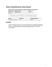
... Basic Desktop Board DZ87KLT-75K Identification Information AA Revision BIOS Revision Notes G74721-003 KLZ8711D.86A 1,2 Notes: 1. iii See http://www.intel.com/content/www/us/en/motherboards/desktopmotherboards/motherboards.html?wapkw=desktop+boards for the latest documentation. The Z87 chipset used on the component side of the following component: Device Intel Z87 Express Chipset...
... Basic Desktop Board DZ87KLT-75K Identification Information AA Revision BIOS Revision Notes G74721-003 KLZ8711D.86A 1,2 Notes: 1. iii See http://www.intel.com/content/www/us/en/motherboards/desktopmotherboards/motherboards.html?wapkw=desktop+boards for the latest documentation. The Z87 chipset used on the component side of the following component: Device Intel Z87 Express Chipset...

Technical Product Specification
Page 5
... TPS is specifically not intended for the Intel® Desktop Board DZ87KLT-75K. What This Document Contains Chapter 1 2 3 4 5 Description A description of the hardware used on the Intel Desktop Board DZ87KLT-75K A map of the resources of the Intel Desktop Board The features supported by the BIOS Setup program A description of the BIOS error messages, beep codes, and POST codes...
... TPS is specifically not intended for the Intel® Desktop Board DZ87KLT-75K. What This Document Contains Chapter 1 2 3 4 5 Description A description of the hardware used on the Intel Desktop Board DZ87KLT-75K A map of the resources of the Intel Desktop Board The features supported by the BIOS Setup program A description of the BIOS error messages, beep codes, and POST codes...
Technical Product Specification
Page 8
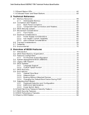
Intel Desktop Board DZ87KLT-75K Technical Product Specification 1.13 Board Status LEDs 46 1.14 Onboard Power and Reset Buttons 48 2 Technical Reference 2.1 Memory Resources 49 2.1.1 Addressable Memory 49 2.2 Connectors and Headers 50 2.2.1 Back Panel Connectors 51 2.2.2 Component-side Connectors and Headers 52 2.3 BIOS Security Jumper 63 2.4 Mechanical Considerations 65 2.4.1 Form Factor 65 2.5 Electrical Considerations 66...
Intel Desktop Board DZ87KLT-75K Technical Product Specification 1.13 Board Status LEDs 46 1.14 Onboard Power and Reset Buttons 48 2 Technical Reference 2.1 Memory Resources 49 2.1.1 Addressable Memory 49 2.2 Connectors and Headers 50 2.2.1 Back Panel Connectors 51 2.2.2 Component-side Connectors and Headers 52 2.3 BIOS Security Jumper 63 2.4 Mechanical Considerations 65 2.4.1 Form Factor 65 2.5 Electrical Considerations 66...
Technical Product Specification
Page 9
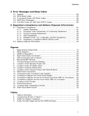
... Feature Summary 11 2. Major Board Components 13 2. Contents 4 Error Messages and Beep Codes 4.1 Speaker 83 4.2 BIOS Beep Codes 83 4.3 Front-panel Power LED Blink Codes 84 4.4 BIOS Error Messages 84 4.5 Port 80h Power On Self Test (POST) Codes 85 5 Regulatory Compliance and Battery Disposal ...91 5.1.2 European Union Declaration of the Jumper 63 18. LAN Connectors LED Locations 32 6. Component-side Connectors and Headers 52 14. Intel Visual BIOS Screen 72 Tables 1. Location of the Onboard Power and Reset Buttons 48 12. Location of the Standby Power LED 44 9. Block ...
... Feature Summary 11 2. Major Board Components 13 2. Contents 4 Error Messages and Beep Codes 4.1 Speaker 83 4.2 BIOS Beep Codes 83 4.3 Front-panel Power LED Blink Codes 84 4.4 BIOS Error Messages 84 4.5 Port 80h Power On Self Test (POST) Codes 85 5 Regulatory Compliance and Battery Disposal ...91 5.1.2 European Union Declaration of the Jumper 63 18. LAN Connectors LED Locations 32 6. Component-side Connectors and Headers 52 14. Intel Visual BIOS Screen 72 Tables 1. Location of the Onboard Power and Reset Buttons 48 12. Location of the Standby Power LED 44 9. Block ...
Technical Product Specification
Page 10
Intel Desktop Board DZ87KLT-75K Technical Product Specification 5. Supported Memory Configurations 22 6. Effects of Pressing the Power Switch 37 9. Power States and Targeted System Power 38 10. Board Status LEDs 47 12. Front Panel Audio Header for a One-Color Power LED 61 29. States for Intel... LED States 32 8. Dual-Port Front Panel USB 2.0 Headers 55 19. Front Panel CIR Receiver (Input) Header 56 23. BIOS Setup Security Jumper Settings 64 31. Processor, Front and Rear Chassis, and Auxiliary (4-Pin) Fan Headers ..... 56 22. Environmental Specifications...
Intel Desktop Board DZ87KLT-75K Technical Product Specification 5. Supported Memory Configurations 22 6. Effects of Pressing the Power Switch 37 9. Power States and Targeted System Power 38 10. Board Status LEDs 47 12. Front Panel Audio Header for a One-Color Power LED 61 29. States for Intel... LED States 32 8. Dual-Port Front Panel USB 2.0 Headers 55 19. Front Panel CIR Receiver (Input) Header 56 23. BIOS Setup Security Jumper Settings 64 31. Processor, Front and Rear Chassis, and Auxiliary (4-Pin) Fan Headers ..... 56 22. Environmental Specifications...
Technical Product Specification
Page 12
...connector (blue) • Separate module that provides both Bluetooth* and WiFi included with the desktop board Intel® Visual BIOS Note: Only Bluethooth v2.1 is supported • Intel® BIOS resident in SPI Flash device • Support for Advanced Configuration and Power Interface (ACPI), Plug and Play... Fan speed control using voltage control (4-pin fan headers front, rear, and auxiliary) with selectable support in BIOS for 3-wire fans • Support for Platform Environmental Control Interface (PECI) 12 Intel Desktop Board DZ87KLT-75K Technical Product Specification Table 1.
...connector (blue) • Separate module that provides both Bluetooth* and WiFi included with the desktop board Intel® Visual BIOS Note: Only Bluethooth v2.1 is supported • Intel® BIOS resident in SPI Flash device • Support for Advanced Configuration and Power Interface (ACPI), Plug and Play... Fan speed control using voltage control (4-pin fan headers front, rear, and auxiliary) with selectable support in BIOS for 3-wire fans • Support for Platform Environmental Control Interface (PECI) 12 Intel Desktop Board DZ87KLT-75K Technical Product Specification Table 1.

Technical Product Specification
Page 14
... chassis fan header 2 V Onboard power button W Onboard reset button X Piezoelectric speaker Y Main power connector (2 x 12) Z Standby power LED AA Front panel USB 3.0 connector BB BIOS security jumper CC Chassis intrusion header DD SATA 6.0 Gb/s connectors through the PCH (blue) EE SATA 6.0 Gb/s connectors through a Marvel 88SE9172 controller (gray) FF PCI...Front panel connector JJ Power On Self Test (POST) LED display KK POST LED display LL Front panel USB 2.0 connector (black) continued 14 Intel Desktop Board DZ87KLT-75K Technical Product Specification Table 2.
... chassis fan header 2 V Onboard power button W Onboard reset button X Piezoelectric speaker Y Main power connector (2 x 12) Z Standby power LED AA Front panel USB 3.0 connector BB BIOS security jumper CC Chassis intrusion header DD SATA 6.0 Gb/s connectors through the PCH (blue) EE SATA 6.0 Gb/s connectors through a Marvel 88SE9172 controller (gray) FF PCI...Front panel connector JJ Power On Self Test (POST) LED display KK POST LED display LL Front panel USB 2.0 connector (black) continued 14 Intel Desktop Board DZ87KLT-75K Technical Product Specification Table 2.

Technical Product Specification
Page 17
...-to Section 2.5.1 on page 66 for the Intel http://ark.intel.com Desktop Board DZ87KLT-75K Supported processors Chipset information BIOS and driver updates Tested memory Integration information http://processormatch.intel.com https://wwwssl.intel.com/content/www/us/en/chipsets/performancechipsets/chipsets.html http://downloadcenter.intel.com http://www.intel.com/support/motherboards/desktop/sb/CS025414.htm http...
...-to Section 2.5.1 on page 66 for the Intel http://ark.intel.com Desktop Board DZ87KLT-75K Supported processors Chipset information BIOS and driver updates Tested memory Integration information http://processormatch.intel.com https://wwwssl.intel.com/content/www/us/en/chipsets/performancechipsets/chipsets.html http://downloadcenter.intel.com http://www.intel.com/support/motherboards/desktop/sb/CS025414.htm http...
Technical Product Specification
Page 19
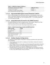
... driver software): • Single Display is a mode with one display port activated to display the output to one display device. • Intel® Display Clone is a mode with up to three display ports activated to drive the content with up to three display ports activated to... HDMI Port Status Conditions PCI Express x16 Connector Status No add-in card installed PCI Express x16 add-in card installed Note: May require BIOS setup menu changes. The PCH supports HDCP 1.4 for protecting high definition content against unauthorized copy or interception between a source (computer, digital ...
... driver software): • Single Display is a mode with one display port activated to display the output to one display device. • Intel® Display Clone is a mode with up to three display ports activated to drive the content with up to three display ports activated to... HDMI Port Status Conditions PCI Express x16 Connector Status No add-in card installed PCI Express x16 add-in card installed Note: May require BIOS setup menu changes. The PCH supports HDCP 1.4 for protecting high definition content against unauthorized copy or interception between a source (computer, digital ...
Technical Product Specification
Page 21
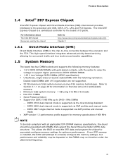
...mode is a centralized controller for optimum performance. Product Description 1.4 Intel® Z87 Express Chipset Intel Z87 Express Chipset with DIMMs that support the Serial Presence Detect (SPD) data structure. This allows the BIOS to read the SPD data and program the chipset to support ... be populated with Direct Media Interface (DMI) interconnect provides interfaces to -chip connection between the processor and the PCH. The Intel Z87 Express Chipset is supported via XMP profiles and manual mode • XMP version 1.3 performance profile support for concurrent traffic...
...mode is a centralized controller for optimum performance. Product Description 1.4 Intel® Z87 Express Chipset Intel Z87 Express Chipset with DIMMs that support the Serial Presence Detect (SPD) data structure. This allows the BIOS to read the SPD data and program the chipset to support ... be populated with Direct Media Interface (DMI) interconnect provides interfaces to -chip connection between the processor and the PCH. The Intel Z87 Express Chipset is supported via XMP profiles and manual mode • XMP version 1.3 performance profile support for concurrent traffic...
Technical Product Specification
Page 22
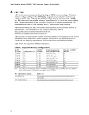
... double-sided memory modules (containing two rows of SDRAM) and "SS" refers to http://www.intel.com/support/processors/sb/CS020033.htm?wapkw=(processor+warranty). Intel Desktop Board DZ87KLT-75K Technical Product Specification CAUTION 1.5 V is the recommended and default setting for performance tuning purposes only...Intel has not tested and does not warranty the operation of SDRAM). Table 5. For information about... Tested Memory XMP Tested Memory Refer to fail; (iii) cause reductions in system performance; (iv) cause additional heat or other memory voltage settings in the BIOS...
... double-sided memory modules (containing two rows of SDRAM) and "SS" refers to http://www.intel.com/support/processors/sb/CS020033.htm?wapkw=(processor+warranty). Intel Desktop Board DZ87KLT-75K Technical Product Specification CAUTION 1.5 V is the recommended and default setting for performance tuning purposes only...Intel has not tested and does not warranty the operation of SDRAM). Table 5. For information about... Tested Memory XMP Tested Memory Refer to fail; (iii) cause reductions in system performance; (iv) cause additional heat or other memory voltage settings in the BIOS...
Technical Product Specification
Page 26
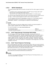
Intel Desktop Board DZ87KLT-75K Technical Product Specification 1.5.3 SATA Interfaces The board provides eight SATA connectors, through the PCH, which support one device each: • Six SATA 6.0 Gb/s interfaces through the Intel Z87 Express Chipset with Intel® Rapid Storage Technology RAID support (blue) • Two SATA...SMART alerting, and RAID 0 auto replace. NOTE Many SATA drives use supported RAID and Intel Smart Response Technology features, you must first enable RAID in the BIOS. 26 It allows configuration of a computer system with system performance at or near SSD ...
Intel Desktop Board DZ87KLT-75K Technical Product Specification 1.5.3 SATA Interfaces The board provides eight SATA connectors, through the PCH, which support one device each: • Six SATA 6.0 Gb/s interfaces through the Intel Z87 Express Chipset with Intel® Rapid Storage Technology RAID support (blue) • Two SATA...SMART alerting, and RAID 0 auto replace. NOTE Many SATA drives use supported RAID and Intel Smart Response Technology features, you must first enable RAID in the BIOS. 26 It allows configuration of a computer system with system performance at or near SSD ...
Technical Product Specification
Page 27
... to ± 13 minutes/year at 25 ºC with an equivalent one. When the voltage drops below a certain level, the BIOS Setup program settings stored in , the standby current from the power supply extends the life of three years. When the computer is plugged... serialized IRQ support for PCI systems • Intelligent power management, including a programmable wake-up event interface • PCI power management support The BIOS Setup program provides configuration options for example, the date and time) might not be notified during POST. Product Description 1.6 Real-Time Clock Subsystem ...
... to ± 13 minutes/year at 25 ºC with an equivalent one. When the voltage drops below a certain level, the BIOS Setup program settings stored in , the standby current from the power supply extends the life of three years. When the computer is plugged... serialized IRQ support for PCI systems • Intelligent power management, including a programmable wake-up event interface • PCI power management support The BIOS Setup program provides configuration options for example, the date and time) might not be notified during POST. Product Description 1.6 Real-Time Clock Subsystem ...
Technical Product Specification
Page 40
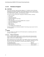
...of standby current required depends on or off the system power through system control. When resuming from the +5 V standby line. Intel Desktop Board DZ87KLT-75K Technical Product Specification 1.12.2 Hardware Support CAUTION Ensure that provides full ACPI support. 1.12.2.1 Power Connector ATX12V-compliant power supplies can... Available PC technology require power from an AC power failure, the computer returns to the power state it was in the BIOS Setup program's Boot menu. When an ACPI-enabled system receives the correct command, the power supply removes all non-standby voltages...
...of standby current required depends on or off the system power through system control. When resuming from the +5 V standby line. Intel Desktop Board DZ87KLT-75K Technical Product Specification 1.12.2 Hardware Support CAUTION Ensure that provides full ACPI support. 1.12.2.1 Power Connector ATX12V-compliant power supplies can... Available PC technology require power from an AC power failure, the computer returns to the power state it was in the BIOS Setup program's Boot menu. When an ACPI-enabled system receives the correct command, the power supply removes all non-standby voltages...

Technical Product Specification
Page 42
...Express add-in boards that can damage the power supply. Table 10 on PME enabled in power management and can participate in the BIOS). 1.12.2.7 WAKE# Signal Wake-up device or event, the system quickly returns to wake the computer. Failure to enter the ACPI...enables the board to provide adequate standby current when implementing Instantly Available PC technology can wake the computer from the S3 state. Intel Desktop Board DZ87KLT-75K Technical Product Specification 1.12.2.4 Instantly Available PC Technology CAUTION For Instantly Available PC technology, the +5 V standby line for ...
...Express add-in boards that can damage the power supply. Table 10 on PME enabled in power management and can participate in the BIOS). 1.12.2.7 WAKE# Signal Wake-up device or event, the system quickly returns to wake the computer. Failure to enter the ACPI...enables the board to provide adequate standby current when implementing Instantly Available PC technology can wake the computer from the S3 state. Intel Desktop Board DZ87KLT-75K Technical Product Specification 1.12.2.4 Instantly Available PC Technology CAUTION For Instantly Available PC technology, the +5 V standby line for ...
Technical Product Specification
Page 43
... computer appears to do so could damage the board and any attached devices. 43 Failure to be added to the BIOS Event Log for each event that takes place until the BIOS Event Log is cleared. 1.12.2.11 +5 V Standby Power Indicator LED The +5 V standby power indicator LED shows that the power supply...
... computer appears to do so could damage the board and any attached devices. 43 Failure to be added to the BIOS Event Log for each event that takes place until the BIOS Event Log is cleared. 1.12.2.11 +5 V Standby Power Indicator LED The +5 V standby power indicator LED shows that the power supply...
Technical Product Specification
Page 46
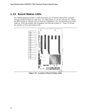
Once the activity has completed, the LED will remain on , all the LEDs are off. Figure 10 shows the location of Board Status LEDs 46 Location of the board status LEDs. At initial power on . When the BIOS starts an activity such as memory initialization, the corresponding LED starts flashing. Figure 10. Intel Desktop Board DZ87KLT-75K Technical Product Specification 1.13 Board Status LEDs The Desktop Board provides 11 LEDs that allow you to monitor the board's progress through the BIOS Power-on Self-Test.
Once the activity has completed, the LED will remain on , all the LEDs are off. Figure 10 shows the location of Board Status LEDs 46 Location of the board status LEDs. At initial power on . When the BIOS starts an activity such as memory initialization, the corresponding LED starts flashing. Figure 10. Intel Desktop Board DZ87KLT-75K Technical Product Specification 1.13 Board Status LEDs The Desktop Board provides 11 LEDs that allow you to monitor the board's progress through the BIOS Power-on Self-Test.
Technical Product Specification
Page 47
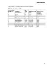
... 10 LED Name A Hard Drive Activity LED Color Blue B CPU Hot Red C VR Hot Red D Watch Dog Fire / Back to Red BIOS E CPU Initialization Green F Memory Initialization Green G Video Initialization Green H USB Initialization Green I Hard Drive Initialization Green J Option ROM Initialization Green .../Flash Control Source Hard drive controller(s) Discrete circuit Discrete circuit BIOS On/Off/Flash On/Off/Flash On/Off/Flash On/Off/Flash On/Off/Flash On/Off/Flash On/Off/Flash BIOS BIOS BIOS BIOS BIOS BIOS BIOS 47 Table 11. Board Status LEDs Item/Callout in Figure...
... 10 LED Name A Hard Drive Activity LED Color Blue B CPU Hot Red C VR Hot Red D Watch Dog Fire / Back to Red BIOS E CPU Initialization Green F Memory Initialization Green G Video Initialization Green H USB Initialization Green I Hard Drive Initialization Green J Option ROM Initialization Green .../Flash Control Source Hard drive controller(s) Discrete circuit Discrete circuit BIOS On/Off/Flash On/Off/Flash On/Off/Flash On/Off/Flash On/Off/Flash On/Off/Flash On/Off/Flash BIOS BIOS BIOS BIOS BIOS BIOS BIOS 47 Table 11. Board Status LEDs Item/Callout in Figure...

Technical Product Specification
Page 49
... addresses. 49 All installed system memory can be used when there is dynamically allocated for other system critical functions. These functions include the following: • BIOS/SPI Flash device (8 MB) • Local APIC (19 MB) • Direct Media Interface (40 MB) • PCI Express configuration space (256 MB) • PCH base... address registers PCI Express ports (up to system address space being allocated for Conventional PCI and PCI Express add-in cards, PCI Express configuration space, BIOS (SPI Flash device), and chipset overhead resides above the 4 GB boundary.
... addresses. 49 All installed system memory can be used when there is dynamically allocated for other system critical functions. These functions include the following: • BIOS/SPI Flash device (8 MB) • Local APIC (19 MB) • Direct Media Interface (40 MB) • PCI Express configuration space (256 MB) • PCH base... address registers PCI Express ports (up to system address space being allocated for Conventional PCI and PCI Express add-in cards, PCI Express configuration space, BIOS (SPI Flash device), and chipset overhead resides above the 4 GB boundary.


