
Smart Response Technology User Guide
Page 1
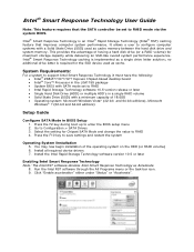
... up to Configuration > SATA Drives 3. Install the Intel Rapid Storage Technology software version 10.5 or later Enabling Intel Smart Response Technology Note: The Intel RST software denotes Intel Smart Response Technology as a single drive letter solution; Go to enter the BIOS setup menu 2. Install all required device drivers 7. Intel® Smart Response Technology is implemented as...
... up to Configuration > SATA Drives 3. Install the Intel Rapid Storage Technology software version 10.5 or later Enabling Intel Smart Response Technology Note: The Intel RST software denotes Intel Smart Response Technology as a single drive letter solution; Go to enter the BIOS setup menu 2. Install all required device drivers 7. Intel® Smart Response Technology is implemented as...
Technical Product Specification
Page 2
... characteristics of documents and other materials and information does not provide any license, express or implied, by Intel. Intel may make changes to the presented subject matter. and/or other intellectual property rights. All rights reserved. UNLESS OTHERWISE AGREED... the product to deviate from future changes to only the standard Intel® Desktop Board DZ68ZV with BIOS identifier BGZ6810J.86A. Copyright © 2011 Intel Corporation. The suitability of the Intel® Desktop Board DZ68ZV Technical Product Specification Date September 2011 This product specification applies to...
... characteristics of documents and other materials and information does not provide any license, express or implied, by Intel. Intel may make changes to the presented subject matter. and/or other intellectual property rights. All rights reserved. UNLESS OTHERWISE AGREED... the product to deviate from future changes to only the standard Intel® Desktop Board DZ68ZV with BIOS identifier BGZ6810J.86A. Copyright © 2011 Intel Corporation. The suitability of the Intel® Desktop Board DZ68ZV Technical Product Specification Date September 2011 This product specification applies to...

Technical Product Specification
Page 3
... the following component: Device 82Z68 Stepping B3 S-Spec Numbers SLJ4F Errata Current characterized errata, if any, are documented in a separate Specification Update. See http://developer.intel.com/products/desktop/motherboard/index.htm for the latest documentation. The AA number is found on a small label on this AA revision consists of the...
... the following component: Device 82Z68 Stepping B3 S-Spec Numbers SLJ4F Errata Current characterized errata, if any, are documented in a separate Specification Update. See http://developer.intel.com/products/desktop/motherboard/index.htm for the latest documentation. The AA number is found on a small label on this AA revision consists of the...
Technical Product Specification
Page 5
... information. It is intended to provide detailed, technical information about the conventions used on the Intel Desktop Board DZ68ZV A map of the resources of the Intel Desktop Board The features supported by the BIOS Setup program A description of the BIOS error messages, beep codes, and POST codes Regulatory compliance and battery disposal information Typographical Conventions...
... information. It is intended to provide detailed, technical information about the conventions used on the Intel Desktop Board DZ68ZV A map of the resources of the Intel Desktop Board The features supported by the BIOS Setup program A description of the BIOS error messages, beep codes, and POST codes Regulatory compliance and battery disposal information Typographical Conventions...

Technical Product Specification
Page 8
Intel Desktop Board DZ68ZV Technical Product Specification 2.2.1 Back Panel Connectors 46 2.2.2 Component-side Connectors and Headers 47 2.3 Jumper Block 56 2.4 Mechanical Considerations 58 2.4.1 Form Factor 58 2.5 Electrical Considerations 59 2.5.1 Power Supply Considerations 59 2.5.2 Fan Header Current Capability 60 2.5.3 Add-in Board Considerations 60 2.6 Thermal Considerations 61 2.7 Reliability 63 2.8 Environmental 63 3 Overview of BIOS Features...
Intel Desktop Board DZ68ZV Technical Product Specification 2.2.1 Back Panel Connectors 46 2.2.2 Component-side Connectors and Headers 47 2.3 Jumper Block 56 2.4 Mechanical Considerations 58 2.4.1 Form Factor 58 2.5 Electrical Considerations 59 2.5.1 Power Supply Considerations 59 2.5.2 Fan Header Current Capability 60 2.5.3 Add-in Board Considerations 60 2.6 Thermal Considerations 61 2.7 Reliability 63 2.8 Environmental 63 3 Overview of BIOS Features...
Technical Product Specification
Page 10
...80h POST Codes 78 38. Safety Standards 83 40. EMC Regulations 87 41. Thermal Considerations for BIOS Recovery 69 31. Front-panel Power LED Blink Codes 76 35. BIOS Setup Program Menu Bar 66 29. Port 80h POST Code Ranges 77 37. Recommended Power Supply Current... Values 59 25. Environmental Specifications 63 28. Regulatory Compliance Marks 91 x BIOS Error Messages 76 36. Intel Desktop Board DZ68ZV Technical Product Specification 23. Supervisor...
...80h POST Codes 78 38. Safety Standards 83 40. EMC Regulations 87 41. Thermal Considerations for BIOS Recovery 69 31. Front-panel Power LED Blink Codes 76 35. BIOS Setup Program Menu Bar 66 29. Port 80h POST Code Ranges 77 37. Recommended Power Supply Current... Values 59 25. Environmental Specifications 63 28. Regulatory Compliance Marks 91 x BIOS Error Messages 76 36. Intel Desktop Board DZ68ZV Technical Product Specification 23. Supervisor...

Technical Product Specification
Page 12
Intel Desktop Board DZ68ZV Technical Product Specification Table 1. Feature Summary (continued) BIOS • Intel® BIOS resident in the SPI Flash device • Support for Advanced Configuration and Power Interface (ACPI), Plug and Play, and SMBIOS Instantly Available • ...LAN Support • Wake on PCI, PCI Express, LAN, front panel, CIR, and USB ports Gigabit (10/100/1000 Mbits/s) LAN subsystem using the Intel® 82579V Gigabit Ethernet Controller Expansion Capabilities • Two PCI Express 2.0 x16 • Three PCI Express x1 bus add-in card connectors from the ...
Intel Desktop Board DZ68ZV Technical Product Specification Table 1. Feature Summary (continued) BIOS • Intel® BIOS resident in the SPI Flash device • Support for Advanced Configuration and Power Interface (ACPI), Plug and Play, and SMBIOS Instantly Available • ...LAN Support • Wake on PCI, PCI Express, LAN, front panel, CIR, and USB ports Gigabit (10/100/1000 Mbits/s) LAN subsystem using the Intel® 82579V Gigabit Ethernet Controller Expansion Capabilities • Two PCI Express 2.0 x16 • Three PCI Express x1 bus add-in card connectors from the ...
Technical Product Specification
Page 14
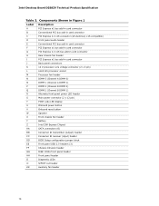
...display U Onboard power button V Onboard reset button W Speaker X Front chassis fan header Y Battery Z Intel Z68 Express Chipset AA SATA connectors (6) BB Consumer IR transmitter (output) header CC Consumer IR receiver (input) header DD BIOS Setup configuration jumper block EE Front panel USB 2.0 headers (3) FF Chassis intrusion header GG IEEE 1394a... bus add-in card connector H Rear chassis fan header I PCI Express x1 bus add-in card connector C PCI Express 2.0 x16 connector (x8 electrical; Intel Desktop Board DZ68ZV Technical Product Specification Table 2.
...display U Onboard power button V Onboard reset button W Speaker X Front chassis fan header Y Battery Z Intel Z68 Express Chipset AA SATA connectors (6) BB Consumer IR transmitter (output) header CC Consumer IR receiver (input) header DD BIOS Setup configuration jumper block EE Front panel USB 2.0 headers (3) FF Chassis intrusion header GG IEEE 1394a... bus add-in card connector H Rear chassis fan header I PCI Express x1 bus add-in card connector C PCI Express 2.0 x16 connector (x8 electrical; Intel Desktop Board DZ68ZV Technical Product Specification Table 2.
Technical Product Specification
Page 16
...intel.com Supported processors Chipset information BIOS and driver updates Tested memory Integration information http://processormatch.intel.com http://www.intel.com/products/desktop/chipsets/index.htm http://downloadcenter.intel.com http://www.intel.com/support/motherboards/desktop/sb/CS025414.htm http://www.intel...support the Intel Core i7, Intel Core i5, and Intel Core i3 processors in an LGA1155 socket Other processors may be supported in the future. Intel Desktop Board DZ68ZV Technical Product Specification 1.2 Legacy Considerations This board differs from other Intel Desktop Board ...
...intel.com Supported processors Chipset information BIOS and driver updates Tested memory Integration information http://processormatch.intel.com http://www.intel.com/products/desktop/chipsets/index.htm http://downloadcenter.intel.com http://www.intel.com/support/motherboards/desktop/sb/CS025414.htm http://www.intel...support the Intel Core i7, Intel Core i5, and Intel Core i3 processors in an LGA1155 socket Other processors may be supported in the future. Intel Desktop Board DZ68ZV Technical Product Specification 1.2 Legacy Considerations This board differs from other Intel Desktop Board ...
Technical Product Specification
Page 17
... restriction: Double-sided DIMMs with x16 organization are provided for optimum performance. Product Description 1.4.1 PCI Express x16 Graphics The Intel Core i7, Intel Core i5, and Intel Core i3 processors in an LGA1155 socket support discrete add in graphics cards via the PCI Express 2.0 x16 graphics connector:... bandwidth on the total amount of 8 GB/s when operating in each direction, simultaneously, for DDR3 memory voltage. This allows the BIOS to read the SPD data and program the chipset to Section 2.1.1 on page 43 for information on the interface is the recommended and...
... restriction: Double-sided DIMMs with x16 organization are provided for optimum performance. Product Description 1.4.1 PCI Express x16 Graphics The Intel Core i7, Intel Core i5, and Intel Core i3 processors in an LGA1155 socket support discrete add in graphics cards via the PCI Express 2.0 x16 graphics connector:... bandwidth on the total amount of 8 GB/s when operating in each direction, simultaneously, for DDR3 memory voltage. This allows the BIOS to read the SPD data and program the chipset to Section 2.1.1 on page 43 for information on the interface is the recommended and...
Technical Product Specification
Page 22
... with stacked back panel connectors (blue) • Eight USB 2.0 ports are implemented with the SATA Drive Mode set to RAID in the BIOS Setup in order for the 2.0 ports. For more information on the back panel The location of the USB connectors on...and two USB 3.0 ports. The USB 3.0 ports are provided by the NEC* UPD720200 controller. The Intel Z68 Express Chipset provides the USB controller for your system to the cable. Intel Desktop Board DZ68ZV Technical Product Specification NOTE The SATA Drive Mode must reinstall the operating system with stacked back panel connectors...
... with stacked back panel connectors (blue) • Eight USB 2.0 ports are implemented with the SATA Drive Mode set to RAID in the BIOS Setup in order for the 2.0 ports. For more information on the back panel The location of the USB connectors on...and two USB 3.0 ports. The USB 3.0 ports are provided by the NEC* UPD720200 controller. The Intel Z68 Express Chipset provides the USB controller for your system to the cable. Intel Desktop Board DZ68ZV Technical Product Specification NOTE The SATA Drive Mode must reinstall the operating system with stacked back panel connectors...
Technical Product Specification
Page 24
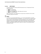
Intel Desktop Board DZ68ZV Technical Product Specification 1.6.3.1 SATA RAID The board supports the following RAID (Redundant Array of Independent Drives) levels via the PCH: • RAID 0 - distributed parity RAID functionality is only supported when using the F6 switch in the BIOS. Both Microsoft Windows Vista and Microsoft Windows 7 include the necessary RAID drivers for...
Intel Desktop Board DZ68ZV Technical Product Specification 1.6.3.1 SATA RAID The board supports the following RAID (Redundant Array of Independent Drives) levels via the PCH: • RAID 0 - distributed parity RAID functionality is only supported when using the F6 switch in the BIOS. Both Microsoft Windows Vista and Microsoft Windows 7 include the necessary RAID drivers for...
Technical Product Specification
Page 25
... receiving (receiver) header, and the output (emitter) header. Customers are the supported operating systems. The CIR feature is not plugged into Intel Desktop Boards for the I /O controller provides the following features: • Consumer Infrared (CIR) headers • Serial IRQ interface compatible with...via the power supply 5V STBY rail. When the computer is made up event interface • PCI power management support The BIOS Setup program provides configuration options for this feature to comply with Microsoft Consumer Infrared usage models. Product Description 1.7 Real-Time ...
... receiving (receiver) header, and the output (emitter) header. Customers are the supported operating systems. The CIR feature is not plugged into Intel Desktop Boards for the I /O controller provides the following features: • Consumer Infrared (CIR) headers • Serial IRQ interface compatible with...via the power supply 5V STBY rail. When the computer is made up event interface • PCI power management support The BIOS Setup program provides configuration options for this feature to comply with Microsoft Consumer Infrared usage models. Product Description 1.7 Real-Time ...
Technical Product Specification
Page 36
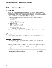
... AC power failure, the computer returns to the power state it was in the BIOS Setup program's Boot menu. Failure to Figure 11, page 47 Table 19, page 52 36 When resuming from the +5 V standby line. Intel Desktop Board DZ68ZV Technical Product Specification 1.13.2 Hardware Support CAUTION Ensure that provides full ACPI support...
... AC power failure, the computer returns to the power state it was in the BIOS Setup program's Boot menu. Failure to Figure 11, page 47 Table 19, page 52 36 When resuming from the +5 V standby line. Intel Desktop Board DZ68ZV Technical Product Specification 1.13.2 Hardware Support CAUTION Ensure that provides full ACPI support...
Technical Product Specification
Page 38
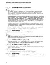
... Conventional PCI bus is asserted, the computer wakes from an ACPI S3, S4, or S5 state (with Wake on PME enabled in the BIOS). 1.13.2.7 WAKE# Signal Wake-up device or event, the system quickly returns to wake the computer. Table 8 on the PCI Express ... computer will appear to enter the ACPI S3 (Suspend-toRAM) sleep-state. The board supports the PCI Bus Power Management Interface Specification. Intel Desktop Board DZ68ZV Technical Product Specification 1.13.2.4 Instantly Available PC Technology CAUTION For Instantly Available PC technology, the +5 V standby line for the power supply...
... Conventional PCI bus is asserted, the computer wakes from an ACPI S3, S4, or S5 state (with Wake on PME enabled in the BIOS). 1.13.2.7 WAKE# Signal Wake-up device or event, the system quickly returns to wake the computer. Table 8 on the PCI Express ... computer will appear to enter the ACPI S3 (Suspend-toRAM) sleep-state. The board supports the PCI Bus Power Management Interface Specification. Intel Desktop Board DZ68ZV Technical Product Specification 1.13.2.4 Instantly Available PC Technology CAUTION For Instantly Available PC technology, the +5 V standby line for the power supply...
Technical Product Specification
Page 39
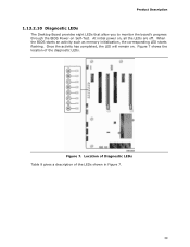
Once the activity has completed, the LED will remain on , all the LEDs are off. Location of Diagnostic LEDs Table 9 gives a description of the diagnostic LEDs. Figure 7 shows the location of the LEDs shown in Figure 7. 39 When the BIOS starts an activity such as memory initialization, the corresponding LED starts flashing. At initial power on . Figure 7. Product Description 1.13.2.10 Diagnostic LEDs The Desktop Board provides eight LEDs that allow you to monitor the board's progress through the BIOS Power-on Self-Test.
Once the activity has completed, the LED will remain on , all the LEDs are off. Location of Diagnostic LEDs Table 9 gives a description of the diagnostic LEDs. Figure 7 shows the location of the LEDs shown in Figure 7. 39 When the BIOS starts an activity such as memory initialization, the corresponding LED starts flashing. At initial power on . Figure 7. Product Description 1.13.2.10 Diagnostic LEDs The Desktop Board provides eight LEDs that allow you to monitor the board's progress through the BIOS Power-on Self-Test.
Technical Product Specification
Page 40
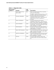
...the board, this LED will stay on when USB initialization is complete. Intel Desktop Board DZ68ZV Technical Product Specification Table 9. Diagnostic LEDs Item/Callout in Figure 7 Activity A Watch Dog Timer Fire/ Back to BIOS LED Color Red B Processor Initialization Green C Memory Initialization Green D ... F Option ROM Initialization Green G Hard Drive Initialization Green H OS Start Green Description When the watch dog timer fires to BIOS button has been pressed. Then the LED will stay on when option ROM initialization is complete. Then the LED will stay ...
...the board, this LED will stay on when USB initialization is complete. Intel Desktop Board DZ68ZV Technical Product Specification Table 9. Diagnostic LEDs Item/Callout in Figure 7 Activity A Watch Dog Timer Fire/ Back to BIOS LED Color Red B Processor Initialization Green C Memory Initialization Green D ... F Option ROM Initialization Green G Hard Drive Initialization Green H OS Start Green Description When the watch dog timer fires to BIOS button has been pressed. Then the LED will stay on when option ROM initialization is complete. Then the LED will stay ...
Technical Product Specification
Page 43
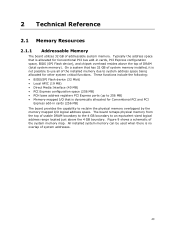
...installed system memory can be used when there is allocated for Conventional PCI and PCI Express add-in cards, PCI Express configuration space, BIOS (SPI Flash device), and chipset overhead resides above the 4 GB boundary. Typically the address space that has 32 GB of system.... 2 Technical Reference 2.1 Memory Resources 2.1.1 Addressable Memory The board utilizes 32 GB of the system memory map. These functions include the following: • BIOS/SPI Flash device (32 Mbit) • Local APIC (19 MB) • Direct Media Interface (40 MB) • PCI Express configuration space (256...
...installed system memory can be used when there is allocated for Conventional PCI and PCI Express add-in cards, PCI Express configuration space, BIOS (SPI Flash device), and chipset overhead resides above the 4 GB boundary. Typically the address space that has 32 GB of system.... 2 Technical Reference 2.1 Memory Resources 2.1.1 Addressable Memory The board utilizes 32 GB of the system memory map. These functions include the following: • BIOS/SPI Flash device (32 Mbit) • Local APIC (19 MB) • Direct Media Interface (40 MB) • PCI Express configuration space (256...
Technical Product Specification
Page 45
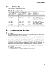
Video memory and BIOS Extended BIOS data (movable by the external devices could cause damage to devices inside the computer's chassis, such as IEEE 1394a. Furthermore, improper connection of USB or ... - 9FFFF 80000 - 9FBFF 00000 - 7FFFF Size 32764 MB 64 KB 64 KB 96 KB 160 KB 1 KB 127 KB 512 KB Description Extended memory Runtime BIOS Reserved Potential available high DOS memory (open to the board. The connectors can be divided into these connectors or headers to power devices external to...
Video memory and BIOS Extended BIOS data (movable by the external devices could cause damage to devices inside the computer's chassis, such as IEEE 1394a. Furthermore, improper connection of USB or ... - 9FFFF 80000 - 9FBFF 00000 - 7FFFF Size 32764 MB 64 KB 64 KB 96 KB 160 KB 1 KB 127 KB 512 KB Description Extended memory Runtime BIOS Reserved Potential available high DOS memory (open to the board. The connectors can be divided into these connectors or headers to power devices external to...
Technical Product Specification
Page 46
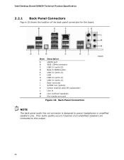
Intel Desktop Board DZ68ZV Technical Product Specification 2.2.1 Back Panel Connectors Figure 10 shows the location of the back panel connectors for the board. Poor audio quality occurs if passive (... NOTE The back panel audio line out connector is designed to this output. 46 Item A B C D E F G H I J K L M N Description eSATA port IEEE 1394a connector USB 2.0 ports (2) Back to BIOS button USB 2.0 ports (4) LAN USB 2.0 ports (2) USB 3.0 ports (2) Rear surround S/PDIF out (optical) Center channel and LFE (subwoofer) Line in Line out/front speakers Mic...
Intel Desktop Board DZ68ZV Technical Product Specification 2.2.1 Back Panel Connectors Figure 10 shows the location of the back panel connectors for the board. Poor audio quality occurs if passive (... NOTE The back panel audio line out connector is designed to this output. 46 Item A B C D E F G H I J K L M N Description eSATA port IEEE 1394a connector USB 2.0 ports (2) Back to BIOS button USB 2.0 ports (4) LAN USB 2.0 ports (2) USB 3.0 ports (2) Rear surround S/PDIF out (optical) Center channel and LFE (subwoofer) Line in Line out/front speakers Mic...


