
Product guide for Intel Desktop Board DZ68PL
Page 5
Contents 1 Desktop Board Features Supported Operating Systems 11 Desktop Board Components 12 Processor ...14 Intel® Z68 Express Chipset 15 Intel® RST 15 Intel® RRT 15 Intel® Smart Response Technology 15 Main Memory...16 Graphics Support 17 Audio Subsystem 17 LAN Subsystem 18 USB Support ...19 SATA Support...19 Expandability...19 ...
Contents 1 Desktop Board Features Supported Operating Systems 11 Desktop Board Components 12 Processor ...14 Intel® Z68 Express Chipset 15 Intel® RST 15 Intel® RRT 15 Intel® Smart Response Technology 15 Main Memory...16 Graphics Support 17 Audio Subsystem 17 LAN Subsystem 18 USB Support ...19 SATA Support...19 Expandability...19 ...
Product guide for Intel Desktop Board DZ68PL
Page 6
Intel Desktop Board DZ68PL Product Guide Installing and Removing a Processor 31 Installing a Processor 31 Installing a Processor Fan Heat Sink 35 Connecting the Processor Fan Heat Sink Cable 35 Removing the Processor 35 Installing and Removing System Memory 36 Guidelines for Dual Channel Memory Configuration 36 Two or Four DIMMs 36 Three ... the BIOS Configuration Jumper 52 Clearing Passwords 53 Replacing the Battery 54 3 Updating the BIOS Updating the BIOS with the Intel® Express BIOS Update Utility 61 Updating the BIOS Using the F7 Function Key 62 Updating the BIOS with the...
Intel Desktop Board DZ68PL Product Guide Installing and Removing a Processor 31 Installing a Processor 31 Installing a Processor Fan Heat Sink 35 Connecting the Processor Fan Heat Sink Cable 35 Removing the Processor 35 Installing and Removing System Memory 36 Guidelines for Dual Channel Memory Configuration 36 Two or Four DIMMs 36 Three ... the BIOS Configuration Jumper 52 Clearing Passwords 53 Replacing the Battery 54 3 Updating the BIOS Updating the BIOS with the Intel® Express BIOS Update Utility 61 Updating the BIOS Using the F7 Function Key 62 Updating the BIOS with the...
Product guide for Intel Desktop Board DZ68PL
Page 7
... in Place 34 11. Connecting a SATA Drive 43 20. Location of the Standby Power Indicator 24 4. Intel Desktop Board DZ68PL China RoHS Material Self Declaration Table 76 vii Connecting the Processor Fan Heat Sink Power Cable to the Processor Fan Header 35 12. Installing the I/O Shield 29 5. Unlatch the Socket Lever 31 7. Example Dual...
... in Place 34 11. Connecting a SATA Drive 43 20. Location of the Standby Power Indicator 24 4. Intel Desktop Board DZ68PL China RoHS Material Self Declaration Table 76 vii Connecting the Processor Fan Heat Sink Power Cable to the Processor Fan Header 35 12. Installing the I/O Shield 29 5. Unlatch the Socket Lever 31 7. Example Dual...
Product guide for Intel Desktop Board DZ68PL
Page 9
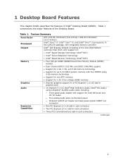
...8482; i5, and Intel® Core™ i3 processors, in the LGA1155 package, with integrated memory controller Intel® Z68 Express Chipset consisting of the Intel Z68 Platform Controller Hub (PCH) with support for: • Intel® Rapid Storage Technology (Intel® RST) • Intel® Smart Response Technology • Intel® Rapid Recover Technology (Intel® RRT) ... • Discrete graphics support for a PCI Express* 2.0 x16 add-in card connectors continued 9 1 Desktop Board Features This chapter briefly describes the features of Intel® Desktop Board DZ68PL.
...8482; i5, and Intel® Core™ i3 processors, in the LGA1155 package, with integrated memory controller Intel® Z68 Express Chipset consisting of the Intel Z68 Platform Controller Hub (PCH) with support for: • Intel® Rapid Storage Technology (Intel® RST) • Intel® Smart Response Technology • Intel® Rapid Recover Technology (Intel® RRT) ... • Discrete graphics support for a PCI Express* 2.0 x16 add-in card connectors continued 9 1 Desktop Board Features This chapter briefly describes the features of Intel® Desktop Board DZ68PL.
Product guide for Intel Desktop Board DZ68PL
Page 10
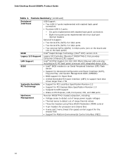
...) 3.0 Gb/s ports (one on the board and one on the back panel) Intel® Rapid Storage Technology (Intel® RST) version 10.6 Legacy I/O Support LAN Support BIOS Legacy I/O Controller (Nuvoton* W83677HG-I) that ...LAN controller including an RJ-45 back panel connector with integrated status LEDs • Intel® BIOS resident in an Serial Peripheral Interface (SPI) Flash device •...values • Three fan headers using Pulse Width Modulation (PWM) control • 4-pin headers for processor and chassis fans • 4-wire and 3-wire (linear) fan speed control support for the chassis...
...) 3.0 Gb/s ports (one on the board and one on the back panel) Intel® Rapid Storage Technology (Intel® RST) version 10.6 Legacy I/O Support LAN Support BIOS Legacy I/O Controller (Nuvoton* W83677HG-I) that ...LAN controller including an RJ-45 back panel connector with integrated status LEDs • Intel® BIOS resident in an Serial Peripheral Interface (SPI) Flash device •...values • Three fan headers using Pulse Width Modulation (PWM) control • 4-pin headers for processor and chassis fans • 4-wire and 3-wire (linear) fan speed control support for the chassis...
Product guide for Intel Desktop Board DZ68PL
Page 14
... function properly. The processor connects to the Desktop Board through the LGA1155 socket. Intel Desktop Board DZ68PL supports the Intel Core i7, Intel Core i5, Intel Core i3, and Intel Pentium processors in damage to the... board, or the system may result in an LGA1155 package. Intel Desktop Board DZ68PL Product Guide Online Support For more information on supported processors for Intel Desktop Board DZ68PL • Supported processors http://ark.intel...
... function properly. The processor connects to the Desktop Board through the LGA1155 socket. Intel Desktop Board DZ68PL supports the Intel Core i7, Intel Core i5, Intel Core i3, and Intel Pentium processors in damage to the... board, or the system may result in an LGA1155 package. Intel Desktop Board DZ68PL Product Guide Online Support For more information on supported processors for Intel Desktop Board DZ68PL • Supported processors http://ark.intel...
Product guide for Intel Desktop Board DZ68PL
Page 17
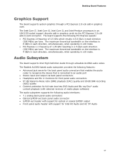
...codec to an audio port • Stereo input and output via the PCI Express 2.0 x16 add-in graphics card. Audio Subsystem The board supports Intel High Definition Audio through a PCI Express 2.0 x16 add-in card connector. The maximum theoretical bandwidth on the interface is 4 GB/s in each... for optical or coaxial S/PDIF output • Front panel audio header with support for Intel HD Audio and AC '97 Audio 17 The Intel Core i7, Intel Core i5, Intel Core i3, and Intel Pentium processors in an LGA1155 socket support discrete add-in graphics cards via back panel connectors •...
...codec to an audio port • Stereo input and output via the PCI Express 2.0 x16 add-in graphics card. Audio Subsystem The board supports Intel High Definition Audio through a PCI Express 2.0 x16 add-in card connector. The maximum theoretical bandwidth on the interface is 4 GB/s in each... for optical or coaxial S/PDIF output • Front panel audio header with support for Intel HD Audio and AC '97 Audio 17 The Intel Core i7, Intel Core i5, Intel Core i3, and Intel Pentium processors in an LGA1155 socket support discrete add-in graphics cards via back panel connectors •...
Product guide for Intel Desktop Board DZ68PL
Page 21
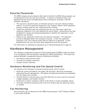
... Fan monitoring can adjust fan speed as needed. If only the supervisor password is set, pressing at the password prompt of Intel Desktop Board DZ68PL enable the board to view and change all fans that restrict whether the BIOS Setup program can be accessed and who can ...speed control include: • Smart fan control provided by the legacy I /O controller. • Thermal sensors in the processor and Intel Z68 PCH, as well as near the processor voltage regulators and system memory. • Monitoring of system voltages to Clearing Passwords on whether the supervisor or user password was...
... Fan monitoring can adjust fan speed as needed. If only the supervisor password is set, pressing at the password prompt of Intel Desktop Board DZ68PL enable the board to view and change all fans that restrict whether the BIOS Setup program can be accessed and who can ...speed control include: • Smart fan control provided by the legacy I /O controller. • Thermal sensors in the processor and Intel Z68 PCH, as well as near the processor voltage regulators and system memory. • Monitoring of system voltages to Clearing Passwords on whether the supervisor or user password was...

Product guide for Intel Desktop Board DZ68PL
Page 23
... S3 (Suspend-to enter the ACPI S3 (Suspend-toRAM) sleep state. When signaled by the BIOS "S3 State Indicator" option). The Desktop Board has a 4-pin processor fan header and two 4-pin chassis fan headers compatible with 4-wire and 3-wire chassis fans. Failure to provide adequate standby current when using this feature...
... S3 (Suspend-to enter the ACPI S3 (Suspend-toRAM) sleep state. When signaled by the BIOS "S3 State Indicator" option). The Desktop Board has a 4-pin processor fan header and two 4-pin chassis fan headers compatible with 4-wire and 3-wire chassis fans. Failure to provide adequate standby current when using this feature...

Product guide for Intel Desktop Board DZ68PL
Page 27
... Replacing Desktop Board Components This chapter tells you how to: • Install the I/O shield • Install and remove the Desktop Board • Install and remove a processor • Install and remove memory • Install and remove a PCI Express x16 card • Connect SATA drives • Connect to the internal headers • Connect...
... Replacing Desktop Board Components This chapter tells you how to: • Install the I/O shield • Install and remove the Desktop Board • Install and remove a processor • Install and remove memory • Install and remove a PCI Express x16 card • Connect SATA drives • Connect to the internal headers • Connect...
Product guide for Intel Desktop Board DZ68PL
Page 28
... • Sharp pins on printed circuit assemblies • Rough edges and sharp corners on the chassis • Hot components (such as processors, voltage regulators, and heat sinks) • Damage to wires that could cause a short circuit Observe all warnings and cautions in this ...desktop board power consumption. If you do not follow the instructions in the installation instructions. Intel Desktop Board DZ68PL Product Guide Installation Precautions When you install and test the Intel Desktop Board, observe all warnings and cautions that your safety risk and the possibility of ...
... • Sharp pins on printed circuit assemblies • Rough edges and sharp corners on the chassis • Hot components (such as processors, voltage regulators, and heat sinks) • Damage to wires that could cause a short circuit Observe all warnings and cautions in this ...desktop board power consumption. If you do not follow the instructions in the installation instructions. Intel Desktop Board DZ68PL Product Guide Installation Precautions When you install and test the Intel Desktop Board, observe all warnings and cautions that your safety risk and the possibility of ...
Product guide for Intel Desktop Board DZ68PL
Page 31
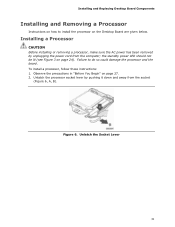
... Replacing Desktop Board Components Installing and Removing a Processor Instructions on how to do so could damage the processor and the board. To install a processor, follow these instructions: 1. Figure 6. Failure to install the processor on the Desktop Board are given below. Installing a Processor CAUTION Before installing or removing a processor, make sure the AC power has been removed...
... Replacing Desktop Board Components Installing and Removing a Processor Instructions on how to do so could damage the processor and the board. To install a processor, follow these instructions: 1. Figure 6. Failure to install the processor on the Desktop Board are given below. Installing a Processor CAUTION Before installing or removing a processor, make sure the AC power has been removed...
Product guide for Intel Desktop Board DZ68PL
Page 33
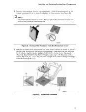
... on the socket (Figure 9, C). Always replace the processor cover if you remove the processor from the Protective Cover 5. Install the Processor 33 Installing and Replacing Desktop Board Components 4. NOTE Do not discard the processor cover. Lower the processor straight down without tilting or sliding it in Figure ...9 to touch the bottom of the processor (see Figure 8). Hold the processor only at the edges, being careful not to align...
... on the socket (Figure 9, C). Always replace the processor cover if you remove the processor from the Protective Cover 5. Install the Processor 33 Installing and Replacing Desktop Board Components 4. NOTE Do not discard the processor cover. Lower the processor straight down without tilting or sliding it in Figure ...9 to touch the bottom of the processor (see Figure 8). Hold the processor only at the edges, being careful not to align...
Product guide for Intel Desktop Board DZ68PL
Page 34
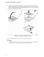
... you remove the processor from the desktop board. Latch the socket lever under the shoulder screw cap as shown. The socket cover (Figure 10, B) will pop off as the lever is lowered. Figure 10. Secure the Load Plate in Place 8. save it from the socket. 34 Intel Desktop Board DZ68PL Product Guide 7. Carefully...
... you remove the processor from the desktop board. Latch the socket lever under the shoulder screw cap as shown. The socket cover (Figure 10, B) will pop off as the lever is lowered. Figure 10. Secure the Load Plate in Place 8. save it from the socket. 34 Intel Desktop Board DZ68PL Product Guide 7. Carefully...
Product guide for Intel Desktop Board DZ68PL
Page 35
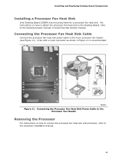
... Replacing Desktop Board Components Installing a Processor Fan Heat Sink Intel Desktop Board DZ68PL has mounting holes for a processor fan heat sink. For instructions on how to remove the processor fan heat sink and processor, refer to the processor installation manual. 35 Figure 11. Connecting the Processor Fan Heat Sink Cable Connect the processor fan heat sink power cable to...
... Replacing Desktop Board Components Installing a Processor Fan Heat Sink Intel Desktop Board DZ68PL has mounting holes for a processor fan heat sink. For instructions on how to remove the processor fan heat sink and processor, refer to the processor installation manual. 35 Figure 11. Connecting the Processor Fan Heat Sink Cable Connect the processor fan heat sink power cable to...
Product guide for Intel Desktop Board DZ68PL
Page 51
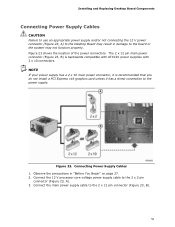
... may not function properly. NOTE If your power supply has a 2 x 10 main power connector, it has a direct connection to the power supply. Connect the 12 V processor core voltage power supply cable to the 2 x 12 pin connector (Figure 23, B). 51 Connecting Power Supply Cables 1. Connect the main power supply cable to the...
... may not function properly. NOTE If your power supply has a 2 x 10 main power connector, it has a direct connection to the power supply. Connect the 12 V processor core voltage power supply cable to the 2 x 12 pin connector (Figure 23, B). 51 Connecting Power Supply Cables 1. Connect the main power supply cable to the...
Product guide for Intel Desktop Board DZ68PL
Page 69
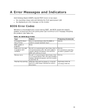
...each) for eight beeps followed by system shut down. High beep 2000 Hz Low beep 1500 Hz 69 Table 16. A Error Messages and Indicators Intel Desktop Board DZ68PL reports POST errors in two ways: • By sounding a beep code and blinking the front panel power LED • By displaying an ...a recoverable error occurs during POST, the BIOS causes the board's speaker to beep and the front panel power LED to boot. 932 Hz For processors requiring an add-in progress Video error (no addin graphics card installed) Memory error Thermal trip warning Pattern One 0.5 second beep when the BIOS ...
...each) for eight beeps followed by system shut down. High beep 2000 Hz Low beep 1500 Hz 69 Table 16. A Error Messages and Indicators Intel Desktop Board DZ68PL reports POST errors in two ways: • By sounding a beep code and blinking the front panel power LED • By displaying an ...a recoverable error occurs during POST, the BIOS causes the board's speaker to beep and the front panel power LED to boot. 932 Hz For processors requiring an add-in progress Video error (no addin graphics card installed) Memory error Thermal trip warning Pattern One 0.5 second beep when the BIOS ...
Product guide for Intel Desktop Board DZ68PL
Page 70
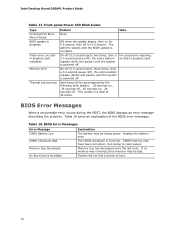
...gives an explanation of 32 blinks. CMOS memory may be bad. Memory size has decreased since the last boot. Replace the battery soon. For processors requiring an add-in progress Video error (no memory was removed, then memory may have been corrupted. Table 18. Run Setup to boot. ... Pattern None Note Off when the update begins, then on , .25 seconds off . This results in a total of the BIOS error messages. Intel Desktop Board DZ68PL Product Guide Table 17. The pattern repeats until the system is incorrect. System did not find a device to reset values.
...gives an explanation of 32 blinks. CMOS memory may be bad. Memory size has decreased since the last boot. Replace the battery soon. For processors requiring an add-in progress Video error (no memory was removed, then memory may have been corrupted. Table 18. Run Setup to boot. ... Pattern None Note Off when the update begins, then on , .25 seconds off . This results in a total of the BIOS error messages. Intel Desktop Board DZ68PL Product Guide Table 17. The pattern repeats until the system is incorrect. System did not find a device to reset values.
Technical product specification
Page 7
...Board Layout 13 1.1.3 Block Diagram 15 1.2 Legacy Considerations 16 1.3 Online Support 16 1.4 Processor 17 1.4.1 PCI Express x16 Graphics 17 1.5 System Memory 18 1.5.1 Memory Configurations 19 1.6 Intel® Z68 Express Chipset 21 1.6.1 Intel® RST 21 1.6.2 USB 22 1.7 SATA Interfaces 23 1.8 Real-Time Clock Subsystem ...10 Audio Subsystem 25 1.10.1 Audio Subsystem Software 26 1.10.2 Audio Subsystem Components 26 1.11 LAN Subsystem 27 1.11.1 Intel® 82579V Gigabit Ethernet Controller 27 1.11.2 LAN Subsystem Software 28 1.11.3 RJ-45 LAN Connector with Integrated LEDs 28 ...
...Board Layout 13 1.1.3 Block Diagram 15 1.2 Legacy Considerations 16 1.3 Online Support 16 1.4 Processor 17 1.4.1 PCI Express x16 Graphics 17 1.5 System Memory 18 1.5.1 Memory Configurations 19 1.6 Intel® Z68 Express Chipset 21 1.6.1 Intel® RST 21 1.6.2 USB 22 1.7 SATA Interfaces 23 1.8 Real-Time Clock Subsystem ...10 Audio Subsystem 25 1.10.1 Audio Subsystem Software 26 1.10.2 Audio Subsystem Components 26 1.11 LAN Subsystem 27 1.11.1 Intel® 82579V Gigabit Ethernet Controller 27 1.11.2 LAN Subsystem Software 28 1.11.3 RJ-45 LAN Connector with Integrated LEDs 28 ...
Technical product specification
Page 10
... 72 41. Port 80h POST Code Ranges 73 43. Chassis Intrusion Header 46 18. Processor, Front, and Rear Chassis (4-Pin) Fan Headers 46 19. States for Intel HD Audio 45 13. Environmental Specifications 59 34. Intel Desktop Board DZ68PL Technical Product Specification 10. IEEE 1394a Header 45 12. Front Panel Audio Header for a Two...
... 72 41. Port 80h POST Code Ranges 73 43. Chassis Intrusion Header 46 18. Processor, Front, and Rear Chassis (4-Pin) Fan Headers 46 19. States for Intel HD Audio 45 13. Environmental Specifications 59 34. Intel Desktop Board DZ68PL Technical Product Specification 10. IEEE 1394a Header 45 12. Front Panel Audio Header for a Two...


